

Page 1

imaging Series
4:2:2 Component
ASD-111i
Guide to Installation and Operation
M293-9900-201
Copyright 2002 Miranda Technologies Inc.
Specifications may be subject to change.
Printed in Canada
August 2002
Analog to Digital
Converter
1i
Miranda
Technologies inc.
3499 Douglas-B.-Floreani
St-Laurent, Québec, Canada H4S 1Y6
Tel. 514-333-1772
Fax. 514-333-9828
www.miranda.com
-11
ASD
Page 2

i
Page 3

WARRANTY POLICIES
Warranty Statement
Miranda Technologies Inc. warrants that the equipment it manufactures shall be free from defects in
material and workmanship for a period of two (2) years from the date of shipment from the factory. If
equipment fails due to such defects, Miranda Technologies Inc. will, at its option, repair or provide a
replacement for the defective part or product. Equipment that fails after the warranty period, has been
operated or installed in a manner other than that specified by Miranda, or has been subjected to abuse or
modification, will be repaired for time and material charges at the Buyer’s expense.
All out-of-warranty repairs are warranted for a period of ninety (90) days from the date of shipment from
the factory.
Miranda Technologies Inc. makes no other warranties, expressed or implied, of merchantability, fitness
for a particular purpose or otherwise. Miranda’s liability for any cause, including breach of contract,
breach of warranty, or negligence, with respect to products sold by it, is limited to repair or replacement
by Miranda, at its sole discretion. In no event shall Miranda Technologies Inc. be liable for any incidental
or consequential damages, including loss of profits.
Effective January 1, 2002
Warranty Exchange Policies
Miranda Technologies Inc. warrants that the equipment it manufactures shall be free from defects in
materials and workmanship for a period of two (2) years from the date of shipment from the factory. If
equipment fails due to such defects, Miranda will provide repair of the failed unit under the terms of the
Miranda warranty.
If the equipment has been proven to be defective on arrival, Miranda will ship a new product in exchange,
usually within 36 hours of factory notification.
If the equipment to be repaired is essential and the customer so requests, Miranda will, at its option,
provide a service replacement or loaner part or product, usually within 36 hours of factory notification,
weekends and holidays excluded.
All warranty exchange or loaner parts or products shall be shipped to the Buyer with a packing list clearly
describing the items and stating the date of shipment. Repaired parts or products will be shipped to the
Buyer with a similar packing list. In the case of exchange, the defective products or parts must be
returned to Miranda within fifteen (15) days from receipt by the customer of the exchange product. In the
case of a loaner, the loaned products or parts must be returned to Miranda within fifteen (15) days from
receipt by the customer of the repaired equipment.
If the equipment is not returned within fifteen (15) days, as described for either exchanges or loans, A
Rental Invoice will be generated. Rental terms will be fifteen (15) percent of the current list price of the
products or parts per month or a fraction thereof. Before returning the equipment to Miranda
Technologies Inc., for any reason, the Buyer must first obtain a Return Authorization Number from
Miranda Technologies Inc. Miranda Technologies Inc will pay freight and insurance charges for the
delivery of the loaner or exchange products or parts. Freight and insurance charges for the return of the
defective product or part will also be paid by Miranda Technologies.
Out-Of-Warranty Repair Policy
Miranda will repair equipment which is out of Warranty. The current pricing structure for this service is
available from the Miranda web site at
at (514) 333-1772. All out-of-warranty repairs are warranted for a period of 90 days from the date of
shipment from the factory. Before returning the equipment to Miranda Technologies Inc., for any reason,
the Buyer must first obtain a Return Authorization Number from Miranda Technologies Inc. In the case of
a product deemed by Miranda to be beyond repair, the customer must purchase a new product at current
retail prices.
The Buyer will pay freight and insurance charges for the return of the defective product or part to the
manufacturer for repair. Miranda Technologies will pay freight and insurance charges for the return of the
repaired product or part to the Buyer.
www.miranda.com
or from Miranda Technical Support Services
ii
Page 4

Out-Of Warranty Equipment Updates and Spare Parts Policy
Miranda Technologies’ current pricing structure for out-of-warranty equipment updates, or the sale of
spare parts, is available from Miranda Technical Support Services at (514) 333-1772.
ELECTROMAGNETIC COMPATIBILITY
- This equipment has been tested for verification of compliance with FCC Part 15,
Subpart B, class A requirements for Digital Devices.
- This equipment complies with the requirements of EN55022 Class A, Electromagnetic
Emissions, En 60555-2 & -3, Disturbance in Supply Systems and EN50082-1,
Electromagnetic Immunity.
How to contact us:
Head Office Miranda Europe Miranda Asia
Miranda Technologies Inc. 222, 226 Rue De Rosny Mita Nexus Bldg. 2F
3499 Douglas-B.-Floreani 93100 Montreuil 1-3-33 Mita, Minato-Ku
St. Laurent (Montreal), Que. H4S 1Y6 France Tokyo, Japan 108-0073
Canada
Tel +1 (514) 333-1772 +33 1 55 86 87 88 +81 3 5730 2988
Fax +1 (514) 333-6914 +33 1 55 86 00 29 +81 3 5730 2973
Toll free: 1-800-224-9828
www.miranda.com
iii
Page 5

Contents
1 ASD-111i 4:2:2 Analog to Digital Converter...........................................................
1
1.1 Introduction.......................................................................................................... 1
1.2 Features............................................................................................................... 1
2 Installation................................................................................................................ 3
2.1 ASD-111i Mechanical Installation........................................................................ 3
2.1.1 imaging Quartet, Quartet-C and Quartet-M Housing Frame......................
3
2.1.2 imaging Symphonie Housing Frame.......................................................... 3
2.1.2 imaging Solo Housing Frame.....................................................................
3
2.2 Rear Panel Label................................................................................................. 4
2.2.1 imaging Quartet/Quartet-C/Quartet-M/Solo Connector Label...................
4
2.2.2 imaging Symphonie Connector Label........................................................ 4
2.3 ASD-111i Electrical Installation............................................................................
5
3 Operation.................................................................................................................. 7
3.1 ASD-111i User Interface...................................................................................... 7
3.2 Line Format Status and Error Detection.............................................................. 8
3.3 Input Signal Format Selection..............................................................................
9
3.4 Automatic Calibration with Error Status............................................................... 9
3.5 Manual Calibration of Gain, Offset and Horizontal Centering..............................
10
3.6 Recalling Default Values......................................................................................
11
3.7 Vertical Ancillary Data Masking........................................................................... 12
3.8 Sync Selection..................................................................................................... 12
3.9 Coring Selection...................................................................................................
12
4 Specifications........................................................................................................... 13
5 Schematic Diagrams................................................................................................ 15
iv
Page 6

v
Page 7
1 ASD-111i 4:2:2 Analog to Digital Converter
1.1 Introduction
The ASD-111i is a high-quality 10-bit analog to digital 4:2:2 video converter. A wide
range of component analog video (CAV) inputs are supported including GBR,
SMPTE/EBU, Betacam, and MII. Its microcontroller-based technology simplifies
switching from one standard to another. As an EDH inserter, the ASD-111i will insert
EDH Check Sum and Flag information into the outgoing serial signal. The ASD-111i's
powerful automatic calibration feature can accommodate a non-standard video or
correct a calibration defect in the incoming video signal. Factory set with 11 different
formats, all user configurations are stored in non-volatile memory for ease of use.
The ASD-111i's digital oversampling offers the best signal quality, while digital
processing eliminates the need for analog adjustments. A total of three 4:2:2 serial
digital video outputs are supplied; all 4:2:2 outputs conform to the SMPTE 259M
standard.
The ASD-111i is a member of the imaging family of digital video cards and therefore
requires the imaging Quartet, Quartet-C or Quartet-M, imaging Solo or imaging
Symphonie housing frame for mounting and power.
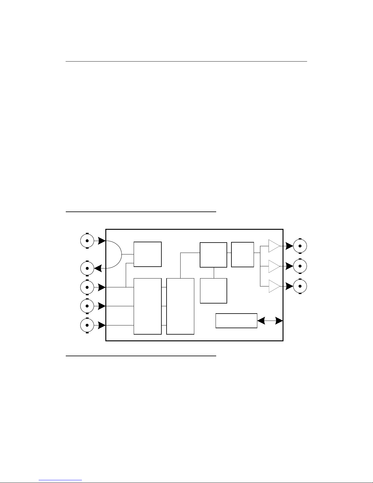
Figure 1.1 ASD-111i Functional Block Diagram
REF IN
G/Y
B/B-Y
R/R-Y
Genlock
Color
Space
Converter
ADC
Formatter
Calibration
Generator
1.2 Features
• GBR, SMPTE/EBU, Betacam
and MII analog inputs
• Automatic 525/625 input detection
• Studio reference input with loop-through
• Three 4:2:2 serial digital video outputs
• High-quality 10-bit signal path
• 2X oversampling
&
Test
Microcontroller
EDH
Insertion
REMOTE
CONTROL
1
4:2:2
2
OUT
3
1
Page 8

• Automatic input calibration
• Pre-calibration for 11 formats
• EDH Insertion (as per SMPTE-165M)
• Built-in color bars
• Black on loss of signal
• Horizontal centering adjustment
• External or sync-on-green sync selection
• Masking capability of incoming vertical ancillary data
• Coring function enabled with jumper setting
2
Page 9

2 Installation
2.1 ASD-111i Mechanical Installation
The ASD-111i must be mounted within Quartet, Quartet C, Quartet M,
Symphonie or Solo imaging housing frames in order to provide power to the
card. This section describes how to install the ASD-111i in any of these housing
frames. It is not necessary to switch off the power from these housing frames
when installing the SDM-111i.
2.1.1 imaging Quartet, Quartet C and Quartet M Housing Frames
To install this card into Quartet, Quartet C or Quartet M follow these steps. For a
closer look at card installation and removal, refer to the housing frame's Guide to
Installation and Operation.
1. Remove the housing frame's front panel by rotating the thumb screws
counter-clockwise. Pull on the handles.
2. Select an empty slot.
3. Carefully place the ASD-111i between a set of card guides and gently push
the card towards the rear of the housing frame until the card's edge
connector is secured to the backplane. Pull lightly on the card verifying that
it does not move.
4. Replace the housing frame's front panel. Make sure to rotate the thumb
screws clockwise in order to secure it to the chassis.
2.1.2 imaging Symphonie Housing Frame
To install this module into Symphonie follow these steps. For a closer look at
module installation and removal, refer to the frame's Guide to Installation and
Operation. You also need to install Symphonie-R-M or –R-C rear module for
complete installation.
1. Remove the front panel door by pulling on the door handles and gently
lowering it.
2. Select an empty compartment.
3. Carefully place the SDM-111i between the module guides and slowly push
the module towards the rear of the frame until the module's edge connector
is secured to its rear module. A light pressure to mate the connectors may
be required. Pull lightly on the module verifying that it does not move.
4. Replace the front panel door.
2.1.3 imaging Solo Housing Frame
To install this card into Solo follow these steps. For a closer look at card
installation and removal, refer to the housing frame's Guide to Installation and
Operation.
1. In order to remove the housing frame's front panel, gently pull on it.
3
Page 10

2. Carefully place the ASD-111i between the card guides and gently push the
card towards the rear of the housing frame until the card's edge connector is
secured to the backplane. Pull lightly on the card verifying that it does not
move.
3. Replace the housing frame's front panel.
2.2 Rear Panel Label
2.2.1 imaging Quartet/Quartet-C/Quartet-M/Solo Connector Label
A connector label has been shipped with your ASD-111i. This label is to be
installed on the housing frame's rear panel in order to identify the ASD-111i external
connectors. To install the label, follow these steps.
1. Remove the screws associated with the ASD-111i connectors.
2. Carefully apply the label to the connectors as shown in Figure 2.1.
3. Replace the screws making sure not to damage the label.
Figure 2.1 ASD-111i rear panel label installation
ASD-111i label
imaging Quartet
or
imaging Solo
(top view)
2.2.2 imaging Symphonie Connector Label
To install the Symphonie label, follow these steps while referring to Figure 2.2.
1. On Symphonie’s rear panel, locate the appropriate connectors.
2. Remove the rear label mounting screws from the rear module.
3. Carefully apply the label to the connectors making sure the label’s text is read
from top to bottom.
4
Page 11

4. Replace the screws making sure not to damage the label.
Figure 2.2 Symphonie rear panel label installation
REF IN
Label
ASD-111i COMPONENT ANALOG VIDEO TO 4:2:2 CONVERTER
G/Y
IN
B/B-Y R/R-Y
1 2 3
4:2:2 OUT
Rear module
2.3 ASD-111i Electrical Installation
When connecting the ASD-111i to external equipment, make sure that all serial
digital connections are point-to-point. For instance, there must be a point-to-point
connection between a 4:2:2 OUT BNC and target equipment. If a T-connector is
used to connect other equipment, the maximum specified cable length is no longer
valid.
5
Page 12

Also, make sure that the cable lengths of the output serial digital cables are a
maximum 250m (850') each. Refer to Figure 2.2 and to the following descriptions for
a complete ASD-111i electrical installation.
Studio reference input with loop-through output
For external synchronization, connect the studio reference signal to the BNC labeled
REF IN. To enable this input make sure the GBR SYNC jumper is in the REF
position. Refer to section 3, Operation.
When the REF IN BNC is in use, its loop-through output should be 75 ohm
terminated if it is not being used.
CAV inputs
Supported CAV input formats include GBR, SMPTE/EBU, Betacam, and MII. After
installing the CAV inputs make sure to program the ASD-111i for the appropriate
input format. Refer to section 3, Operation.
4:2:2 Serial digital video outputs
4:2:2 Serial digital component video signals are provided on the BNC connectors
labeled 4:2:2 OUT (1 to 3). These output signals conform to the SMPTE 259M
standard.
Figure 2.2 ASD-111i connections
ASD-111i COMPONENT ANALOG VIDEO TO 4:2:2 CONVERTER
REF IN
ASD-111i Back (Symphonie-R-C, Quartet and Quartet-C and Solo)
ASD-111i COMPONENT ANALOG VIDEO TO 4:2:2 CONVERTER
G/Y B/B-Y R/R-Y
REF IN
G/Y B/B-Y R/R-Y
IN
IN 4:2:2 OUT
ASD-111i Back (Symphonie-R-M, Quartet-M)
1 2 3
4:2:2 OUT
1 2
3
6
Page 13

3 Operation
3.1 ASD-111i User Interface
Figure 3.1 outlines the ASD-111i's user interface situated at the front end of the card.
The interface components include, from left to right:
• Line format status and error detection.
• Input signal format selection.
• Automatic calibration with error status.
• Manual calibration of gain, offset, and horizontal centering.
Location of the ASD-111i's jumpers on the card are indicated by figure 3.2. The
jumpers are:
• Vertical ancillary data masking jumper.
• Sync selection jumper.
• Coring selection jumper.
For operating information on the above functions, refer to the rest of this section.
Figure 3.1 Front panel interface
525 625 ERR
green
yellow
red
FORMAT
INPUT
GBR
BETA
SETUP
MIISMPTE
ASD-111i COMPONENT ANALOG VIDEO TO 4:2:2 CONVERTER
CALIB
ERR
TEST
MANUAL CALIBRATION
7
SELECT
Y
Y
B-Y
R-Y
OFST
GAIN
GAIN
GAINHCENTER
Page 14

Figure 3.2 Jumpers location
ASD-111i COMPONENT ANALOG VIDEO TO 4:2:2 CONVERTER
H
3.2 Line Format Status and Error Detection
The following indicators provide information on the ASD-111i's line format status.
Refer to Figure 3.1 for the correct indicator location.
• 525
This LED lights up to indicate the ASD-111i has detected a CAV input with a 525
line format.
• 625
This LED lights up to indicate the ASD-111i has detected a CAV input with a 625
line format.
• ERR
This LED lights up to indicate that no sync is being detected. During this time,
the corresponding 525 or 625 line format LED indicates the last valid format. At
all times, make sure that all CAV input signals are firmly installed and that source
equipment is functional. Also, depending on your installation, make sure the
ASD-111i is properly configured for external or sync-on-green synchronization.
8
Page 15

3.3 Input Signal Format Selection
The ASD-111i must be informed on the type of CAV input installed. The choices of
CAV inputs, as they successively appear when scrolled through, is shown in Figure
3.3 below. In order to program the appropriate format, use the FORMAT push-button
to scroll through the choices of CAV inputs. In more detail, follow these steps.
1. The current CAV format programmed for the ASD-111i is indicated by the status
of its corresponding LED. The list of LEDs are GBR, SMPTE, BETA, MII and
SETUP. Press the FORMAT push-button to select the next available CAV
format. Use Figure 3.3 as a guide.
2. After each key press, a new CAV format with or without setup is selected. If, for
instance, the SMPTE/EBU format is selected and FORMAT is pressed, then the
BETA LED will turn on and the ASD-111i will be programmed to receive a
Betacam signal without setup. One more key-press will program the ASD-111i
for Betacam with setup. When a format with setup is chosen, the yellow SETUP
LED will turn on.
3. Whenever power is removed from the ASD-111i, the CAV format programmed
prior to the removal of power is recorded. This recorded CAV format is used
when the ASD-111i is re-powered.
Figure 3.3 CAV format selection
Æ
525:
625:
GBRÆGBR w. setupÆSMPTEÆBETAÆBETA w. setupÆMIIÆMII w. setup
Æ
GBRÆSMPTEÆBETAÆMII
3.4 Automatic Calibration with Error Status
The automatic calibration function adjusts the gain and offset levels of the input CAV
signals in order to conform the output 4:2:2 serial digital signal to the SMPTE 259M
standard.
The ASD-111i executes automatic calibration by searching distinct areas in the video
signal for proper sampling. For this reason, it is highly recommended that a 75%,
100%, or SMPTE color bars test pattern be installed whenever performing automatic
calibration. Follow these in order to execute automatic calibration.
1. Install a 75%, 100%, or SMPTE color bars test pattern in the required video
format. If these test patterns are not available, ensure that the input signal has
yellow, cyan, and black situated in the zones as indicated in Figure 3.3.
2. Use the FORMAT push-button to select the video format being processed.
9
Page 16

3. Depress the CALIB. push-button for more than 2 seconds in order to execute
automatic calibration. For several seconds, the ASD-111i will attempt to conform
the output 4:2:2 signal to the SMPTE 259M standard. During this time, the ERR
calibration LED will flicker. The flickering will stop automatically after a complete
and successful calibration. Both offset and gain levels for the current format are
automatically stored.
4. If a particular parameter of the signal could not be calibrated, it will be indicated
by the ERR LED and the manual calibration LEDs. For example, if automatic
calibration failed to properly adjust Y gain, then the Y GAIN LED will be lit. Press
any push-button in order to cancel automatic calibration. No offset or gain levels
for the current format are stored.
Figure 3.3 Input signal sampling zones required during automatic calibration
White Yellow Cyan Green Magenta Red Blue Black
Y gain and B-Y gain
sampling zone
R-Y gain sampling zone
Y OFST (in setup format)
sampling zone
Y OFST (in non-setup format), B-Y OFST, and R-Y OFST sampled during blanking
3.5 Manual Calibration of Gain, Offset and Horizontal Centering
The manual calibration interface consists of the SELECT, +,
Y GAIN, Y OFST, B-Y GAIN, R-Y GAIN, and H CENTER LEDs. The list of
adjustable parameters include G/Y offset, gain for G/Y, B/B-Y, and R/R-Y, and
horizontal centering. When a parameter is selected, its corresponding LED lights up.
After manual calibration is enabled, a 1 minute delay with no push-button selection
will automatically disable manual calibration. However, any changes made are
stored.
To manually calibrate the ASD-111i refer to the following steps.
- push-buttons and the
10
Page 17

1. Make sure the ASD-111i is programmed for the type of input CAV signal being
processed. Use the FORMAT push-button to make any modifications. Refer to
the note following this procedure.
2. Depress the SELECT push-button. The Y GAIN, B-Y GAIN and R-Y GAIN LEDs
light up. Using the +/- push-buttons, a grouped gain calibration can be
performed.
3. Depress the SELECT push-button. The Y GAIN, B-Y GAIN and R-Y GAIN LEDs
turns off and the Y GAIN LED lights up. The +/- push-buttons may now be used
to adjust the output G/Y gain.
5. Depress the SELECT push-button. The Y GAIN LED turns off and the Y OFST
LED lights up. The +/- push-buttons may now be used to adjust the output G/Y
offset.
6. Depress the SELECT push-button. The Y OFST LED turns off and the B-Y
GAIN LED lights up. The +/- push-buttons may now be used to adjust the output
B/B-Y gain.
5. Depress the SELECT push-button. The B-Y GAIN LED turns off and the R-Y
GAIN LED lights up. The +/- push-buttons may now be used to adjust the output
R/R-Y gain.
6. The next parameter to be adjusted is horizontal centering. Horizontal centering
is the timing difference between the active video and the horizontal sync.
Depress the SELECT push-button. The R-Y GAIN LED turns off and the H
CENTER LED lights up. Use the +/- push-buttons to adjust the horizontal
centering which has an adjustment range of -8 to +6 pixels by steps of
approximately 1 ns. Alternatively, depressing and holding the FORMAT pushbutton while using the +/- push-buttons allows to make steps of 1/2 pixel.
7. Depress the SELECT push-button once again in order to store the new changes
and to disable manual calibration.
Note: You cannot adjust the Y GAIN for a format with setup if you do not have a
75%, 100%, or SMPTE color bars input CAV signal. This is due to the
fact that during manual calibration of the Y GAIN an automatic black level
correction is performed and therefore requires a signal with the correct
sampling zones. Refer to Figure 3.3. However, this constraint is not
applied when a non-setup format is employed because the automatic Y
OFST correction samples in the blanking region.
3.6 Recalling Default Values
In order to recall default values of the current video format make sure you are out of
manual calibration mode. Then, simultaneously press the +/- push-buttons. This
action will erase any changes made to the parameters by the user and recall the
default factory-set parameters. However, this procedure does not recall the H
CENTER parameter.
11
Page 18

In order to recall the default value of the H CENTER, you must enable manual
calibration by depressing the SELECT push-button until the the H CENTER LED
lights up. Finally, depress the +/- push-buttons simultaneously. This action will
erase any changes made to the the H CENTER parameter by the user.
3.7 Vertical Ancillary Data Masking
Any vertical ancillary data found on the CAV input signal lines listed in Table 3.2 may
be masked by the V ANC jumper. Perform the following steps in order to mask
vertical ancillary data or to allow it to pass through the ASD-111i.
1. Locate the V ANC jumper situated on the left side of the ASD-111i (refer to figure
3.2 for location).
2. To buffer through any vertical ancillary data set the jumper in the ON position. To
mask vertical ancillary data set the jumper in the OFF position.
Table 3.2 Masked video lines for 525 and 625 line formats
Masked Lines
525 Line
format
625 Line
format
10 to 19 and 273 to
281
6 to 22 and 319 to
335
3.8 Sync Selection
The ASD-111i can be synchronized to external equipment using an external
reference signal or sync information on the G/Y CAV input. In order to select
between the two modes of synchronization, refer to the following steps.
1. Locate the SYNC jumper (LK1) situated at the top right corner of the module
(refer to figure 3.2 for location).
2. If you are planning to use the studio reference signal to synchronize the ASD111i, set the jumper in the REF position. Make sure the studio reference signal
is connected to the REF IN connector on the rear panel.
3. In order to synchronize the ASD-111i to the G/Y CAV input signal set the jumper
to the G position. Make sure the G/Y input signal contains sync information.
3.9 Coring Selection
Coring reassigns any digital data points situated about the blanking level of the B/B-Y
and R/R-Y inputs, which do not have exact blanking levels, to true blanking levels.
This prevents any unwanted color modulation throughout the video signal during
reconstruction of the 4:2:2 output into NTSC or PAL.
12
Page 19

1. Locate the CORING jumper (LK2) situated on the left side of the ASD-111i (refer
to figure 3.2 for location).
2. To enable the coring function set the jumper in the ON position. In order to
remove the coring effect, set the jumper in the OFF position.
4 Specifications
Input
Signal: G/Y, B/B-Y, R/R-Y: 0.7 Vp-p nominal or 1.0 Vp-p nominal
with sync
Return loss: > 35 dB up to 5.75 MHz
Ext. ref: SMPTE 170M/PAL ITU 624-4 or 2 Vp-p/4 Vp-p
composite sync with passive loop-through
Return loss: > 35 dB up to 5.75 MHz
Output
Signal (3): 4:2:2 SMPTE 259M-C (270 Mbps)
Return loss: > 15 dB up to 270 MHz
Jitter (wideband) < 0.2 UI
Processing Performance
Quantization: 10 bits
Sampling: 27 MHz (2X oversampling)
Frequency response: ±0.1 dB to 5.5 MHz and +0/-0.15 dB from 5.5 to 5.75 MHz
Noise (unweighted): < -61 dB to 5.75 MHz
Processing delay: 2.7 µs
Horizontal centering: -8 pixels/+6 pixels by steps of 1 ns
Processing delay: 3.3 µs
Test signal: 100% color bars
Power: 14 W
Operating temperature range: 0 ºC to 40 ºC
13
Page 20

14
Page 21

5 Schematic DIagrams
15
 Loading...