

Page 1

Page 2

ELECTROMAGNETIC COMPATIBILITY
- This equipment has been tested for verification of compliance with FCC Part 15, Subpart
B, class A requirements for Digital Devices.
- This equipment complies with the requirements of EN55022 Class A, Electromagnetic
Emissions, En 60555-2 & -3, Disturbance in Supply Systems and EN50082-1,
Electromagnetic Immunity.
CONTACT MIRANDA
For technical assistance, please contact the Miranda Technical support centre nearest
you:
Americas
Telephone:
+1-800-224-7882
e-mail:
techsupp@miranda
.com
Visit our web site at www.miranda.com
Asia
Telephone:
+81-3-5730-2987
e-mail:
asiatech@miranda
.com
Europe, Middle East,
Africa, UK
Telephone:
+44 (0) 1491
820222
e-mail:
eurotech@miranda
.com
France (only)
Telephone:
+33 (0) 1 55 86 87
88
e-mail:
francetech@miranda
.com
i
Page 3

CONTENTS
1 AMX-101i Analog Audio Multiplexer .....................................................1
1.1 Introduction ............................................................................................................. 1
1.2 Features.................................................................................................................. 1
2 Installation.............................................................................................2
2.1 Unpacking............................................................................................................... 2
2.2 AMX-101i Mechanical Installation........................................................................... 2
2.3 Rear Panel Label .................................................................................................... 3
2.4 AMX-101i Electrical Installation............................................................................... 5
2.5 600 Ω Internal Termination Jumper........................................................................ 6
3 Operation..............................................................................................7
3.1 AMX-101i User Interface......................................................................................... 7
3.2 Menu Introduction ................................................................................................... 8
3.3 Input Status Monitoring......................................................................................... 10
3.4 Audio Status Monitoring........................................................................................ 10
3.5 Audio Group Selection.......................................................................................... 11
3.6 Mute Selection ...................................................................................................... 11
3.7 Level Adjustments................................................................................................. 12
3.8 Groups Present Monitoring................................................................................... 12
3.9 Channel Swapping................................................................................................ 13
3.10 Audio Delay......................................................................................................... 13
3.11 Overwrite............................................................................................................. 14
3.12 Channel Status Bit Selections............................................................................. 14
3.13 Calibration........................................................................................................... 14
3.14 Factory Reset...................................................................................................... 15
3.15 Tone and Color Bar Generator Selection............................................................ 15
4 Specifications......................................................................................16
ii
Page 4

1 AMX-101i Analog Audio Multiplexer
1.1 Introduction
The AMX-101i is a high-quality, high-performance analog audio
multiplexer/embedder designed to insert two 20-bit sampled analog audio stereo
signals into a single SMPTE 259M-C serial digital video signal. The AMX-101i
has an on-board audio test tone signal and automatic 525/625 input detection
with full EDH monitoring.
The AMX-101i is a member of the imaging family of digital video modules and
therefore requires the imaging Quartet-A-75 or the imaging Symphonie frame with
Symphonie-R-A75 rear module for mounting and power.
1.2 Features
Input
§ Serial digital 4:2:2 input with active loop-through
§ 2 stereo/4 monaural analog audio inputs
§ Automatic 525/625 input detection
§ Input error detection and handling (EDH) monitoring
§ 250 m automatic cable equalization
Outputs
§ 3 serial 4:2:2 digital video outputs
§ EDH insertion on all serial 4:2:2 outputs
Processing
§ 20-bit high-quality analog to digital audio conversion
§ Digital de-emphasis filter
§ Channel status bit insertion
§ -7 to +24 dBu input level range
§ Right/left swap capability
§ Channel swap capabilities
§ Programmable audio delay (up to 10 frames)
§ Built-in audio test tone and color bar test signals
1
Page 5

2 Installation
2.1 Unpacking
Make sure the following items have been shipped with the AMX-101i. If any of
the following items are missing, contact your distributor or Miranda Technologies
Inc.
§ AMX-101i Analog Audio Multiplexer
§ AMX-101i rear panel labels (2)
§ This manual
2.2 AMX-101i Mechanical Installation
Due to its audio inputs, the AMX-101i must be mounted within Quartet-A-75 or or
Symphonie imaging frames using Symphonie-R-A75 or Symphonie-R-A110 rear
modules. This section describes how to install the AMX-101i in any of these
frames. It is not necessary to switch off the power from these frames when
installing or removing the AMX-101i.
2.2.1 Quartet-A-75 Frame
To install this module into the audio Quartet frames follow these steps. For a
closer look at module installation and removal, refer to the frame's Guide to
Installation and Operation.
1. Remove the frame's front panel by rotating the thumb screws counterclockwise. Pull on the handles.
2. Select an empty slot.
3. Carefully place the AMX-101i between a set of module guides and gently
push the module towards the rear of the frame until the module's edge
connector is secured to the backplane. Pull lightly on the module verifying
that it does not move.
4. Replace the frame's front panel. Make sure to rotate the thumb screws
clockwise in order to secure it to the chassis.
2.2.2 Symphonie Frame
To install this module into the Symphonie housing frame, follow these steps. To
function, the AMX-101i requires the Symphonie-R-A75 or –R-A110 rear module.
For a closer look at module installation and removal, refer to the frame's Guide to
Installation and Operation.
1. Remove the front panel door by pulling on the door handles and gently
lowering it.
2. Select an empty slot.
3. Carefully place the module between the module guides and slowly push the
module towards the rear of the frame until the module's edge connector is
secured to its rear module. A light pressure to mate the connectors may be
required. Pull lightly on the module verifying that it does not move.
4. Replace the front panel door.
2
Page 6
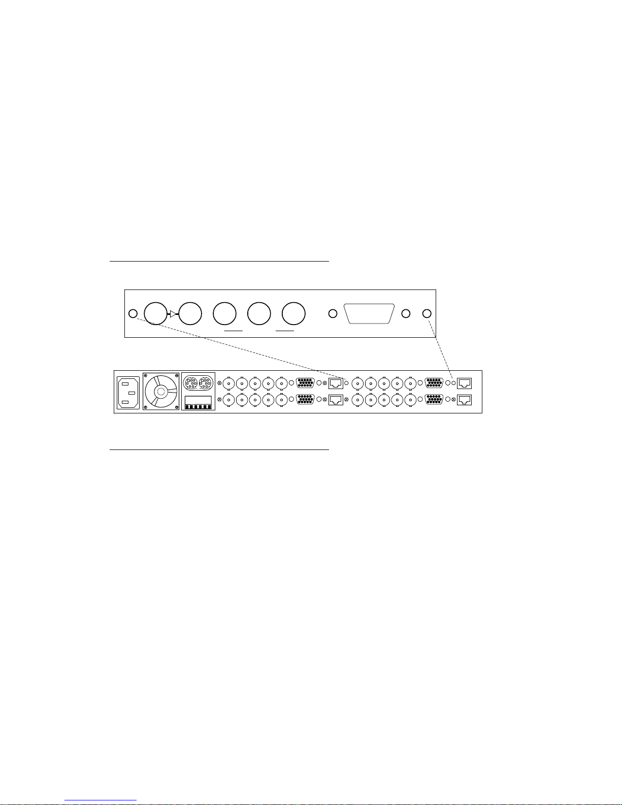
2.3 Rear Panel Label
A connector label has been shipped with the AMX-101i. This label is to be
installed on the frames’ rear panel in order to identify the module's external
connectors.
2.3.1 Quartet-A-75 Frame
To install the rear panel label on a Quartet-A-75 frame, follow these steps while
referring to Figure 2.1.
1. Remove the screws associated with the AMX-101i connectors.
2. Carefully apply the label to the connectors.
3. Replace the screws making sure not to damage the label.
Figure 2.1 Quartet rear panel label installation
AMX-101i ANALOG AUDIO MULTIPLEXER
IN 4:2:2 LOOP 4:2:2 OUT
1 2 3
Quartet-A-75 rear panel
AUDIO IN
3
Page 7

2.3.2 Symphonie Frame
To install the Symphonie label, follow these steps while referring to Figure 2.2.
1. On Symphonie’s rear panel, locate the appropriate connectors.
2. Remove the rear label mounting screws from the rear module.
3. Carefully apply the label to the connectors making sure the label’s text is read
from top to bottom. Make sure to apply the label to the Symphonie-A75 rear
module.
4. Replace the screws making sure not to damage the label.
Figure 2.2 Symphonie rear panel label installation
Label
Symphonie-R-A75
AMX-101i ANALOG AUDIO MULTIPLEXER
1 2 3
4:2:2 OUT AUDIO ININ 4:2:2 LOOP
4
Page 8

2.4 AMX-101i Electrical Installation
Refer to Figure 2.5 for rear panel electrical installation.
4:2:2 IN: serial digital video input with active loop-through
Connect a 4:2:2 serial digital video source to 4:2:2 IN. The AMX-101i accepts a
4:2:2 serial digital video signal in either 525 or 625-line format. This input must
conform to the SMPTE 259M-C standard. Make sure the input 4:2:2 cable has a
maximum length of 250 m (850'). Refer to section 3.3, Input Status Monitoring
for a description of error and EDH status on the input signal.
Make sure that all serial digital video connections are point-to-point. For instance,
there must be a point-to-point connection between the 4:2:2 IN BNC and the
source equipment. If a T-connector is used to connect other equipment, the
maximum specified cable length is no longer valid.
AUDIO IN: analog audio input
Connect 2 stereo or 4 monaural balanced analog audio signals to the AUDIO IN
connector. Figure 2.3 provides the pinout of the HD-15 rear panel connector.
Figure 2.3 AUDIO IN connector pinout (HD-15)
Right
Stereo 2
Left
Right
Stereo 1
Left
Low
High
Low
High
Gnd
Gnd
Low
High
Low
High
1
2
3
4
5
4:2:2 OUT 1, 2, and 3: serial digital video outputs
Serial digital video with inserted audio is provided by the 4:2:2 OUT 1, 2, 3
connectors. All outputs conform to the SMPTE 259M-C standard.
6
7
8
9
10
11
12
13
14
15
Gnd
Gnd
Gnd
Gnd
Gnd
5
Page 9

Figure 2.4 AMX-101i electrical installation (A75 rear panel)
2 stereo or
4 monaural
SMPTE 259M-C
4:2:2 video input
IN 4:2:2 LOOP
AMX-101i ANALOG AUDIO MULTIPLEXER
1 2 3
4:2:2 OUT AUDIO IN
analog audio
inputs
SMPTE 259M-C
4:2:2 video
loop-through
output
SMPTE 259M-C 4:2:2 video
outputs multiplexed with
analog audio data
2.5 600 Ω Internal Termination Jumper
When 600 Ω audio impedance equipment is connected to the AMX-101I, its input
impedance must be internally calibrated for 600 Ω. To do so, perform these
steps. It is necessary to use the imaging Extender Module to access the
potentiometers (refer to the frame’s Guide to Installation and Operation for more
information).
1. Referring to Figure 2.5 next page, install a jumper on the appropriate
connector LK1 through LK4. LK1, LK2, LK3, and LK4 correspond to inputs
R1, L1, R2, and L2 respectively.
2. Install the analog audio input.
3. Turn on the AMX-101i.
4. Using a technician's screwdriver, slowly tune the corresponding
potentiometer until the PEAK LED turns on. PEAK 1 LED is used to adjust L1
or R1 and PEAK 2 for L2 or R2.
5. Now, carefully reverse the tuning direction of the potentiometer stopping as
soon as the corresponding PEAK LED turns off.
6. Remove the jumper.
7. If you wish to calibrate all four inputs, repeat steps 1 to 6.
6
Page 10

Figure 2.5 600 Ω jumper and potentiometer locations
LK4
LK3 LK2 LK1
Potentiometers
L2 R2 L1 R1
3 Operation
3.1 AMX-101i User Interface
Figure 3.1 illustrates the AMX-101i's user interface situated at the front end of the
module. The interface components include the following:
§ Digital video input status monitoring
§ Analog audio input status monitoring
§ Test signal selection
§ 4-character dot matrix display and 4 push-buttons for menu and feature
access
Figure 3.1 AMX-101i user interface
AMX-101i
(top view)
ERR UES EDAEDH
525 625
INPUT
1 PEAK 2
AUDIO
AMX-101i ANALOG AUDIO MULTIPLEXER
ESC
7
TEST
+-
SELECT
Page 11

3.2 Menu Introduction
Most AMX-101i parameters are accessed and changed via an easy-to-use menu.
The flow chart of Figure 3.2 outlines the entire AMX-101i menu path. The menu
consists of 10 major functions: audio group selection, mute, level adjustments,
group monitoring, channel swap, audio delay, overwrite, channel status mode,
calibration, and factory reset. Each menu is described throughout this section.
The following items should be remembered when accessing the menu.
Normal Mode
When the menu is not being accessed we refer to this as normal mode. When in
normal mode, the display is turned off.
Automatic Exit From Menu After 1-Minute Interval
If the menu is currently being accessed and no push-button has been pressed for
1 minute, the AMX-101i automatically exits from the menu thereby returning to
normal mode. Also, changes made to the current parameter will be stored.
Navigating Through the Menu
The front panel push-buttons are used to navigate the menu of Figure 3.2. The
following describes the function of each push-button when navigating through the
menu.
+: Press + to move down in the menu or to increase the parameter
value. For example, if you are currently at MUTE-L1, pressing + will
scroll downwards through the selections R1, L2, and R2. Depressing
+ during an adjustment will increase the parameter value at a faster
rate.
-: Press - to move up in the menu or to decrease the parameter value.
For example, if you are currently at SWAP, pressing - will scroll
upwards through the selections MONI, LEVL, MUTE, and GRP.
Depressing - during an adjustment will decrease the parameter value
at a faster rate.
SELECT: Changes to a menu parameter are stored immediately to non-volatile
memory. For example, after the desired R1 level has been set, press
SELECT. The menu returns to LEVL-R1 and the new level is stored
for the current format.
ESC: If ESC is pressed after making changes to a parameter, the
parameter is reset to the value it had prior to the change. For
example, after changing the L2 level, press ESC. The menu is
returned to LEVL-L2 and the previous level is reloaded.
8
Page 12

Figure 3.2 AMX-101i menu hierarchy
Home menu
S E
E
S
GRP
+
-
E
E
E
E
E
E
E
S
MUTE
+
-
S
LEVL L1
+
S
MONI [1234]
+
-
S
SWAP
+
-
DELAY
+
S
OVWR [ON, OFF]
+
-
S
CHAN LR1
+
S
L1
+
-
R1
+
-
L2
+
-
R2
+
-
ALL
+
-
R1
+
-
L2
+
-
R2
+
-
ALL
AES
+
-
LR1
+
-
LR2
E S
+
-
E
LR2
S
[NONE,GRP1,GRP2,GRP3,GRP4]
EE S
[OFF,ON]
EE S
[OFF,ON]
EE S
[OFF,ON]
EE S
[OFF,ON]
EE S
[OFF,ON]
EE S
[0,0.5,1.0,...,30.5,31.0]
EE S
[0,0.5,1.0,...,30.5,31.0]
EE S
[0,0.5,1.0,...,30.5,31.0]
EE S
[0,0.5,1.0,...,30.5,31.0]
EE S
[0,0.5,1.0,...,30.5,31.0]
E
EE S
[NO,YES]
EE S
[NO,YES]
EE S
[NO,YES]
E
[0,1,...,10]
E
E
STAT
+
-
EMPH
+
-
MODE
E
STAT
+
-
EMPH
+
-
MODE
E
S
E
S
E
S
E
S
E
S
E
S
(dB)
(dB)
(dB)
(dB)
(dB)
[PRO,CONS]
[NONE,5015,J17]
[2 CH, NONE,,MONO,STER]
[PRO,CONS]
[NONE,5015,J17]
[2 CH, NONE,,MONO,STER]
-
S E
E
CAL
+
-
FACT
S
E
S - SELECT
E - ESCAPE
Figures in [] are varied using the front panel UP(+) and DOWN(-) push-buttons.
Words in () are the unit for the corresponding menu.
Underline indicates default value.
[NO,YES]
E
[NO,YES]
9
Page 13

3.3 Input Status Monitoring
§ 525
The 525 LED turns on to indicate a 525-line serial digital 4:2:2 signal has
been detected on the 4:2:2 IN BNC.
§ 625
The 625 LED turns on to indicate a 625-line serial digital 4:2:2 signal has
been detected on the 4:2:2 IN BNC.
§ ERR (Error)
The ERR LED will turn on if no input serial digital 4:2:2 signal is installed or if
an error has been detected within it. Make sure the source signal is properly
connected to 4:2:2 IN and verify for any source equipment errors.
§ UES (Unknown Error Status)
This LED turns on to indicate a serial digital video signal is received from
source equipment not supporting error detection and handling.
§ EDA (Error Detected Already)
This LED turns on to indicate a serial transmission data error has been
detected somewhere upstream.
§ EDH (Error Detected Here)
This LED turns on to indicate a serial transmission data error has been
detected.
3.4 Audio Status Monitoring
§ PEAK 1
This LED turns on when the analog audio stereo 1 input signal level is higher
than 24 dBU. In this case, the analog signal will be clipped and this will result
in losing part of the information contained in the audio.
§ PEAK 2
This LED turns on when the analog audio stereo 2 input signal level is higher
than 24 dBU. In this case, the analog signal will be clipped and this will result
in losing part of the information contained in the audio.
10
Page 14

3.5 Audio Group Selection
The analog audio inputs can be embedded in any of four groups within the
horizontal ancillary data space (HANC) of the 4:2:2 digital video signal. If no
audio data is detected in the audio group, selected here, within the input 4:2:2
serial digital signal, then multiplexing is automatically performed. However, if
audio data is detected, you must specify with the Overwrite menu if you wish to
remove the detected audio data and replace it with the audio signals connected to
AUDIO IN. Perform the following steps in order to select the group in which the
audio shall be embedded.
1. Press SELECT to enter the menu. GRP is displayed.
2. Press SELECT to enable the audio group selection menu. The current audio
group used to embed the audio input is displayed.
3. Press (+) or (-) to change the audio group selection. If you wish not to embed
any audio within the input video signal, select NONE.
4. Press SELECT to store the new audio group. GRP is displayed.
5. Press ESC to return to normal mode.
3.6 Mute Selection
Follow these steps to disable or enable any analog audio channel.
1. Press SELECT to enter the menu. GRP is displayed.
2. Press the (+) push-button until MUTE is displayed.
3. Press SELECT to enable the MUTE menu. L1 is displayed.
4. Use the (+) or (-) push-button to scroll through the available audio channels.
Press SELECT. The current mute setup for the selected channel is
displayed.
5. Press (+) to select ON and to mute the audio channel or (-) to select OFF and
to disable muting.
6. Press SELECT to store the new mute setup for the audio channel selected in
step 4.
7. Press ESC to return to MUTE.
8. To return to normal mode, press ESC.
Note: To mute all channels, enable the menu MUTE-ALL and select ON.
11
Page 15

3.7 Level Adjustments
This section describes the necessary steps to take in order to adjust the analog
audio input levels. Each input gain configuration L1, R1, L2 and R2 can be
individually set between 0dB and 31 dB. A 0 dB setting provides a full scale
output of 24 dBu. Each 0.5 dB step decreases the full scale output by 0.5 dBu for
a maximum of 31 dB. As an example, the position +31dB corresponds to a full
scale (0 dBFS) with an analog input of –7 dBu maximum.
1. Press SELECT to enter the menu. GRP is displayed.
2. Press the (+) push-button until LEVL is displayed.
3. Press SELECT to enable the level menu. L1 is displayed.
4. Use the (+) or (-) push-button to scroll through the available audio channels.
Press SELECT. The current level, in dB, for the selected channel is
displayed.
If you wish to adjust all audio channels simultaneously, select the ALL option.
5. Use (+) or (-) to set the required level. For a quicker response, keep the
push-button depressed. Press (+) and (-) simultaneously to set the selected
level to the nominal value 0 dB.
6. Press SELECT to store the new level for the audio channel selected in step
4. If ALL was selected, the new level shall be stored for each channel.
7. Press ESC to return to LEVL.
8. To return to normal mode, press ESC.
3.8 Groups Present Monitoring
To view which audio groups are detected within the 4:2:2 input signal, follow
these steps.
1. Press SELECT to enter the menu. GRP is displayed.
2. Press the (+) push-button until MONI is displayed.
3. Press SELECT to view the detected audio groups. If, for example, audio
groups 1, 3, and 4 are detected, the display will show "1 34".
4. Press SELECT or ESC to return to MONI.
5. To return to normal mode, press ESC.
12
Page 16

3.9 Channel Swapping
The following swap combinations are provided by the AMX-101i.
AES: Channel pair swap between AES 1 and AES 2.
LR1: Swap the left and right channels of AES 1.
LR2: Swap the left and right channels of AES 2.
Perform the following steps in order to enable or disable a desired swap.
1. Press SELECT to enter the menu. GRP is displayed.
2. Press the (+) push-button until SWAP is displayed.
3. Press SELECT to enable the swap menu. AES is displayed.
4. Use the (+) or (-) push-button to scroll through the available swap
combinations. Press SELECT. The current swap setting is displayed for the
selected swap combination.
5. Press (+) to select YES and to enable the swap or (-) to select NO and to
disable the swap.
6. Press SELECT to store the new swap setting for the swap combination
selected in step 4.
7. Press ESC to return to SWAP.
8. To return to normal mode, press ESC.
3.10 Audio Delay
It is possible to add an audio delay of up to 10 video frames, by steps of one
frame. To add audio delay, follow these steps:
1. Press SELECT to enter the menu. GRP is displayed.
2. Press the (+) push-button until DELAY is displayed.
3. Press SELECT to enable the delay menu.
4. Use (+) or (-) to set the desired delay. For a quicker response, keep the
push-button depressed. Press (+) and (-) simultaneously to set the delay to
the nominal value 0 dB.
5. Press SELECT to store the new delay.
6. Press ESC to return to DELAY.
7. To return to normal mode, press ESC.
13
Page 17

3.11 Overwrite
The overwrite menu is used to enable or disable overwriting an existing audio
group within the input 4:2:2 serial digital signal with the input analog audio signals.
To enable or disable overwriting existing audio data with new audio data, perform
these steps.
1. Press SELECT to enter the menu. GRP is displayed.
2. Press the (+) push-button until OVWR is displayed.
3. Press SELECT to view the current status of multiplexing. Press (+) to select
ON and to enable multiplexing or press (-) to select OFF and to disable
multiplexing.
4. Press SELECT to store the new status and to return to OVER.
5. To return to normal mode, press ESC.
3.12 Channel Status Bit Selections
This menu is used to insert channel status information in the AES bytes of the
4:2:2 output signal. Different selections are possible for each stereo channel.
STAT: Selects between the type of use, professional (PRO) or consumer
(CONS), of the channel.
EMPH: Selects between two types of emphasis standards: 50-15 us (5015)
and J17.
MODE: Indicates if the channel is non-stereo (MONO), stereo (STER), has
distinct left and right audio signals (2 CH) or has a primary and
secondary audio signal (P/S).
3.13 Calibration
It may be necessary at times to calibrate the analog -to- digital audio converters
(ADC). This calibration is entirely automatic and should be performed if
necessary for optimum ADC performance. Follow these steps to perform
automatic ADC calibration.
1. Press SELECT to enter the menu. GRP is displayed.
2. Press the (+) push-button until CAL is displayed.
3. Press SELECT to enter the calibration menu. NO is displayed.
4. Press (+) to display YES. Press SELECT begin the ADC calibration. After
completing the ADC calibration, the AMX-101i returns to the CAL menu.
5. Press ESC to return to normal mode.
14
Page 18

3.14 Factory Reset
It may be necessary, at times, to reset all parameters to their original values
programmed during manufacturing. Table 3.1 lists the default values. To
perform a factory reset follow these steps.
1. Press SELECT to enter the menu. GRP is displayed.
2. Press the (+) push-button until FACT is displayed.
3. Press SELECT to enter the FACT menu. NO is displayed.
4. Press the (+) push-button to display YES.
5. Press SELECT to reset all parameter values to factory values. After the reset
is complete, the AMX-101i exits to FACT.
6. Press ESC to return to normal mode.
Table 3.1 Parameter values after a factory reset
Group selection:
Muting:
Level:
Channel swapping:
Delay:
Overwrite:
Channel status:
Channel emphasis:
Channel mode:
GRP1
OFF for all channels
0 dB for all channels
NO or disabled for all channels
0
ON
PRO (professional)
NONE
2CH
3.15 Tone and Color Bar Generator Selection
An internal tone generator provides a steady –18 dBFS 1 KHz continuous
sinewave on all channels. To enable the tone generator and the internal color bar
pattern, follow these steps:
1. Make sure the AMX-101i is in normal mode.
2. Press TEST(+) to enable the tone and color bar generator. During this time,
the TEST LED is on.
3. To disable the tone and color bar generator, press TEST(+). The TEST LED
turns off. The outputs are returned to their original status.
15
Page 19

4 Specifications
Input
4:2:2 IN
Signal: SMPTE 259M-C serial 4:2:2 525/625@270 Mbps
with active loop-through
Cable length: 250 m (850’)
Return loss: >15 dB up to 270 MHz
ANALOG IN
Signal: 2 stereo/4 monaural balanced analog audio
Termination: 600 ohm/20 Kohm (jumper selectable)
Level range: -7 to +24 dBu
Output
4:2:2 OUT
Signal: SMPTE 259M-C serial 4:2:2 525/625@270 Mbps (3)
Return loss: >15 dB up to 270 MHz
Jitter: <0.2 UI (0.7 ns) p-p
Processing Performance
Quantization: 10-bits (video)
20-bits (audio)
Audio sampling: 48 KHz (128X oversampling)
Dynamic range: >110 dB (A weighting)
SNR: >110 dB (A weighting)
Distortion: <-100 dB (0.001%)
Crosstalk: <-105 dBFS (20 Hz to 20 KHz)
Pass band: ± 0.1 dB (20 Hz to 20 KHz)
Processing delay: 1.5 µs (video)
1.9 ms (audio)
Audio delay: 0-10 video frames
Audio jitter: <2ns p-p
Miscellaneous
Tone generator: Steady 1 KHz sine wave on each audio output
Storage temperature: -40 to 85°C
Operating environment: 0 to 40°C, non-condensing
Output timing drift: < 0.1 ns/°C
Humidity: 10 to 90%, non-condensing
Power consumption: 6 W
Physical format: imaging size (6.0”x10.0”)
Remote control: ICP-S (Miranda proprietary serial bus)
16
 Loading...