

Page 1

imaging Series
AES/EBU
ADX-102i/104i/108i
Guide to Installation and Operation
M284-9900-101
Copyright 2002 Miranda Technologies Inc.
Specifications may be subject to change.
Printed in Canada
August 2002
Demultiplexer
Miranda
3499 Douglas-B.-Floreani, St-Laurent
Technologies inc.
(Québec) Canada, H4S 2C6
ADX-102i/104i/108i
Page 2

i
Page 3

WARRANTY POLICIES
Warranty Statement
Miranda Technologies Inc. warrants that the equipment it manufactures shall be free from defects in
material and workmanship for a period of two (2) years from the date of shipment from the factory. If
equipment fails due to such defects, Miranda Technologies Inc. will, at its option, repair or provide a
replacement for the defective part or product. Equipment that fails after the warranty period, has been
operated or installed in a manner other than that specified by Miranda, or has been subjected to abuse or
modification, will be repaired for time and material charges at the Buyer’s expense.
All out-of-warranty repairs are warranted for a period of ninety (90) days from the date of shipment from
the factory.
Miranda Technologies Inc. makes no other warranties, expressed or implied, of merchantability, fitness
for a particular purpose or otherwise. Miranda’s liability for any cause, including breach of contract,
breach of warranty, or negligence, with respect to products sold by it, is limited to repair or replacement
by Miranda, at its sole discretion. In no event shall Miranda Technologies Inc. be liable for any incidental
or consequential damages, including loss of profits.
Effective January 1, 2002
Warranty Exchange Policies
Miranda Technologies Inc. warrants that the equipment it manufactures shall be free from defects in
materials and workmanship for a period of two (2) years from the date of shipment from the factory. If
equipment fails due to such defects, Miranda will provide repair of the failed unit under the terms of the
Miranda warranty.
If the equipment has been proven to be defective on arrival, Miranda will ship a new product in exchange,
usually within 36 hours of factory notification.
If the equipment to be repaired is essential and the customer so requests, Miranda will, at its option,
provide a service replacement or loaner part or product, usually within 36 hours of factory notification,
weekends and holidays excluded.
All warranty exchange or loaner parts or products shall be shipped to the Buyer with a packing list clearly
describing the items and stating the date of shipment. Repaired parts or products will be shipped to the
Buyer with a similar packing list. In the case of exchange, the defective products or parts must be
returned to Miranda within fifteen (15) days from receipt by the customer of the exchange product. In the
case of a loaner, the loaned products or parts must be returned to Miranda within fifteen (15) days from
receipt by the customer of the repaired equipment.
If the equipment is not returned within fifteen (15) days, as described for either exchanges or loans, A
Rental Invoice will be generated. Rental terms will be fifteen (15) percent of the current list price of the
products or parts per month or a fraction thereof. Before returning the equipment to Miranda
Technologies Inc., for any reason, the Buyer must first obtain a Return Authorization Number from
Miranda Technologies Inc. Miranda Technologies Inc will pay freight and insurance charges for the
delivery of the loaner or exchange products or parts. Freight and insurance charges for the return of the
defective product or part will also be paid by Miranda Technologies.
Out-Of-Warranty Repair Policy
Miranda will repair equipment which is out of Warranty. The current pricing structure for this service is
available from the Miranda web site at
at (514) 333-1772. All out-of-warranty repairs are warranted for a period of 90 days from the date of
shipment from the factory. Before returning the equipment to Miranda Technologies Inc., for any reason,
the Buyer must first obtain a Return Authorization Number from Miranda Technologies Inc. In the case of
a product deemed by Miranda to be beyond repair, the customer must purchase a new product at current
retail prices.
www.miranda.com
or from Miranda Technical Support Services
ii
Page 4

The Buyer will pay freight and insurance charges for the return of the defective product or part to the
manufacturer for repair. Miranda Technologies will pay freight and insurance charges for the return of the
repaired product or part to the Buyer.
Out-Of Warranty Equipment Updates and Spare Parts Policy
Miranda Technologies’ current pricing structure for out-of-warranty equipment updates, or the sale of
spare parts, is available from Miranda Technical Support Services at (514) 333-1772.
ELECTROMAGNETIC COMPATIBILITY
- This equipment has been tested for verification of compliance with FCC Part 15,
Subpart B, class A requirements for Digital Devices.
- This equipment complies with the requirements of EN55022 Class A, Electromagnetic
Emissions, En 60555-2 & -3, Disturbance in Supply Systems and EN50082-1,
Electromagnetic Immunity.
How to contact us:
Head Office Miranda Europe Miranda Asia
Miranda Technologies Inc. 222, 226 Rue De Rosny Mita Nexus Bldg. 2F
3499 Douglas-B.-Floreani 93100 Montreuil 1-3-33 Mita, Minato-Ku
St. Laurent (Montreal), Que. H4S 1Y6 France Tokyo, Japan 108-0073
Canada
Tel +1 (514) 333-1772 +33 1 55 86 87 88 +81 3 5730 2988
Fax +1 (514) 333-6914 +33 1 55 86 00 29 +81 3 5730 2973
Toll free: 1-800-224-9828
www.miranda.com
iii
Page 5

CONTENTS
page
1 ADX-102i/104i/108i AES/EBU Demultiplexer…………... 1
1.1 Introduction..........................................................………............. 1
1.2 Features.............................................................……….............. 1
1.3 Schematic Block Diagram…………………………………..……… 1
2 Installation.................................................…......……...... 2
2.1 Unpacking…....................................................................……..... 2
2.2 ADX-102i/104i/108i Mechanical Installation.....................…….... 2
2.2.1 Quartet-A-75 and Quartet-A-110 Frame…………….….. 2
2.2.2 Symphonie Frame……………………………………...…. 2
2.3 Rear Panel Label….......................................................…........ 3
2.3.1 Quartet-A-75 and Quartet-A-110 Frame…………..……. 3
2.3.2 Symphonie Frame…….……………………………..……. 4
2.4 ADX-102i/104i/108i Electrical Installation.....................……........ 5
2.5 Impedance Selection Jumpers……..…..…………………….…… 7
3 Operation ........................................................……......... 8
3.1 ADX-102i/104i/108i User Interface.................................……...... 8
3.2 Menu Introduction…………………..………………………….…… 8
3.3 Status Monitoring…………..........................................…..…....... 12
3.4 Digital Audio Disembedding Selection……………………….…… 13
3.5 Linear Time Code Extraction…………,…………….……….……. 14
3.6 Digital Audio Channels Swap and Mute Selection.………...…… 14
3.7 Validity Bit Processing…………………….………….……..……… 14
3.8 Audio and Time Code Delay………………………..…….……….. 15
3.9 Channels Status Information............................….....……........... 15
3.10 Embedded Audio Location………….…..………………….……… 16
3.11 EBU Test Tone Generator Selection…………….……….………. 16
3.12 Factory Reset…….................................................…..…............ 16
4 Specifications .......................................................... 18
iv
Page 6

v
Page 7
1 ADX-102i/104i/108i AES/EBU Demultiplexer
1.1 Introduction
The ADX-102i/104i/108i is a very high-quality AES/EBU demultiplexer series. They
are designed to extract up to eight 24-bit digital audio signal pairs from a single
SMPTE 259M serial component digital video signal. The LTC output comes from
the sampled LTC. A delay of up to 6 fields can be added to the audio and the time
code to compensate for external system timing delays. The ADX-102i/104i/ 108i
series has a built-in audio test generator as well as automatic 525/625 input
detection. In addition, these modules supports full EDH monitoring.
Audio groups are normally embedded into the HANC area of the 4:2:2 signal per
SMPTE 272M. Miranda has expanded on this capability by permitting embedders
to be cascaded and to also embed audio groups into time slots in the active picture
area.
The ADX-102i/104i/108i are members of the imaging family of digital video
modules and therefore require the imaging Quartet-A-75, Quartet-A-110 or the
imaging Symphonie frame with Symphonie-R-CX, Symphonie-R-A75, SymphonieR-A110 or Symphonie-R-AX rear modules, for mounting and power.
1.2 Features
• Serial digital 4:2:2 input with active loop-through
• Up to 8 AES/EBU outputs per module
• Up to 48 cascaded AES/EBU outputs
• Dolby E compatible
• Up to 24-bit digital audio
• LTC output
• Left/Right channel swapping
• Audio group selection
• Audio output muting
• Audio and TC selectable delay
• Built-in audio test signal
• EDH monitoring
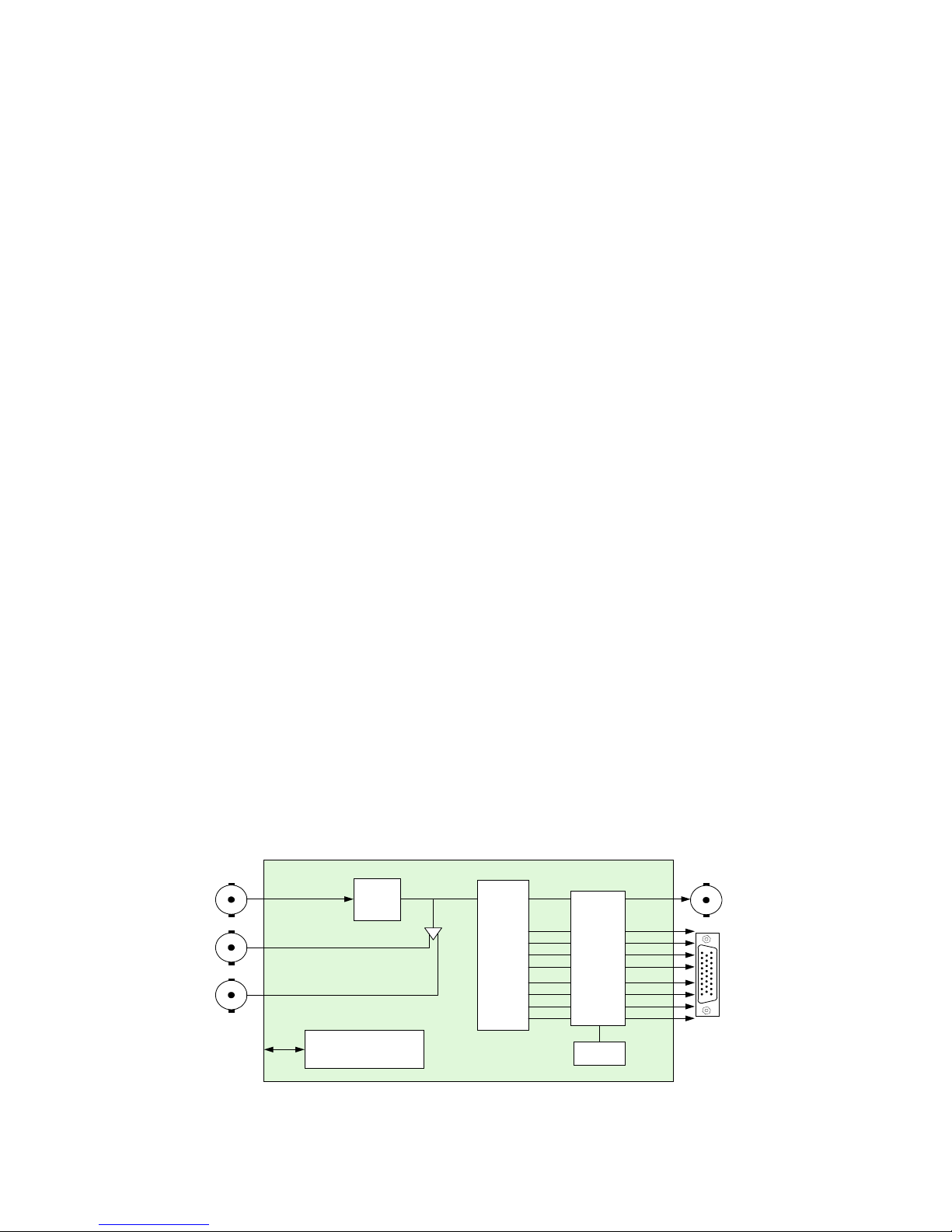
1.3 Schematic Block Diagram
4:2:2 IN
4:2:2
OUT 1
4:2:2
OUT 2
REMOTE
CONTROL
EDH
Microcontroller
ANC
Processor
1
Selectable
Delay
Test Tone
Generator
LTC Out
AES OUT 1
AES OUT 2
AES OUT 3
AES OUT 4
AES OUT 5
AES OUT 6
AES OUT 7
AES OUT 8
Page 8

2 Installation
2.1 Unpacking
Make sure the following items have been shipped with the ADX-102i/104i/108i. If
any of the following items are missing, contact your distributor or Miranda
Technologies Inc.
• ADX-102i, ADX-104i or ADX-108i Digital Audio Demultiplexer
• Rear panel labels
• This manual
2.2 ADX-102i/104i/108i Mechanical Installation
Due to its audio outputs, the ADX-102i/104i/108i must be mounted within QuartetA-75 or Quartet-A-110 or Symphonie imaging frame using Symphonie-R-CX,
Symphonie-R-A75, Symphonie-R-A110 or Symphonie-R-AX rear modules. This
section describes how to install the ADX-102i/104i/108i in any of these frames. It
is not necessary to switch off the power from these frames when installing or
removing the ADX-102i/104i/108i.
2.2.1 Quartet-A-75 and Quartet-A-110 Frame
To install this module into the audio Quartet frames follow these steps. For a
closer look at module installation and removal, refer to the frame's Guide to
Installation and Operation.
1. Remove the frame's front panel by rotating the thumb screws counterclockwise. Pull on the handles.
2. Select an empty slot.
3. Carefully place the ADX-102i/104i/108i between a set of module guides and
gently push the module towards the rear of the frame until the module's edge
connector is secured to the backplane. Pull lightly on the module verifying that
it does not move.
4. Replace the frame's front panel. Make sure to rotate the thumb screws
clockwise in order to secure it to the chassis.
2.2.2 Symphonie Frame
To install this module into the Symphonie housing frame, follow these steps. To
function, the ADX-102i/104i/108i requires the Symphonie-R-CX, -R-A75,-R-A110
or -R-AX rear module. For a closer look at module installation and removal, refer to
the frame's Guide to Installation and Operation.
1. Remove the front panel door by pulling on the door handles and gently
lowering it.
2. Select an empty slot.
3. Carefully place the module between the module guides and slowly push the
module towards the rear of the frame until the module's edge connector is
secured to its rear module. A light pressure to mate the connectors may be
required. Pull lightly on the module verifying that it does not move.
4. Replace the front panel door.
2
Page 9

2.3 Rear Panel Label
Several connector labels have been shipped with the ADX-102i/104i/108i. A label
is to be installed on the frames’ rear panel in order to identify the module's external
connectors.
2.3.1 Quartet-A-75 and Quartet-A-110 Frame
To install the rear panel label on a Quartet-A-75 or a Quartet-A-110 frame, follow
these steps while referring to Figure 2.1 and 2.2.
1. Locate the rear panel connectors associated with the ADX-102i/104i/108i
module.
2. Apply the label to the connectors and press down until it rests onto the BNC
connectors shoulder.
Figure 2.1 Quartet-A-75 rear panel label installation
Figure 2.2 Quartet-A-110 rear panel label installation
3
Page 10

2.3.2 Symphonie Frame
To install the Symphonie label, follow these steps while referring to Figure 2.3.
1. Locate the rear panel connectors associated with the ADX-102i/104i/108i
module. Find the proper label according to your rear module type.
2. Apply the label to the connectors and press down until it rests onto the
BNC connectors shoulder.
Figure 2.3 Symphonie rear panel label installation
4
Page 11

2.4 ADX-102i/104i/108i Electrical Installation
Refer to Figure 2.6 for rear panel electrical installation.
4:2:2 IN: serial digital video input with active loop-through
Connect a 4:2:2 serial digital video source to 4:2:2 IN. The ADX-102i/104i/108i
accepts a 4:2:2 serial digital video signal in either 525 or 625-line format. This
input must conform to the SMPTE 259M-C standard. Make sure the input 4:2:2
cable has a maximum length of 250 m (850'). Refer to section 3.3, Status
Monitoring for a description of error and EDH status on the input signal. The 4:2:2
serial digital loop-through signals are provided by the BNC connector labeled 4:2:2
LOOP. This is an active loop through and does not require termination when not in
use.
Make sure that all serial digital video connections are point-to-point. For instance,
there must be a point-to-point connection between the 4:2:2 IN BNC and the
source equipment. If a T-connector is used to connect other equipment, the
maximum specified cable length is no longer valid.
AES OUT 1 to 4: digital audio outputs (Symphonie-R-CX, Symphonie-R-A75,
or Quartet-A-75 rear panels)
The AES OUT BNC connectors provide unbalanced digital audio signals extracted
from the selected audio group of the 4:2:2 digital video source. These output
signals conform to the AES-3id standard for 75Ω impedance signals. Set jumpers
on card for 75Ω as described in section 2.5 Impedance Selection Jumpers.
AES OUT: digital audio outputs (Symphonie-R-A110, Symphonie-R-AX and
Quartet-A-110 rear panels)
The AES signals, output on the AES OUT HD-26 connector, provide 110Ω
balanced digital audio signals conforming to the AES3 standard. There are eight
AES signals available. Figure 2.4 provides the pinout of the HD-26 rear panel
connector. Set jumpers on card for 110Ω as described in section 2.5 Impedance
Selection Jumpers.
Figure 2.4 AES connector pinout (HD-26)
LTC OUT: linear time code output
When present, the time code signal is extracted and output on the LTC OUT BNC
connector or the HD-15 connector. When output as a balanced signal on the
5
Page 12

HD-15 connector (Figure 2.5) the signal may be used as 2 unbalanced signals or
one side may be grounded. This signal conforms with the SMPTE 12M standard.
Figure 2.5 LTC connector pinout (HD-15)
4:2:2 LOOP : serial digital video output
An active loop-through of the serial digital video signal is provided by the 4:2:2
LOOP connector(s). A single 4:2:2 output is provided when used with Quartet-A75, Quartet-A-110, Symphonie R-A75 or Symphonie R-A110. Symphonie-R-CX or
Symphonie-R-AX provide two 4:2:2 outputs. All outputs conform to the SMPTE
259M-C standard.
Figure 2.6 ADX-102i/104i/108i electrical installation
6
Page 13

2.5 Impedance Selection Jumpers
Depending on the type of rear module used with the ADX-102i/104i/108i, the
proper output impedance selection must be set on the module. When used with an
AES3 rear panel (Symphonie-R-AX, Symphonie-R-A110 or Quartet-R-A-110) set
the impedance jumper to 110Ω. When used with an AES-3id rear panel
(Symphonie R-A75, Symphonie-R-CX or Quartet-A-75) set the impedance jumper
to 75Ω.
1. Referring to Figure 2.7 , locate jumpers LK1, LK2, LK3, LK5, LK6, LK7, LK8
and LK9 at the rear of the ADX-102i/104i/108i module. Jumpers correspond to
AES outputs located above as shown on picture 2.7.
Note: jumpers are not arranged in numerical order.
Figure 2.7 Impedance jumpers location
7
Page 14

3 Operation
3.1 ADX-102i/104i/108i User Interface
Figure 3.1 illustrates the ADX-102i/104i/108i's user interface situated at the front
end of the module. The interface components include the following:
• Digital video input status monitoring
• Audio groups status monitoring
• Embedded LTC status monitoring
• Test signal selection
• 4-character dot matrix display and 4 push-buttons for menu and feature access
Figure 3.1 ADX-102i/104i/108i user interface
3.2 Menu Introduction
Most ADX-102i/104i/108i parameters are accessed and changed via an easy-touse menu. The flow chart of Figure 3.2, 3.3 and 3.4 outlines the entire ADX102i/104i/108i menu path. The menu consists of 7 major functions:
• Embedded audio group selection
• Audio channel swap and/or mute
• Audio and LTC delay selection
• AES channel status information
• Slot selection for cascade operation
• Test signal setup
• Factory reset
Each menu is described throughout this section. The following items should be
remembered when accessing the menu.
8
Page 15

Normal Mode
When the menu is not being accessed we refer to this as normal mode. When in
normal mode, the display is turned off.
Automatic Exit From Menu After 1-Minute Interval
If the menu is currently being accessed and no push-button has been pressed for 1
minute, the ADX-102i/104i/108i automatically exits from the menu thereby returning
to normal mode. Also, changes made to the current parameter will be stored.
Navigating Through the Menu
The front panel push-buttons are used to navigate the menu of Figure 3.2. The
following describes the function of each push-button when navigating through the
menu.
+): Press (+) to move down in the menu or to increase the parameter
(
value. For example, if you are currently at A1-2 in the OUT menu,
pressing (+) will scroll downwards through the selections A3-4, A5-6
and A7-8. Depressing (+) during an adjustment will increase the
parameter value or scroll at a faster rate.
-
(
): Press (-) to move up in the menu or to decrease the parameter value.
For example, if you are currently at A7-8 in the OUT menu, pressing () will scroll upwards through the selections A5-6, A3-4 and A1-2.
Depressing (-) during an adjustment will decrease the parameter value
at a faster rate.
SELECT: Changes to a menu parameter are stored immediately to non-volatile
memory. For example, after the desired A1-2 audio source has been
set, press SELECT. The menu returns to OUT and the new audio
source is stored for the AES1 and AES2 signal pair (A1-2).
ESC: If ESC is pressed after making changes to a parameter, the parameter
is reset to the value it had prior to the change. For example, after
changing the A1-2 audio source, press ESC. The menu is returned to
A1-2 and the previous audio source setting is reloaded.
9
Page 16

Figure 3.2 ADX-108i menu hierarchy
10
Page 17

Figure 3.3 ADX-104i menu hierarchy
11
Page 18

Figure 3.4 ADX-102i menu hierarchy
3.3 Status Monitoring
• 525
The 525 LED turns on to indicate a 525-line serial digital 4:2:2 signal has
been detected on the 4:2:2 IN BNC.
• 625
The 625 LED turns on to indicate a 625-line serial digital 4:2:2 signal has
been detected on the 4:2:2 IN BNC.
12
Page 19

• ERR (Error)
The ERR LED will turn on if no serial digital 4:2:2 signal is input or if an
input error has been detected. Make sure the source signal is properly
connected to 4:2:2 IN and verify for any source equipment errors.
• EDH (Error Detected Here)
This LED turns on to indicate a serial data transmission error has been
detected.
• Test
This LED turns on to indicate that test signals are selected to the outputs.
• Audio groups 1 to 4
These LEDs turns on to indicate which digital audio groups have been
detected in the 4:2:2 IN input signal.
• LTC
This LED turns on to indicate that sampled LTC signal has been detected
in the 4:2:2 IN input signal.
• DVITC
Reserved for future release.
3.4 Digital Audio Disembedding Selection
AES/EBU digital audio pairs can be disembedded from any of four groups within
the selected ancillary data space of the 4:2:2 digital video signal (see section 3.10
for ancillary data space selection). Perform the following steps in order to select
the group to disembed for any of the 8 audio signal pairs:
1. Press SELECT to enter the menu. OUT is displayed.
2. Press SELECT to enable the audio group selection menu. The current audio
group from which to disembed the AES pair is displayed (GRP1 through
GRP4).
3. Press (+) or (-) to change the audio group selection. If you wish not to change
the audio group selection, select ESC.
4. Press SELECT to enable the AES digital audio source selection. The currently
selected source is displayed. Press (+) or (-) to change the audio source
selection.
5. Press SELECT to store the new audio group selection and return to OUT.
6. To return to normal mode, press ESC again
(OUT-> A1-2 to A7-8)
13
Page 20

3.5 Linear Time Code Extraction
Follow these steps to extract sampled LTC from the selected ancillary data space
(see section 3.10 for ancillary data space selection) of the video input LTC (SAMP)
and output as LTC; alternatively, no LTC signal may be output (NONE).
1. Press SELECT to enter the menu. OUT is displayed.
2. Press the (+) push-button until LTC is displayed.
3. Press SELECT to enable the LTC insertion menu. The current LTC
insertion setting is displayed.
4. Press (+) or (-) to set the desired setting. Press SELECT to store the new
setting and return to LTC.
5. To return to normal mode, press ESC twice.
(OUT->LTC)
3.6 Digital Audio Channels Swap/Mute Selection (AES->AES1 to AES2/4/8)
The AES menu allows to mute and/or swap Left-Right channel for each AES output
signal. Follow these steps to apply these functions:
1. Press SELECT to enter the menu. OUT is displayed.
2. Press the (+) push-button until AES is displayed.
3. Press SELECT to enable the AES menu. AES1 is displayed.
4. Press the (+) or (-) push-button until the desired AES signal is displayed.
5. Press SELECT to access the SWAP and MUTE functions. SWAP is displayed.
6. Press SELECT to enable the SWAP menu. Press (+) or (-) to display ON (and
swap left and right channels) or OFF. Press SELECT to store the new channel
swap setting for the selected AES signal and return to SWAP.
7. Press the (+) push-button once to display the MUTE function.
8. Press SELECT to enable the MUTE menu. Press (+) or (-) to select ON (and
mute audio channels) or OFF. Press SELECT to store the new mute setting
for the selected AES signal and return to MUTE.
9. To return to normal mode, press ESC twice.
3.7 Validity Bit Processing
This function allows the card to force the setting of the validity bit (V-Bit) if an error
is detected on the input signal. If this function is not set then the V-Bit already
present on the input signal is passed through unmodified.
1. Press SELECT to enter the menu. OUT is displayed.
2. Press the (+) push-button until AES is displayed.
3. Press SELECT to enable the AES menu. AES is displayed. Press (+)
pushbutton until VBIT is displayed.
4. Press SELECT to enable the VBIT menu. The current VBIT setting is
displayed. Press (+) or (-) to display MUTE (to allow the card to set the V-Bit)
or PASS (to leave the V-Bit unmodified).
5. Press SELECT to store the V-Bit setting and return to VBIT.
6. To return to normal mode, press ESC twice.
(AES-> VBIT)
14
Page 21

3.8 Audio and Time Code Delay
It is possible to add an audio delay of up to 6 fields, by steps of one field. The time
code may be set to track the audio when a delay is applied. To add audio delay,
follow these steps:
7. Press SELECT to enter the menu. OUT is displayed.
8. Press the (+) push-button until DLY is displayed.
9. Press SELECT to enable the delay menu. AES is displayed.
10. Press SELECT to enable the AES delay menu. The current audio delay
setting is displayed.
11. Press (+) or (-) to set the desired delay or NONE. For a quicker response,
keep the push-button depressed. Press SELECT to store the new delay and
return to AES.
12. Press (+) once to select LTC.
13. Press SELECT to enable the LTC delay menu. The current LTC delay setting
is displayed.
14. Press (+) or (-) to set the LTC timing to track the audio (TRAK) or NONE.
Press SELECT to store the new setting and return to LTC.
15. To return to normal mode, press ESC twice.
3.9 Channel Status Information
This menu is used to display channel status information of the AES output signals.
Different information can be displayed for each AES signal.
Note: these settings follow the information disembedded from the 4:2:2 signal.
BITS: Indicates the encoded audio sample word length for the AES channel:
16, 20 or 24 bits, or OTHR for other sample word length (17, 18, 19, …
bits)
MODE: Indicates if the channel is non-stereo (1 CH), stereo (ST), has distinct
left and right audio signals (2 CH) or has a primary and secondary
audio signal (P/S). When mode is not indicated N.I. is displayed.
EMPH: Indicate the type of emphasis used to encode the audio signal: 50-15
us (5015), J17 or none (NONE) if no emphasis is inserted. When
emphasis is not indicated N.I. is displayed.
USE: Indicates the use of channel status block: professional (PRO) or
consumer (CONS).
Follow these steps to add these information:
1. Press SELECT to enter the menu. OUT is displayed.
2. Press the (+) push-button until STAT is displayed.
3. Press select to enable the STAT selection menu. AES1 is displayed.
4. Press the (+) or (-) push-button until the desired AES audio output is
displayed.
5. Press SELECT to access the channel status information settings. BITS is
displayed.
6. Press SELECT to enable the BITS menu. The current audio sample word
length for the selected audio signal pair is displayed.
7. Press ESC return to BITS.
8. Press the (+) push-button once to display the next channel status
information.
(DLY)
(STAT -> AES1 to AES2/4/8)
15
Page 22

9. Repeat step 6 to 8 for each status information.
10. To return to normal mode, press ESC twice.
3.10 Embedded Audio Location
Normally the audio groups are embedded into the HANC area of the 4:2:2 signal
per SMPTE 272M. Miranda has expanded on this capability by permitting
embedders to be cascaded and to also embed audio groups into time slots in the
active picture area.
This menu allows the selection of the location from which the AES signals will be
extracted. The AES signals may have been inserted into the normal HANC data
space and/or into the active picture area as in the case of cascading signal
embedding. Since there are five ANC available “slots” in the active picture area in
addition of the HANC data space, you need to specify the location of the AES
digital audio signals. To select the location from which to extract AES digital audio
signals, follow these steps:
1. Press SELECT to enter the menu. OUT is displayed.
2. Press the (+) push-button until SLOT is displayed.
3. Press SELECT to enable the slot location menu. The current embedded
audio slot location setting is displayed.
4. Press (+) or (-) to select the desired slot. Press SELECT to store the new
setting and return to SLOT.
5. To return to normal mode, press ESC.
(SLOT)
3.11 EBU Test Tone Generator Selection
An internal EBU tone generator provides a steady –18 dBFS 1 KHz continuous
tone on the right channels and a pulsed –18 dBFS 1 KHz tone on the left channels.
To enable the tone generator, follow these steps:
1. Press SELECT to enter the menu. OUT is displayed
2. Press the (+) push-button until TEST is displayed.
3. Press SELECT to enable the tone generator menu. AES is displayed.
4. Press (+) or (-) to display the tone generator options. The menu offers the
options to output a tone on all channels or on selected AES channels
(AES1 to AES8), or disable the tone generator (OFF).
5. Press SELECT to store the new setting and return to AES.
6. To return to normal mode, press ESC twice.
Once the test signals have been selected and the menu returned to normal
mode, the test outputs are pre-selected. By using the (+) push-button you may
toggle test signals on and off for the selected AES channels. Depress it once
and the LED turns on; the test tone is enabled at the output. Depress it again
and the LED turns off, disabling the test tone.
(TEST)
16
Page 23

3.12 Factory Reset
It may be necessary, at times, to reset all parameters to their original values
programmed during manufacturing. Tables 3.1 to 3.3 list the default values. To
perform a factory reset follow these steps.
1. Press SELECT to enter the menu. GRP is displayed.
2. Press the (+) push-button until FACT is displayed.
3. Press SELECT to enter the FACT menu. NO is displayed.
4. Press the (+) push-button to display YES.
5. Press SELECT to reset all parameter values to factory values. After the reset
is complete, the menu returns to FACT.
6. Press ESC to return to normal mode.
Table 3.1 ADX-108i - Parameter values after a factory reset
Menu Items
Group extracting selection:
LTC Insertion:
AES channel swap and mute:
Audio and time code delay:
Audio embedding location:
Test signal generation:
Table 3.2 ADX-104i - Parameter values after a factory reset
Menu Items
Group extracting selection:
LTC Insertion:
AES channel swap and mute:
Audio and time code delay:
Audio embedding location:
Test signal generation:
Table 3.3 ADX-102i - Parameter values after a factory reset
Menu Items
A1-2:
A3-4:
A5-6:
A7-8:
None
AES1 to AES8: SWAP:
AES:
LTC:
HANC
AES: OFF
A1-2:
A3-4:
None
AES1 to AES4: SWAP:
AES:
LTC:
HANC
AES: OFF
Default
Settings
GRP1
GRP2
GRP3
GRP4
OFF
MUTE:
NONE
GRP1
MUTE:
NONE
OFF
NONE
Default
Settings
GRP2
OFF
OFF
NONE
Default
Settings
17
Page 24

Group extracting selection:
LTC Insertion:
AES channel swap and mute:
Audio and time code delay:
Audio embedding location:
Test signal generation:
A1-2: GRP1
None
AES1 and AES2: SWAP:
MUTE:
AES:
NONE
LTC:
OFF
OFF
NONE
HANC
AES: OFF
18
Page 25

4 Specifications
Input
Video signal 4:2:2 SMPTE 259M-C (270Mbps)
With audio per SMPTE 272M-C
Sampled LTC embedded per SMPTE 291M
Cable length: 250 m (850’) (Belden 8281)
Return loss: >15 dB up to 270 MHz
Output
Video signals (3): 4:2:2 SMPTE 259M-C (270Mbps)
Return loss: >15 dB up to 270 MHz
Jitter (wideband): < 0.2 UI (0.74 ns) p-p
Audio
AES-3id
Signal (2/4): AES-3id (SMPTE 276M)
48 kHz, synchronous to input video signal
Level: 1.0 Vp-p
Impedance: 75 Ω unbalanced
Return loss: >25 dB up to 6 MHz
AES3
Signal (2/4/8): AES3
48 kHz, synchronous to input video signal
Level: 3.5 Vp-p
Impedance: 110 Ω balanced
LTC signal: Reconstruction of LTC input to ADX-102i/104i/108i
Level: 1 Vp-p
Processing performance
Signal path: 10-bit video/24-bit audio
Sampling rate: 48 KHz synchronous
Processing delay: Video: 520 ns
Audio: 320 µs (640 µs combined with AMX-108i)
Sampled LTC: 515 µs (580 µs combined with ADX-108i)
Audio delay: Up to 6 video fields (Field steps)
LTC delay: Up to 6 video fields (Field steps)
Test signals: Video - 75% color bars with 100% white
Audio - 1 kHz tone –18dBFS (R steady, L pulsed 0.25s/3s)
Miscellaneous
Storage temperature: -40 to 85°C
Operating environment: 0 to 40°C, non-condensing
Humidity: 10 to 90%, non-condensing
Power consumption: 6 W
Physical format: imaging size (6.0”x10.0”)
Remote control: ICP-S (Miranda proprietary serial bus)
(EBU R49 & R68)
19
 Loading...