

Miranda AAP-1741 Installation Manual

DENSITÉ series
AAP-1741
Four Channel Analog Audio Processor
Guide to Installation and Operation
M768-8200-100
6 Jun 2007
Miranda Technologies Inc.
3499 Douglas-B.-Floreani
St-Laurent, Québec, Canada H4S 1Y6
Tel. 514-333-1772
www.miranda.com
© 2007 Miranda Technologies Inc..
Fax. 514-333-9828

GUIDE TO INSTALLATION AND OPERATION
Safety Compliance Information
Safety Compliance
This equipment complies with:
- CSA C22.2 No. 60950-1-03 / Safety of Information Technology Equipment, Including Electrical Business Equipment.
- UL 60950-1 (1
- IEC 60950-1 (1
CAUTION
These servicing instructions are for use by qualified service personnel only. To reduce the risk of electric shock, do not
perform any servicing other than that contained in the operating instructions unless you are qualified to do so. Refer all
servicing to qualified service personnel. Servicing should be done in a static-free environment.
Electromagnetic Compatibility
- This equipment has been tested for verification of compliance with FCC Part 15, Subpart B, class A requirements for
Digital Devices.
- This equipment complies with the requirements of:
EN 55022 Class A, Electromagnetic Emissions,
EN 61000-3-2 & -3-3, Disturbance in Supply Systems
EN 61000-4-2, -3, -4, -5, -6, -8 & -11 Electromagnetic Immunity
How to contact us:
For technical assistance, please contact the Miranda Technical support centre nearest you:
Americas
Telephone:
+1-800-224-7882
e-mail:
techsupp@miranda.com
Visit our web site at www.miranda.com
st
Edition) / Safety of Information Technology Equipment, Including Electrical Business Equipment.
st
Edition) / Safety of Information Technology Equipment, Including Electrical Business Equipment.
Asia
Telephone:
+81-3-5730-2987
e-mail:
asiatech@miranda.com
Europe, Middle East,
Africa, UK
Telephone:
+44 (0) 1491 820222
e-mail:
eurotech@miranda.com
France (only)
Telephone:
+33 (0) 1 55 86 87 88
e-mail:
eurotech@miranda.com
AAP-1741

GUIDE TO INSTALLATION AND OPERATION
Table of Contents
1 AAP-1741 Four Channel Analog Audio Processor..................................................................1
1.1 Introduction ......................................................................................................................................... 1
1.2 Features .............................................................................................................................................. 1
1.3 Applications......................................................................................................................................... 2
1.4 Functional Block diagram.................................................................................................................... 2
1.5 Card front-edge layout ........................................................................................................................ 3
2 Installation ..................................................................................................................................4
2.1 Unpacking ........................................................................................................................................... 4
2.2 Installation in the Densité frame.......................................................................................................... 4
2.2.1 Rear Panel Options................................................................................................................ 4
3 Operation ....................................................................................................................................5
3.1 Control options .................................................................................................................................... 5
3.2 Local control using the Densité frame control panel........................................................................... 5
3.2.1 Status LED............................................................................................................................. 6
3.2.2 Menu for local control............................................................................................................. 7
3.3 Remote control using iControl........................................................................................................... 10
3.3.1 Audio Processing ................................................................................................................. 12
3.3.2 Dynamic Processing ............................................................................................................ 14
3.3.3 Audio Output ........................................................................................................................ 16
3.3.4 UP/DOWN MIX ....................................................................................................................18
3.3.5 Audio Type........................................................................................................................... 21
3.3.6 RALM tab: ............................................................................................................................ 22
3.3.7 A-BUS .................................................................................................................................. 23
3.3.8 Reference Input.................................................................................................................... 24
3.3.9 Rear Type ............................................................................................................................ 25
3.3.10 Factory / Presets.................................................................................................................. 25
3.3.11 Options................................................................................................................................. 27
3.3.12 Alarm Configuration .............................................................................................................27
3.3.13 Info ....................................................................................................................................... 28
4 Specifications...........................................................................................................................29
AAP-1741

GUIDE TO INSTALLATION AND OPERATION
AAP-1741

GUIDE TO INSTALLATION AND OPERATION
1 AAP-1741 Four Channel Analog Audio Processor
1.1 Introduction
The AAP-1741 is a four-channel high quality audio processor designed to work alone or with a wide range
of video converters, frame synchronizer proc/amps of the Densité series.
The card features two distinct processing blocks: Input and Output. The input processing includes Dolby
detection, Tone generator, delay adjustments, level controls and phase correction. Delay components
include a fixed delay of up to 2 seconds as well as a video tracking delay that will automatically track the
varying saw tooth delay introduced by an associated video frame synchronizer.
The output processing block includes full channel shuffling, an additional gain/attenuation stage and
mixing. Each odd output channel is a mix of any two input channels, and a 4-channel mixing is available
on the even output channels.
Additional audio functions such as dynamic processing (compressor/limiter and expander) and/or Down
and Up mixing are proposed as options.
With a card-to-card Audio bus, the AAP-1741 provides processing for 8 channels originating from a video
card. Once processed, the signals are sent back to be embedded, and are also available at the analog
outputs.
Along with the audio channels, the Audio bus carries the timing, delay signaling and Dolby Metadata.
When combining cards together all audio processing is synchronous and in phase, ensuring proper
alignment and matched delay. The AAP-1741 can work with one video card and/or one other audio
processor card.
An input audio signal status is also available indicating the input signal presence or overload.
The card is housed in a (DENSITÉ) frame, with a single or double width rear connector panel.
.
1.2 Features
• 8 channel processing of embedded audio signals.
• Stand-alone 8 channel audio processor and delay.
• Fixed delay and up to 8 video frames tracking delay
• Full channel shuffling on the outputs
• 2 and 4 channel mix-down
• Audio metering data for audio levels and phase over IP.
• Dolby E compatibility
• Analog audio inputs and outputs
• Full quality 24 bit audio converters
• Balanced AES3 or unbalanced AES3-id I/Os
• -96 to +12 dB of input and output level adjustments (0.5 dB steps)
• Separate input and output 0 dBFS adjustments (0 to +24 dBu, 1 dB steps)
• Locks to video card, frame reference or AES input
AAP-1741 | 1
GUIDE TO INSTALLATION AND OPERATION
• Internal digital EBU tone generator
• Absence signal delay and threshold adjustable /channel
• Overload detection
• All settings through frame control panel or remotely
• Status LED and alarms remote reporting
1.3 Applications
• With a DEC-1xxx in Incoming feeds applications as A to D converter and audio processor.
• Companion to an ENC-1xxx as an audio proc and a final D to A converter.
• Stand-alone or associated with an FRS-1xxx as an audio processor with analog inputs and outputs.
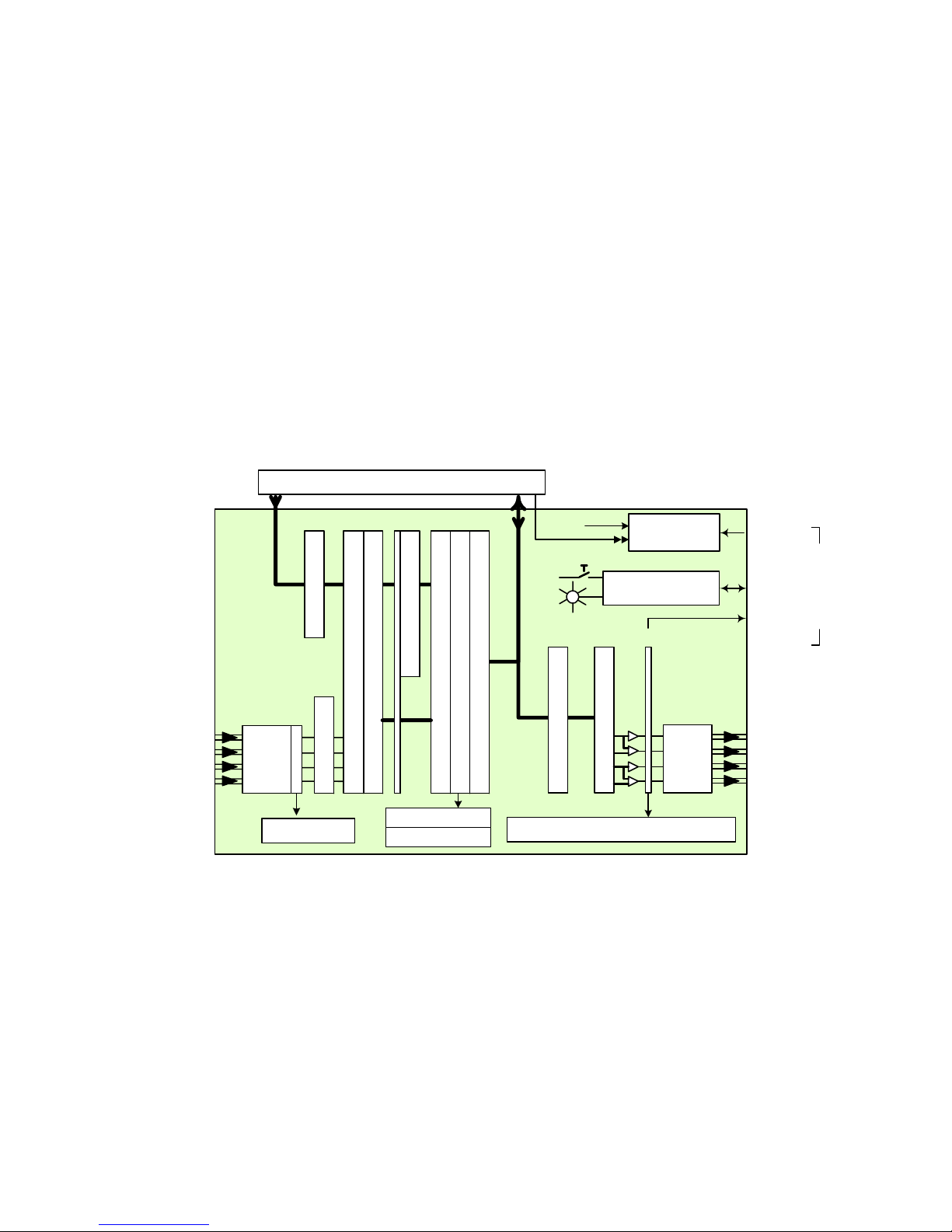
1.4 Functional Block diagram
Analog
Inputs
.
L1
R1
L2
R2
ABUS IN
16
4 x
ADC
4 x Overload
ABUS
INPUT PROCESSOR
8
ABUS Select
Up or Down Mixer
Tone
Dolby Detection
L & R Swap
16 x No Signal
16 x Overload
Video card / audio cards link
From DIR1
VIDEO
Select
ABUS OUT
Status
OUTPUT PROCESSOR
Reference
Microcontroller
Ref. IN
Remote
Control
Monitor
OUT
Intra Frame
16
Phase & Level
Fixed & Variable Delay
48
Compressor - Limiter - Expander
4 x Peak meters, 2 x Phase meters
8
8x Level
48 x 8 Schuffler
4 x
DAC
L1
Analog
R1
L2
Outputs
R2
2 | AAP-1741
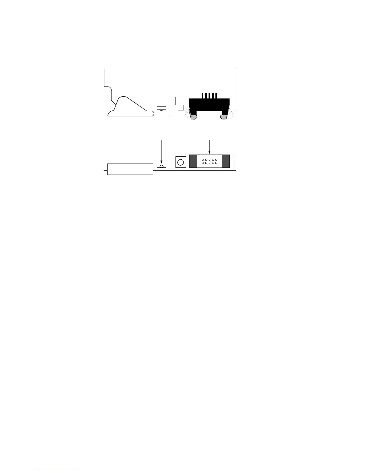
1.5 Card front-edge layout
GUIDE TO INSTALLATION AND OPERATION
SW1
D1
SELECT
STA TUS
Status Led
ABUS connector
Select
Button
AAP-1741
AAP-1741 | 3
GUIDE TO INSTALLATION AND OPERATION
2 Installation
2.1 Unpacking
Make sure you have ordered and received the AAP-1741 and its associated rear panel. If any of the
following items are missing, contact your distributor or Miranda Technologies Inc.
• AAP-1741 4-Channel Analog Audio Processor
• One of the AAP-1741 Rear Panels (see figure)
• An ABUS flat cable
2.2 Installation in the Densité frame
The AAP-1741 must be mounted in a DENSITÉ frame. The installation includes both the AAP-1741
module, and the rear panel module. It is not necessary to switch off the frame’s power when installing or
removing the card.
When the AAP-1741 is used in conjunction with a video module such as FRS-1101 and/or another audio
module like AAP-1741 or UAP-1783, the ABUS flat cable must be installed between the ABUS
connectors.
• Note: for a two card installation, use the two end connectors of the flat cable and leave the
middle one unplugged.
Detailed instructions for installing cards and their associated rear panels in the Densité frame are given in
the Densité Frame manual.
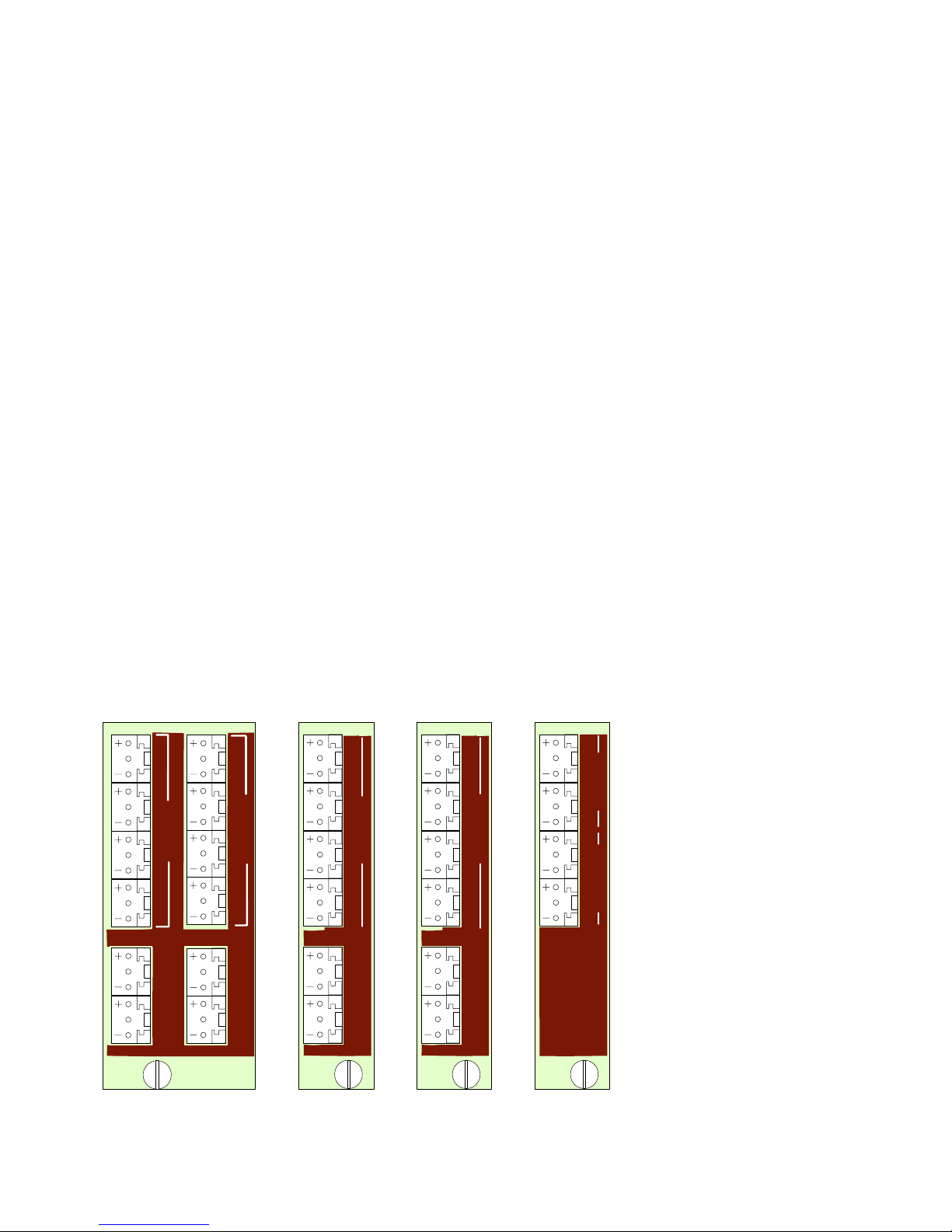
2.2.1 Rear Panel Options
1A
+ G - + G -
1L
1R
ANALOG IN
+ G -
2L
+ G -
2R
N.C.
N.C.
2 RIGHT
2A
+ G - + G -
+ G -
ANALOG OUT
+ G -
1A
AAP-1741-DRP
N.C. N.C.
1R
+ G -
N.C. N.C.
1L
+ G - + G -
2L
+ G -
2R
ANALOG IN
AAP-1741-I-SRP
1A
1L
+ G - + G -
1R
ANALOG OUT
2L
+ G -
2R
+ G -
AAP-1741-O-SRP
N.C. N.C.
1A
1L
1R
1L
+ G - + G -
1R
+ G -
+ G -
ANALOG OUTANALOG IN
AAP-1741-SRP
4 | AAP-1741
GUIDE TO INSTALLATION AND OPERATION
3 Operation
3.1 Control options
The AAP-1741 has two primary control interfaces:
• The local control panel attached to the Densité frame’s controller
• Remote control using Miranda’s iControl system
These will be explained in detail in the following sections.
3.2 Local control using the Densité frame control panel
Push the SELECT button on AAP-1741 card edge (see Section 1.5) to assign the local control panel to
operate the AAP-1741. Use the control panel buttons to navigate through the menu, as described below.
All of the cards installed in a Densité frame are connected to the frame’s controller card, which handles all
interaction between the cards and the outside world. There are no operating controls located on the cards
themselves. The controller supports remote operation via its Ethernet ports, and local operation using its
integrated control panel.
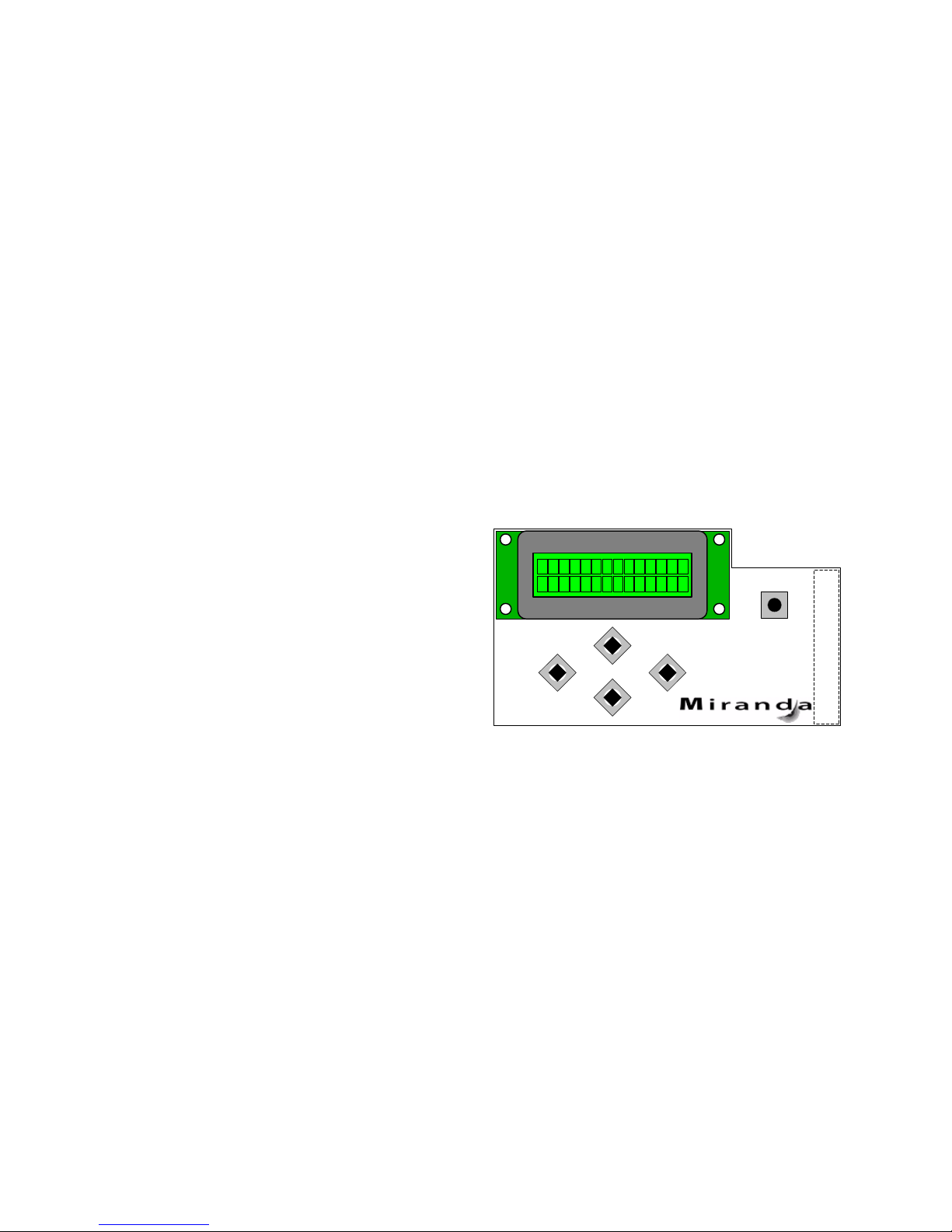
The local control panel is fastened to the controller
card by a hinged connector, and when installed is
located in the front center of the frame, positioned in
front of the power supplies. The panel consists of a
display unit capable of displaying two lines of text,
each 16 characters in length, and five pushbuttons.
The panel is assigned to operate any card in the frame
by pushing the SELECT button on the front edge of
that card. Pushing the CONTROLLER button on the
control panel selects the Controller card itself. The
STATUS LED on the selected card flashes yellow.
The local control panel displays a menu that can be navigated using the four pushbuttons located beneath
the display. The functionality of the pushbuttons is as follows:
[CTRL] Selects the controller card for status monitoring and adjustment
[+] [–] Used for menu navigation and value modification
[SELECT] Gives access to the next menu level. When a parameter value is shown, pushing this button
once enables modification of the value using the [+] and [–] buttons; a second push confirms the
new value
[ESC] Cancels the effect of parameter value changes that have not been confirmed; pushing [ESC]
causes the parameter to revert to its former value.
Pushing [ESC] moves the user back up to the previous menu level. At the main menu, [ESC]
does not exit the menu system. To exit, re-push the [SELECT] button for the card being
controlled.
If no controls are operated for 30 seconds, the controller reverts to its normal standby status, and the
selected card’s STATUS LED reverts to its normal operating mode.
ESC
+
-
CONTROLLER
SELECT
AAP-1741 | 5

GUIDE TO INSTALLATION AND OPERATION
3.2.1 Status LED
The status monitor LED is located on the front card-edge of the AAP-1741, and is visible through the front
access door of the DENSITÉ frame. This multi-color LED indicates module status by color, and by
flashing/steady illumination, according to the chart. The chart also indicates fault reporting for this card on the
DENSITÉ frame’s serial and GPI interfaces.
Serial
Report
Card system error
Not expected reference Error
Reference error
NSD CH 1 to 4 Analog input
NSD CH 9 to 16 (Ext.CH 1/8 or 9/16)
OVERLOAD CH 1 to 4 analog inputs
OVERLOAD CH 1 to 16 processing
OVERLOAD analog outputs 1 to 4
Any TONE activated
Any output Mute
GPI
Report Green Yellow Red
Flashing
Red
-
-
-
-
-
User attention - - - - - - Yes
Rear panel error - - - - - Yes FPGA error - - - - - Yes
Flashing
Yellow
-
: Factory default.
Note: The non-requested message posting to an alarm status can only be accessed by the
communication protocol (serial port)
NOTE: A “Flashing Yellow” Status LED indicates that the SELECT button on the front panel has been
pushed.
6 | AAP-1741
 Loading...