

Page 1

CONTENTS
INTRODUCTION....................................................1
FEATURES............................................................. 1
SPECIFICATIONS..................................................2
EXPLANATION OF FEATURES...........................3-5
INSTALLATION.................................................... 6
DIAGRAM OF RX GAIN....................................... 7
B-24-G OPTIONAL ADAPTORS........................... 8-9
PRECAUTIONS...................................................... 10-11
CONNECTION DIAGRAM.....................................12
B-24-G BOOSTER AMP. BLOCK CIRCUIT..........13
WARRANTY...........................................................14
Page 2

INTRODUCTION
The B-24-G is a VHF band high power linear amplifier
designed for the 144 MHz band. It has a maximum output power
of 50W.
With a combination of built-in low noise GaAsFET
receive pre-amp, the B-24-G enables you to enjoy a more
comfortable VHF DX QSO.
FEATURES
1. High output power of 50W.
50W average is achieved with 1~5W input power.
2. Aluminum heat sink.
Aluminum heat sink combined with the case is designed
or an excellent heat dissipation effect.
-- -- 1
Page 3

SPECIFICATION
FREQUENCY : 144 MHz
MODE : F3 (FM)
INPUT POWER : 1-5W
D.C. OUTPUT POWER : 50W
DC POWER SUPPLY : DC 13.8V
OUTPUT CONSUMPTION : 8A (MAX.)
INPUT/OUTPUT IMPEDANCE : 50 Ohm
INPUT/OUTPUT CONNECTOR : BNC/M TYPE
RX GAIN : 18 dB
ACCESSORY CIRCUIT : COX (Carrier Operated
T/R switch, RX pre-amp)
ACCESSORIES : Mobile mounting bracket,
FUSE (8A), Instruction
Manual, docking adaptor.
DIMENSIONS : 3.4(W)*6.0(H)*3.4(D)in
WEIGHT : approx. 1.5 lbs.
-- -- 2
Page 4
EXPLANATION OF FEATURES
-- -- 3
Page 5

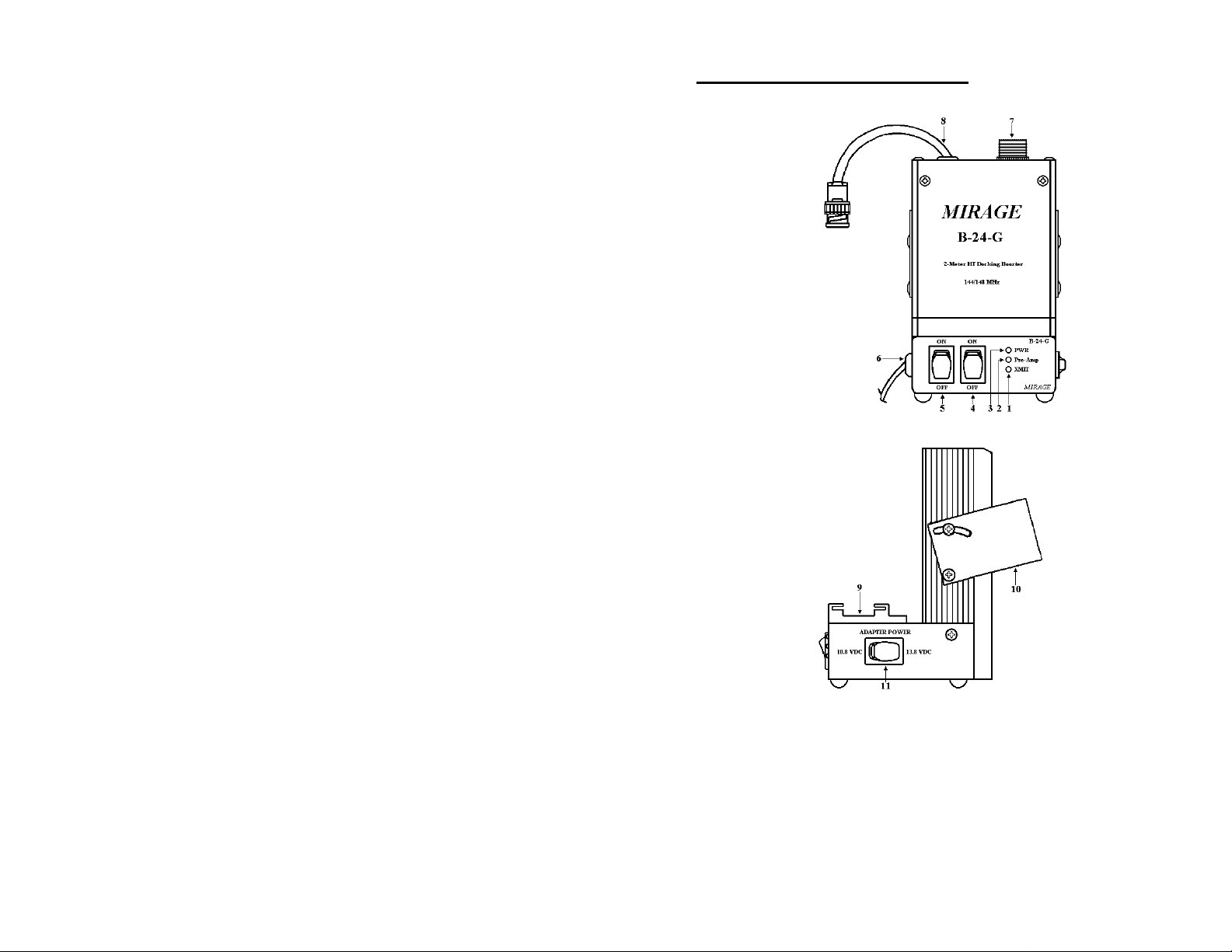
1. PWR INDICATOR
The PWR Indicator LED indicates the amplifier is
transmitting or on air.
2. PRE-AMP INDICATOR
When the PRE-AMP Indicator LED is on, it indicates the
amplifier is in the RX mode and boosts the signal
received.
3. TX INDICATOR
The TX Indicator LED indicates the amplifier is ON and
in Stand-By mode. The amplifier is now ready to
transmit.
4. PRE-AMP/OFF SWITCH
When this switch is ON (upper position), the pre-amp
unit boosts the signal received.
5. TX/OFF SWITCH
ON (upper position): The amplifier is ready to transmit.
(Max. 50W)
OFF (lower position): The amplifier is on receive mode
only.
6. DC INPUT (13.8V)
This port has two wires. Connect it to a stable DC power
supply (13.8V) or battery. The red wire has a fuse holder
and is the positive lead. The black wire is the negative
lead. (FUSE holder is on the positive DC lead.)
-- -- 4
Page 6

7. ANT
The Antenna can be connected directly here.
8. TX (RF INPUT)
This is a BNC connector that should be connected
directly to the handy-transceiver.
9. DOCKING ADAPTOR
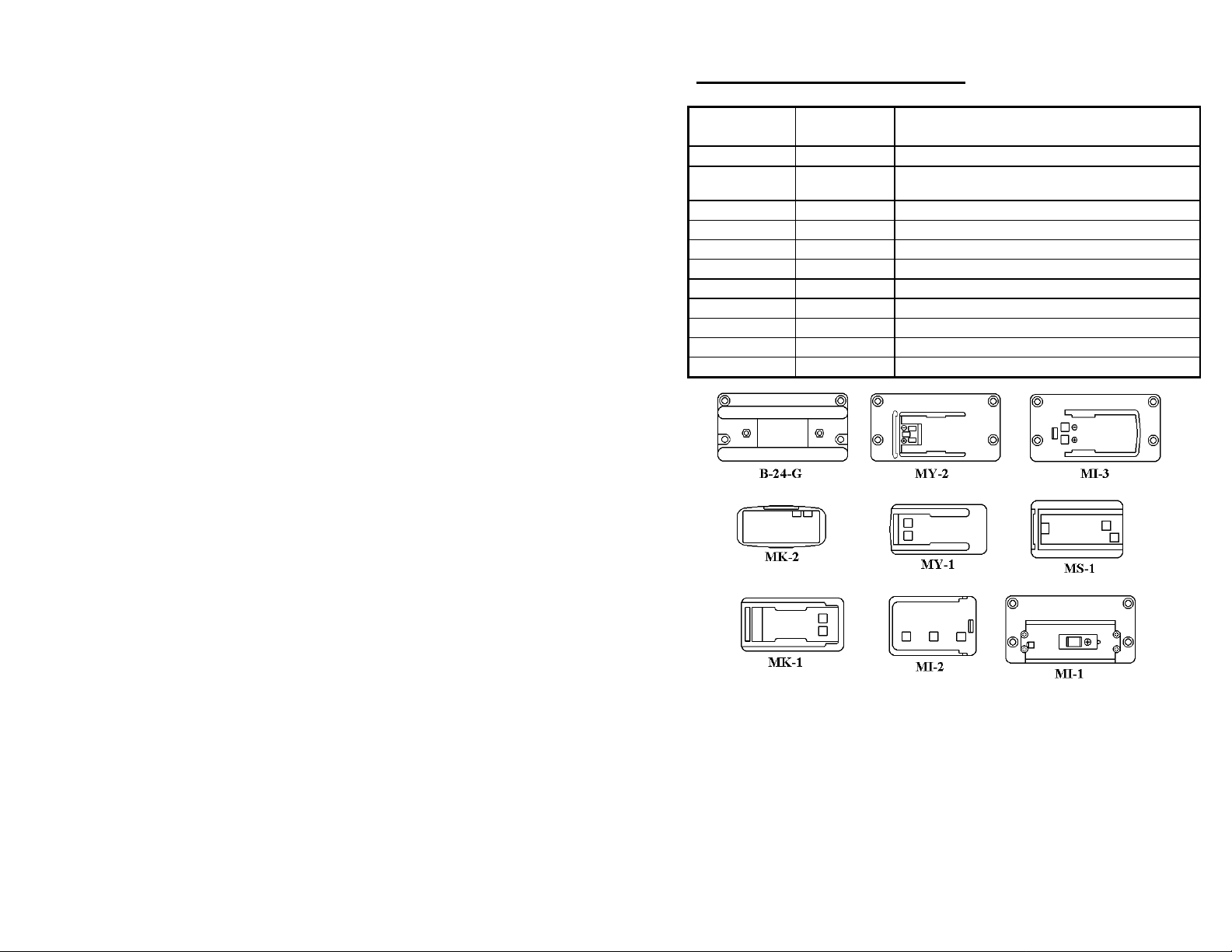
There are various adaptors suitable for different models
of handy-transceivers.
10. MOUNTING BRACKET
The mounting bracket allows easy attachment of your
B-24-G to your car.
11. ADAPTER POWER SWITCH
The adaptor power can be turned OFF (middle position)
when the amplifier is not in use. You can select the
adaptor to be 10.8V (left position) for new HT models or
13.8V (right position) for older models depending on
your HT.
-- -- 5
Page 7
INSTALLATION
-- -- 6
Page 8
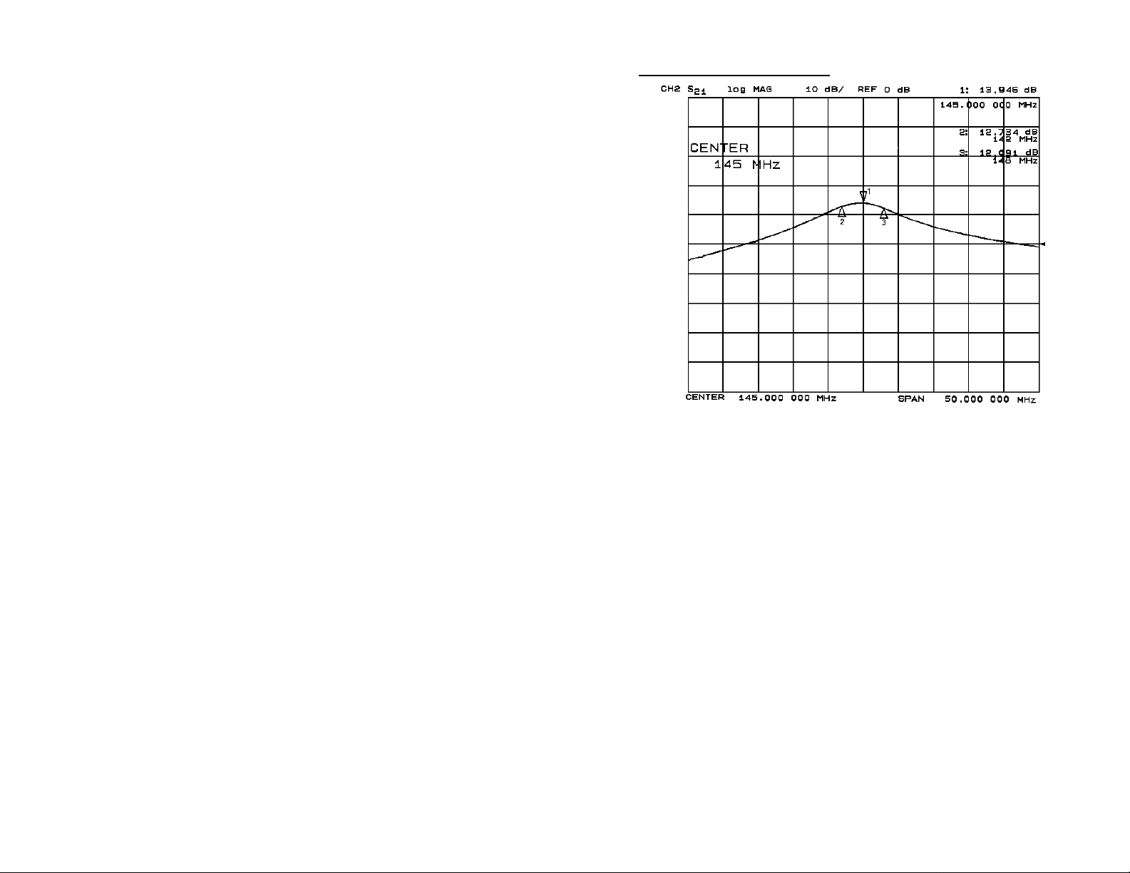
DIAGRAM OF RX GAIN
-- -- 7
Page 9
B-24-G OPTIONAL ADAPTORS
HAM RADIO
MAKER
ICOM MI-1
ICOM MI-2
ICOM MI-3
ICOM MI-4
YAESU MY-1
YAESU MY-2
YAESU MY-3
YAESU MY-4
KENWOOD MK-1
KENWOOD MK-2
STANDARD MS-1
ADAPTOR
MODEL
COMPATIBLE TRANSCEIVER MODEL
NO.
IC-2N, 02N, 3N, 03N, 12N, 2G, 3G, 12G, 23, etc.
IC-2S, 2SAT, 2SR, 3S, 3SAT, 3SR, 24, W2, X2,
etc.
IC-W21, X21, W21T, X21T etc.
IC-T22, T42
FT-23, 204, 73, 704, 104, 728, etc.
FT-24, 74, 205, 705, 305, 805, 729, etc.
FT-11
FT-50
TH-25, 25G, 45, 45G, 55, 75,77, etc.
TH-22A, 22AT, 42A, 42AT, 59, 79, 79E, etc.
C150, C450, C520, C550, 620, etc.
-- -- 8
Page 10
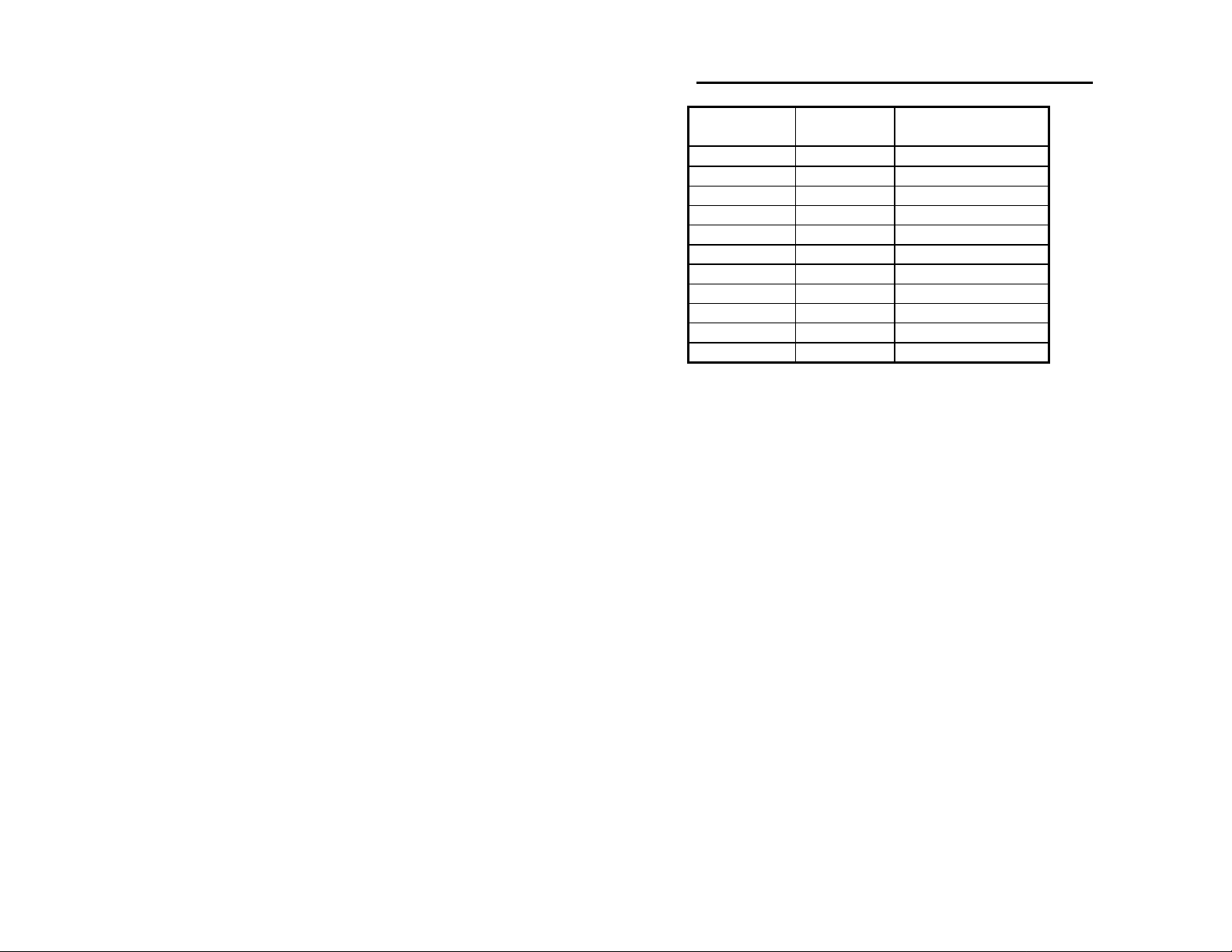
ADAPTORS and ADAPTOR POWER SETTING
HAM RADIO
MAKER
ICOM MI-1 13.8
ICOM MI-2 13.8
ICOM MI-3 13.8
ICOM MI-4 10.8
YAESU MY-1 10.8
YAESU MY-2 13.8
YAESU MY-3 10.8
YAESU MY-4 10.8
KENWOOD MK-1 10.8
KENWOOD MK-2 10.8
STANDARD MS-1 13.8
ADAPTOR
MODEL
ADAPTOR POWER
SETTING
-- -- 9
Page 11

PRECAUTIONS
To avoid malfunctions and damages, and to achieve full
performance, please pay careful attention to the following
matters:
1. During transmission, the heat sink may reach a high
temperature (approx. 50°C-80°C). Set the amplifier in a
well- ventilated place. Do not place objects on top of the
amplifier. Do not operate the amp in places exposed to
direct sunlight or close to a heater, etc.
2. If the antenna matching condition is poor (or the SWR is
high), please try to lower the SWR. This is also
important to ensure the efficient transmitting of output
power from the antenna. Also, check make sure the
antenna is properly connected and there is no short or
open before operation.
3. Keep the input power at 5W or less.
4. Be careful that the DC voltage is kept below 13.8V (12
14V). The amplifier could be damaged is connected to a
DC 24V battery (for truck use) or AC power source.
-- -- 10
Page 12

5. Never connect the whip antenna of a handy-transceiver
directly to the antenna connector of the amplifier unit
using M-BNC converting connector etc. It may cause
damage to the antenna due to insufficient power capacity.
It may also damage the transceiver or the amplifier when
strong RF signal intrusions occur.
6. Be sure to use a 50Ω coaxial cable for the various
connections. When the impedance differs as with a 75Ω
cable, reflected waves will cause a mis-match. This
condition makes it difficult to achieve full power from
the amplifier and it may cause the RF power transistor to
be damaged.
7. When using a stabilized DC power supply, the output
voltage may rise to an abnormal level due to RF signal
intrusions. Therefore, use a power supply with sufficient
current capacity (7A or more) as well as a good
protective device for RF intrusions. If the power supply
malfunctions, discontinue operation by turning off the
power switch and make sure the connection of the
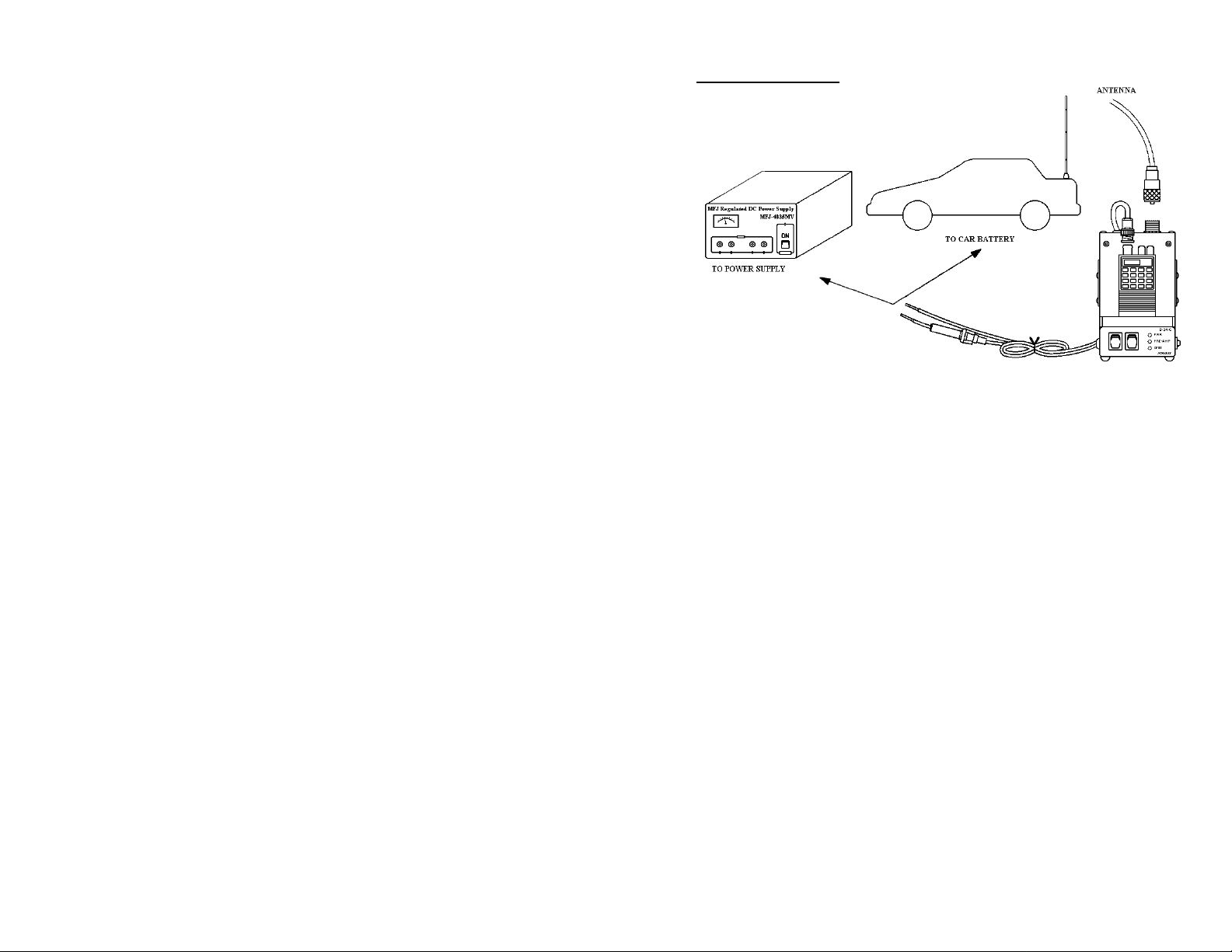
amplifier to the power supply is correct (a diagram is
shown on the following page.
8. The cord may be burned if the power supply is connected
in reverse polarity, especially if the power source is a
battery. Check the polarity well before connection. The
interior of this amplifier is protected from a reverse
polarity connection by a protection circuit.
-- -- 11
Page 13
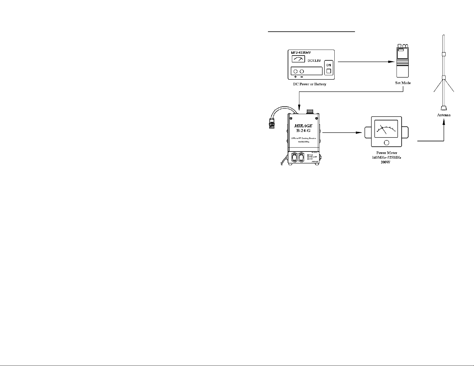
CONNECTION DIAGRAM
-- -- 12
Page 14
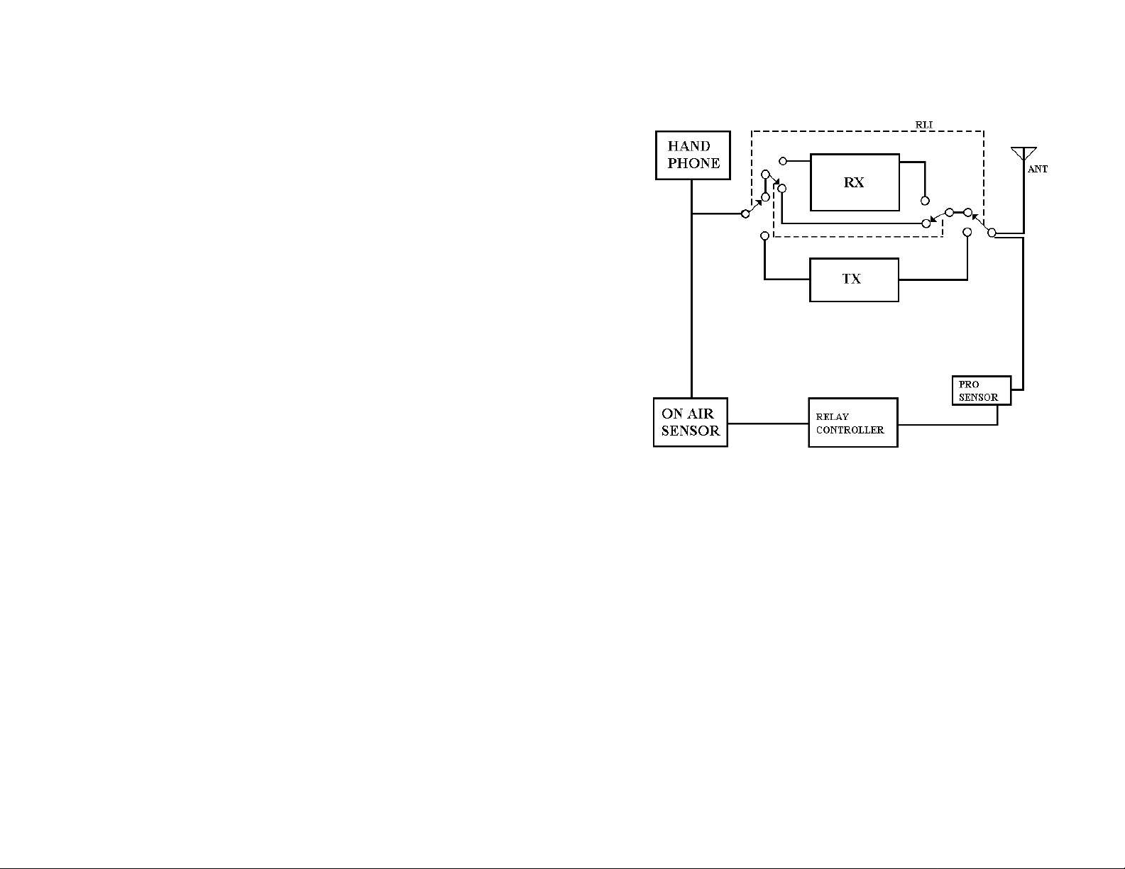
B-24-G BOOSTER AMP. BLOCK CIRCUIT
-- -- 13
Page 15

MIRAGE
Any Mirage Communications product found to be defective in materials or workmanship will be
repaired or replaced (at Mirage’s option) for a period of one year from the date of original
purchase.
During the warranty period Mirage Communications will provide, free of charge, both parts and
labor necessary to correct defects in material or workmanship.
•
To obtain such warranty service, the original purchaser must:
(1) Provide “proof of purchase”
(2) Ship the product in its original container or equivalent, fully insured and shipping
charges prepaid, to Mirage, as addressed below.
•
All internal adjustments are factory set for best performance consistent with reliable
operation. Changing internal adjustments may void this warranty.
•
Improper maintenance or repair may also void this one year warranty. We recommend that
units requiring repair during the warranty period be returned to the factory.
•
This unit was not designed for repeater operation, and its use in such service is at your own
risk.
•
Mirage assumes no responsibility for any item connected to or used in conjunction with this
product.
•
The foregoing constitutes Mirage’s entire obligation with respect to this product and the
original purchaser and any user or owner shall have no remedy and no claim for incidental
or consequential damages.
•
All Mirage products to be serviced, in-warranty or out-of-warranty, should be shipped,
freight paid to:
be accompanied by a letter describing the problem in detail. Be sure to include
NAME, ADDRESS, AND TELEPHONE NUMBER!
•
This warranty gives specific legal rights and you may also have other rights which vary
from state to state.
WARNING
radiation. The harmonic filters contained in the circuit will not suppress direct radiation that may
result if the cover is removed.
: This unit should not be operated with the cover removed . The cover confines RF
COMMUNICATION EQUIPMENT
300 Industrial Park Road
Starkville, MS 39759 USA
Tel: (601) 323-8287
FAX: (601) 323-6551
ONE YEAR LIMITED WARRANTY
Mirage, 921 Louisville Road, Starkville, MS 39759, USA
-- -- 14
. Product must
YOUR
 Loading...