

Page 1
MIRAGE KP-2 Pre-Amplifier
Instruction
Manual
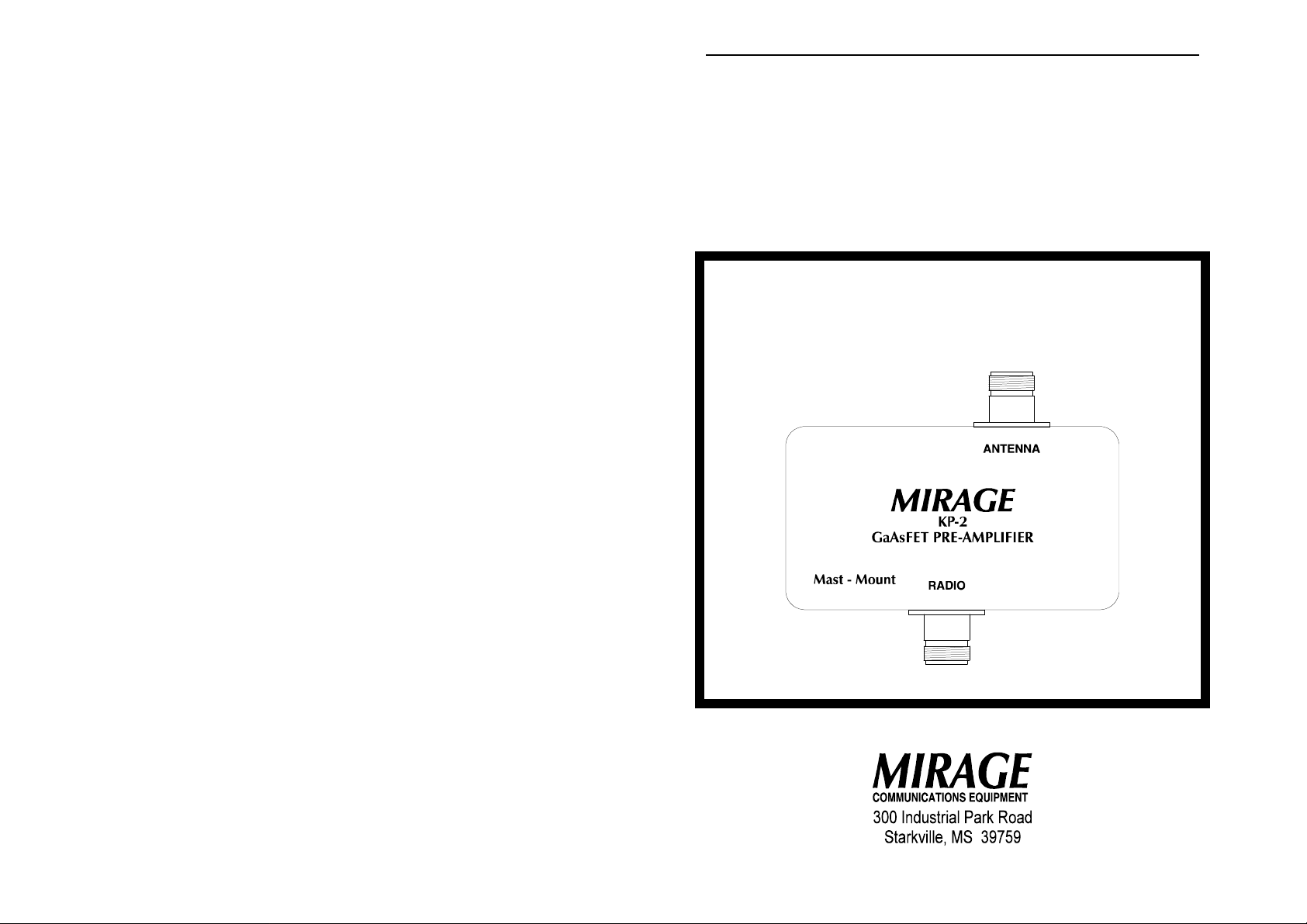
MAST-MOUNT GaAsFET PRE-AMPLIFIER
KP-2 Series
10M, 6M, 2M, 1-1/4M, 70 CM
Version A Copyright © 1996, MIRAGE Communications
Before operating this unit, please read these instructions completely.
1
Page 2

MIRAGE KP-2 Pre-Amplifier
MIRAGE KP-2 Mast-Mount Pre-Amplifier
General Information
This in-line GaAs-FET receive pre-amp provides high gain and low noise
amplification for weak receive signals. The KP-2 also has automatic RFswitching, which disengages the pre-amp any time it detects a
transmission signal being emitted by the tranceiver.
The KP-2 pre-amp has an attenuator built into the circuit which can be
selected by changing the position of a switch on the internal circuit board.
This switch is set in the LOW level gain position at the factory. This has
been included to prevent receiver overloading and subsequent
intermodulation distortion that can come from very strong signals.
The following is a list of associated parts shipped with the unit:
1 KP2RC Control Unit
1 1-3/4" U-Bolt
1 1-3/4" Cradle
2 5/16" Nuts with lock washers
KP2RC RF Line Voltage Control Unit
The RF line voltage control unit designated KP2RC requires that you
apply a positive 13.6 - 15 Vdc to the power jack positioned on the end of
the control box. The center pin is positive. When the KP2RC is turned
on, it places the DC voltage onto the RF signal line running up to the
antenna. The DC voltage is blocked at your radio by a coupling
capacitor. The mast-mounted KP-2 pre-amp is designed to pick this DC
voltage off the RF line and use it to power the pre-amp.
The RCA phono jack located on the side next to the RADIO connector
allows you to connect ON/OFF switching devices (such as an external
switch option on an SSB/CW radio) to the KP2RC. This option allows
you to automatically remove the DC voltage (by grounding the center pin
of the RCA phono jack) from the RF signal line any time your radio is in
the transmit mode.
2
Page 3

MIRAGE KP-2 Pre-Amplifier
Specifications
−−−− NOTE: Unless otherwise indicated, specifications apply to all
models of the KP-2 Series.
Frequency Coverage:
MIRAGE Model # Range
KP-2 / 10 Meter: 28.000 - 28.500 MHz
KP-2 / 6 Meter: 50 - 54 MHz
KP-2 / 2 Meter: 144 - 148 MHz
KP-2 / 1-1/4 Meter: 222 - 225 MHz
KP-2 / 70 Centimeter: 440 - 450 MHz
Gain: 20-25 dB (HIGH gain setting)
10-15 dB (LOW gain setting)
Noise Figure: 0.6 dB, independent of gain setting
Power Requirements: Positive 13.6 - 15 Vdc
Power Capability: 100 Watts, maximum
Connectors:
KP-2 Pre-Amplifier: 2 UG-58N VHF connectors
KP2RC Control Unit: 2 UG-58N VHF connectors
1 3.5mm Coax plug
1 RCA Phono plug
KP-2 Pre-Amplifier Installation
The MIRAGE KP-2 is designed to be easily mounted on your 1-3/4"
diameter antenna mast:
Place the supplied 1-3/4" U-bolt around your antenna mast and slip
1.
the supplied 1-34" cradle onto it.
2. Slip the base plate of the KP-2 (with the RADIO 'N'-connector
pointing down) onto the U-bolt.
Secure the KP-2 using the provided 5/16" nuts and lock washers.
3.
4. Connect the ANTENNA 'N'-connector of the KP-2 to your antenna
using RG-8U (or equivalent) cable.
Connect the coax from the Pre-Amp output of the KP2RC control
5.
unit to the RADIO 'N'-connector of the KP-2.
6. Ensure that ALL connections are tight!
3
Page 4

MIRAGE KP-2 Pre-Amplifier
KP2RC Control Unit Installation
This unit has been designed to allow operators to control the operation of
the mast-mounted KP-2 pre-amplifier by using the existing RF signal line
between the Ham Shack and the antenna to power the pre-amp. Locate
the Control Unit for ease of access to the ON/OFF switch.
From the ANTENNA side of the KP2RC Control Unit, run a length
1.
of good quality 50 Ohm coax cable from the 'N'-Connector to the
Antenna Mast. Allow enough length to reach the KP-2 PreAmplifier which will be mounted on your antenna mast.
Connect a positive 13.6 - 15 Vdc power supply to the 3.5mm DC
2.
coaxial power jack located on the end of the Control Unit. The
center should be positive with the sleeve ground.
++++
CAUTION: Before connecting the control unit to your
radio, ensure that there is no voltage on the
center-pin of the RADIO connector of the
KP2RC!
Connect a short length of good quality 50 Ohm coax cable from
3.
the ANTENNA output of your Radio to the 'N'-Connector on the
right side of the KP2RC Control Unit (the side with the RCA phono
connector).
MIRAGE KP-2 Pre-Amplifier and Control Unit
Figure 1
4
Page 5

MIRAGE KP-2 Pre-Amplifier
−−−− NOTE: If the KP2RC is turned OFF, there is no placement of DC
voltage on the RF signal line, and the pre-amp remains
inactive.
In cases of very weak signal reception, you may want to change the preamp gain level to the HIGH position. To do so, following these steps:
Remove the four screws in the cover.
1.
Carefully pry open the silicone-sealed cover.
2.
Move the two white toggles on the black switch (located
3.
approximately 1" from the RADIO connector) to the downward
position.
Reseal the cover with a small bead of silicone or other appropriate
4.
sealing material.
The MIRAGE KP-2 Pre-Amplifier is now ready to go! Apply power to the
KP-2 by placing the POWER switch on the KP2RC Control Unit in the ON
position. Power to the pre-amp is indicated by the LED located to the right
of the switch.
Technical Assistance
If you have any problem with this unit, first check the appropriate section
of this manual. If the manual does not reference your problem or your
problem is not solved by reading the manual you may call MIRAGE at
601-323-8287. You will be best helped if you have your unit, manual and
all information on your station handy so you can answer any questions
the technicians may ask.
You can also send questions by FAX to 601-323-6551. Send a complete
description of your problem, an explanation of exactly how you are using
your unit, and a complete description of your station.
5
 Loading...