

Page 1

Instructions for installing the API CMS-1
The API CMS-1 includes:
2 Bezels with Templates
2 Grilles
4 Long Metal Channels
4 Short Metal Channels
4 Z Brackets
40 Drywall Screws (4 extra)
14 Rubber Cups (2 extra)
8 Wall Anchors
18 Machine Screws (2 extra)
Tools required:
Drywall Cutting Tool
Drill
3/16"(5mm) Drill Bit
Phillips Screwdriver
Hammer
Versatility
Whether integrated into simple drywall or with studs of
any spacing, the proprietary design of the new API CMS-1
provides a sturdy, unyielding custom speaker installation
for any retrofit construction application.
Avoid installing the speaker in front of anything that may
impede its insertion to the wall such as ducts, pipes, or
studs. The use of a stud finder should guarantee a
suitable location.
Step 1: Installing the Bezel
In the desired location, squarely position the bezel upright
so the wording on the template can be read. If an
electrician has already passed the speaker to this area,
pull the exposed wire through the hole in the middle of the
template marked "Speaker Wire". The in-wall kit and
matching speakers can be positioned in a variety of ways
but this is the suggested manner to maximize dispersion.
For ceiling applications, position the bezel so the longer
sides face the side walls.
Drill a guide hole into the wall through each of the four
corner protruding cylinders of the bezel using a 3/16”
drill bit. Remove the bezel. With a hammer, gently tap a
wall anchor into each of the 4 drilled holes. Attach the
bezel to the wall using four of the provided drywall screws
inserted through the four protruding corner cylinders and
into the drywall anchors. Tighten the screws securely, to
the point of good resistance, but be careful not to overtighten. This step is cosmetic, not structural; the bezel
will be further solidified in proceeding steps. The bezel is
now in place and can be painted.
Step 2: Making the Cuts
Insert a drywall-cutting tool into the 1.5” by 5”
rectangular slot in the template under the API logo and
cut out this area. This provides a useful handle to the
drywall for ease of cutting the next piece and prevents it,
and the speaker wire, from falling into the wall.
Next, insert a drywall-cutting tool into the guide cut
passage between the template and bezel. Cut out this
square, leaving just the bezel, speaker wire, and the open
hole where the speaker will be housed. Cut as flush to the
bezel border as possible to result in a smooth fit for the
metal channels and speaker. If necessary, lightly sand the
edges of the drywall to remove any rough spots. This
provides a smooth surface to allow a flush fit for the
metal channel.
Page 2
Step 3: Installing the Metal Channels
Now the opening is ready to be reinforced with the metal
channels. Each channel has a distinct front and back.
The front is identifiable by larger perforations on the front
portion that slides between the bezel and drywall. The
back is identifiable by the smaller perforations and a flared
bend that allows it to be pliable and opened to
accommodate thicker drywall. The front portion of each
channel will slide between the drywall and bezel; the rear
portion grips the back of the drywall. The perforations
allow the drywall screws easy passage through the
channel. Slide the longer metal channels on the vertical
sides of the opening, the shorter channels on the top and
bottom. If necessary, lightly tap the channels into place
with a hammer to move them as flush as possible to the
drywall.
If a border of the hole happens to be flush to a stud,
it will not allow nor need the application of the metal
channel. The stud will provide all the needed foundation
for the drywall screw to grip and provide a sturdy,
reliable installation.
There are 3 holes located on the top and bottom of the
bezel. Keep the channels flush to the drywall and attach
the bezel to the wall through the pre set holes with
drywall screws. Tighten the screws securely, to the point
of good resistance, but be careful not to over-tighten.
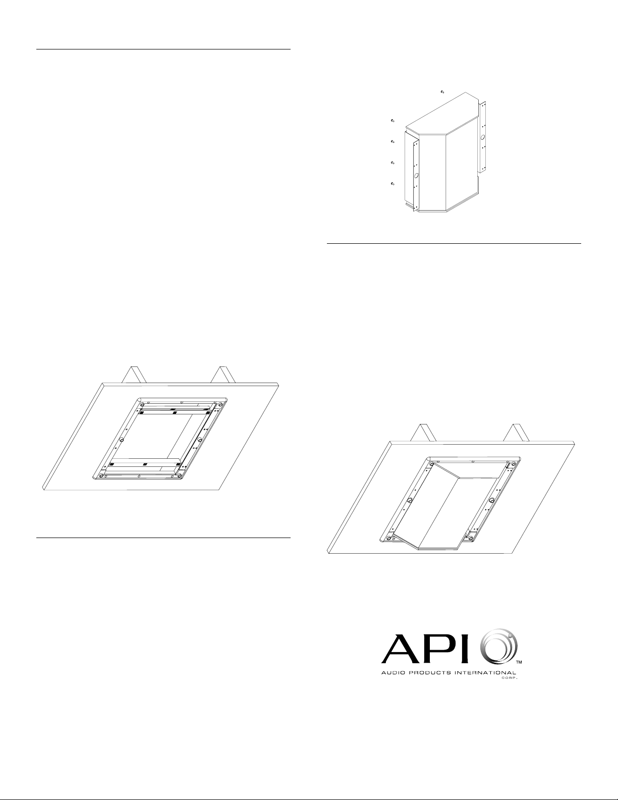
Step 4: Attaching the Z Brackets
The provided Z brackets form the attachment between
the speaker and the in wall bracket.
For Incognita HDT-R installations:
First, remove the 8 screws that hold the Incognita HDT-R
grille to the speaker. Remove the grille.
For Energy Veritas 2.0r:
First, remove the grille. Do not attach the side trims
to the Veritas 2.0r. If they have been attached,
remove them.
For both the Incognita HDT-R and Veritas 2.0r:
The back of the speaker has 8 vertical machine screw
inserts, 4 on each side. The Z brackets' rear portion has
4 predrilled holes positioned to match these screw
inserts. Position the Z bracket so this edge matches
these holes. The front portion of the Z bracket has 4 sets
of two vertical holes and a centered, larger hole.
This portion faces forward, towards the front of the
speaker. Attach the Z bracket with the 4 screws that
were removed from the back of the speaker. Follow this
procedure for both the left and right sides of the speaker.
Step 5: Inserting the Speaker
The speaker can now slide into the pre-cut opening with
the attached Z brackets fitting into the bezel and over the
cylinders located at the middle. If the installation does not
use studs, use the set of 4 vertical screw holes closest to
the speaker. If the installation did not require the metal
channels and uses studs, use the set of 4 vertical screws
holes furthest from the speakers. Attach each side Z
bracket to the bezel with 4 of the provided drywall screws
into the selected set of pre-drilled holes. Tighten the
screws securely, to the point of good resistance, but be
careful not to over-tighten.
Insert the 6 rubber cups into the six protruding cylinders.
Finally, with clean hands, attach the grille into these
cylinders.
Audio Products International Corp.
3641 McNicoll Avenue, Scarborough
Ontario, Canada M1X 1G5
416-321-1800 Fax 416-321-1500
Printed in Canada Part #
 Loading...