

Page 1
Direct Vent Insert
INSTALLATION
AND
OPERATING
INSTRUCTIONS
SERIES A
DIRECT VENT
FIREPLACE INSERT
f i r e - p a r t s . c o m
WARNING: If the information in this manual is not followed exactly, a fire or
explosion may result causing property damage, personal injury or loss of life.
-- Do not store or use gasoline or other flammable vapors and liquids in the
vicinity of this or any other appliance.
-- WHAT TO DO IF YOU SMELL GAS
- Do not try to light any appliance.
- Do not touch any electrical switch; do not use any phone in your building.
- Immediately call your gas supplier from a neighbour’s phone. Follow the
gas supplier’s instructions.
- If you cannot reach your gas supplier, call the fire department.
--Installation and service must be performed by a qualified installer, service
agency or the gas supplier.
IMPORTANT: THESE INSTRUCTIONS ARE TO REMAIN WITH THE HOMEOWNER
200598-24 DVI-INST # 5055.65
Page 2
Contents
Caution....................................................................................... 3
Safety ......................................................................................... 3
Maintenance............................................................................... 3
Installation ................................................................................. 4
Clearances.................................................................................. 5
Venting ...................................................................................... 6
Rocker Switch............................................................................ 7
Gas Supply................................................................................. 8
Burner Assembly ....................................................................... 8
Brick Panels Installation.......................................................... 10
Levelling Legs ......................................................................... 10
Log Set..................................................................................... 11
Surround Assembly ................................................................. 12
First Fire................................................................................... 13
f i r e - p a r t s . c o m
Operation ................................................................................. 13
Primary Air Adjustment .......................................................... 13
Optional Blower ...................................................................... 15
Replacement Parts ................................................................... 16
Glass Frame Removal.............................................................. 18
Optional Radiant Overlay........................................................ 18
Appendix A.............................................................................. 19
Vent Terminal Kit .............................................................. 19
Vent Terminal Flashing Installation Guide ....................... 20
Optional Blower Kit ........................................................... 21
Louver Kit Installation Guide ............................................ 22
Safety Label........................................................................ 23
2
Page 3
Caution
Maintenance
FOR YOUR SAFETY - Do not install or operate your Pacific
Energy Mirage Direct Vent Gas Insert without first reading
and understanding this manual. Any installation or operational deviation from the following instructions voids the
Pacific Energy Gas Stove Warranty and may prove hazardous.
This appliance and its individual shutoff valve must be
disconnected from gas supply piping system during any
pressure testing of that system at test pressures in excess of 1/
2 psig. (3.5 kPa)
This appliance must be isolated from the gas supply piping
system by closing its individual manual shutoff valve during
any pressure testing of the gas supply piping system at test
pressures equal to or less than 1/2 psig. (3.5 kPa)
Note: When lit for the first time, the appliance will emit a
slight odour for a couple of hours. This is due to the curing
of paints, sealants and lubricants used in the manufacturing
process. This condition is temporary. Open doors and
windows to ventilate area. Smoke and fumes caused by the
curing process may cause discomfort to some individuals.
f i r e - p a r t s . c o m
Safety
Due to high temperatures, this gas appliance should be
located out of traffic and away from furniture and
draperies.
Children and adults should be alerted to the hazards of
high surface temperature and should stay away to avoid
burns or clothing ignition.
Young children should be carefully supervised when they
are in the same room as the appliance.
Clothing or other flammable material should not be placed
on or near the appliance.
Any grill, panel or door removed for servicing the unit
must be replaced prior to operating. Failure to do so may
create a hazardous condition.
Installation and repair should be done by a qualified
service person. The appliance should be inspected before
use and at least annually by a professional service person.
More frequent cleaning may be required due to excessive
lint from carpeting, bedding material, etc. It is imperative
that control compartments, burners and circulating air
passageways of the appliance be kept clean.
Caution: Turn off gas and electrical power supply and allow
ample time for unit to cool before servicing appliance. It is
recommended that this appliance and venting should be
inspected at least once a year by a qualified service person.
Do not use this heater if any part has been under water.
Immediately call a qualified service technician to inspect the
heater and to replace any part of the control system and any
gas control which has been under water.
Annual Inspection:
a) Clean louvers and air passage ways of excessive lint
buildup from carpeting, bedding material, etc. The flow of
combustion and ventilation air must not be obstructed.
b) Remove glass panel and log set. Inspect logs and burner
assembly for lint and soot buildup. If excessive buildup of
soot is present, have a qualified service person inspect and
adjust unit for proper combustion. Clean logs and burner with
a vacuum cleaner, paying close attention to burner ports.
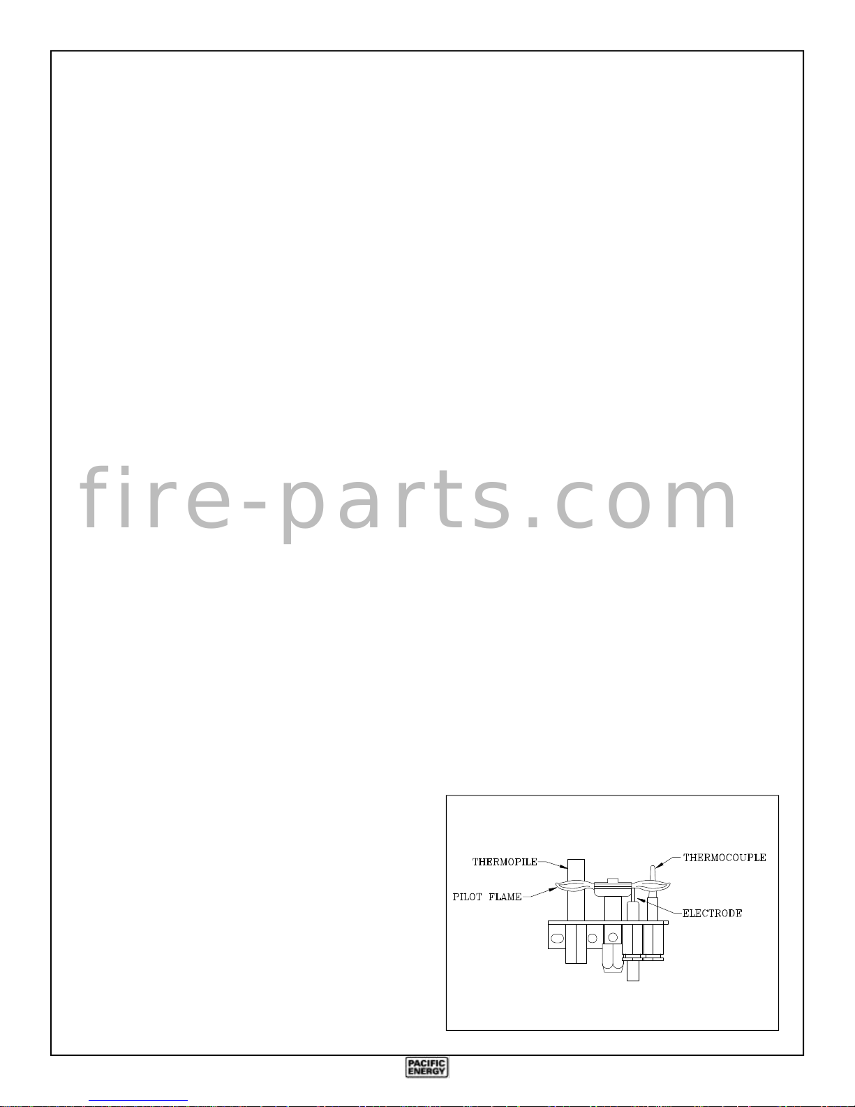
c) Check the pilot system for proper operation. (See Fig.
#1)
d) Check that the chimney flue and its outlet are open and
free from blockage or debris.
e) Check glass panel gasket, replace if necessary.
Note: The appliance area must be kept clear and free from
combustible materials, gasoline and other flammable vapours and liquids.
Periodically:
a) Viewing glass may be cleaned with glass cleaner.
b) Exterior porcelain enamel finish may be cleaned with
soap and water.
Note: Never use abrasives to clean this appliance.
Fig. # 1
It is Pacific Energy’s policy that no responsibility is
assumed by the Company or by any of its employees or
representatives for any damages caused by an inoperable,
inadequate, or unsafe condition which is the result, either
directly or indirectly, of any improper operation or
installation procedures.
3
Page 4
Installation
The Mirage Direct Vent Gas Insert installation and venting
must conform to the current CAN/CGA-B149 installation
code (in Canada) or the National Fuel Gas Code, ANSI
Z223.1 -1988 (in the USA), and approved per local codes.
Only qualified (licensed or trained) personnel should
install this product.
Fig. # 3
Existing Fireplace
(Masonry or Factory Built)
The Mirage Direct Vent Gas Insert is designed to be installed
into a masonry or a factory built zero clearance fireplace. The
masonry fireplace must be built according to the requirements of the standards for chimneys, fireplaces, vents and
solid fuel burning appliances, NFPA 211 (Latest Edition) or
applicable National, Provincial, State or local codes. The
factory built zero clearance fireplace and its chimney must be
certified and meet applicable National, Provincial, State or
local codes.
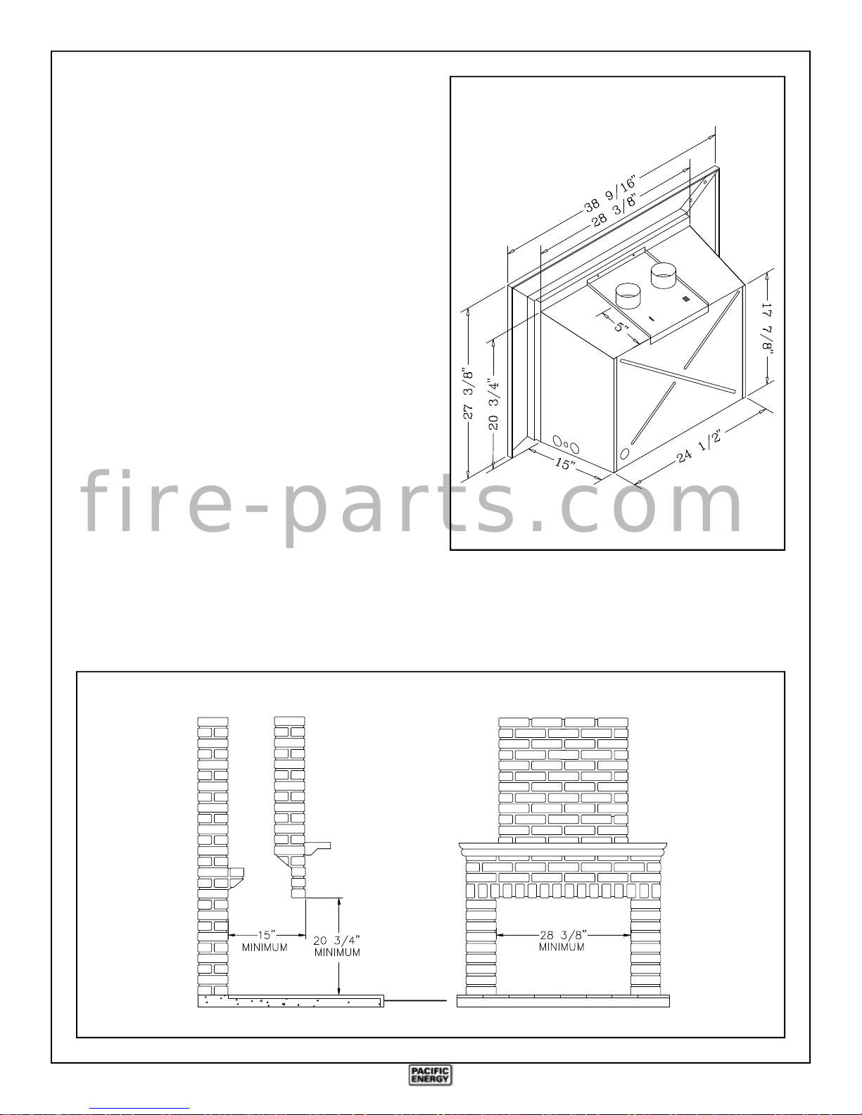
In order to sufficiently accommodate the Mirage Direct Vent
Gas Insert, the minimum size of the fireplace should be 28-3/
f i r e - p a r t s . c o m
8 inches wide, 20-3/4 inches high and 15 inches deep (see
Fig.#2).
The fireplace and its chimney should be swept and inspected.
The existing fireplace damper (if present) should be locked
open or removed completely if the opening is too small for
two - 3" flue liners to pass through.
Fig. # 2
4
Page 5
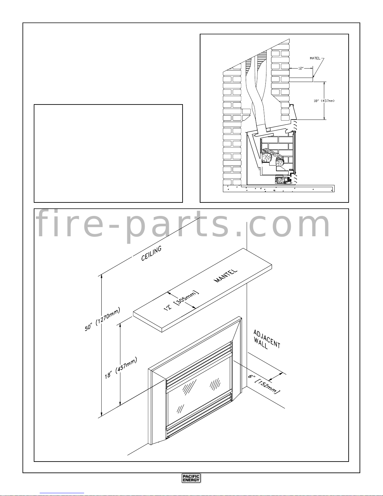
Clearances
The minimum clearances from the appliance to combustible
surfaces are shown on Fig. #4 and #5. Adequate clearances
around air openings and combustion air supplies are required.
MINIMUM CLEARANCES
TO COMBUSTIBLES:
Adjacent sidewall: .......................6.0 in. (152 mm)
Ceiling to appliance:.....................50 in. (1270 mm)
Mantel to appliance:.....................18 in. (457 mm)
Maximum mantel extension: .......12 in. (305 mm)
Mantel top support
to appliance ...................................18 in. (457 mm)
Mantel side support
to appliance .....................................6 in. (150 mm)
Fig. # 4
Fig. # 5
f i r e - p a r t s . c o m
5
Page 6
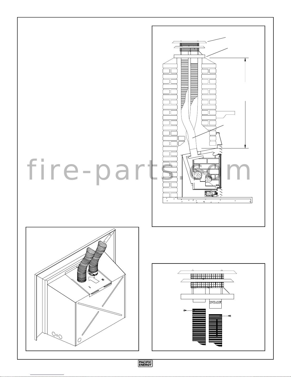
Venting
Fig # 7
Vent Terminal
Caution: Only Flex Liner kit (MIND.FL25) or an approved
gas vent flue liner and a Vent Terminal (MIND.VTTERM)
is approved for use with this appliance.
Also approved for use is Simpson Dura-Vent GS
termination kits, both Standard Vertical Termination cap
(#980) and the Extended Vertical Termination cap (#930)
in conjunction with the 3" Co-Linear Termination kit
(#923GK).
No other venting system or components may be used.
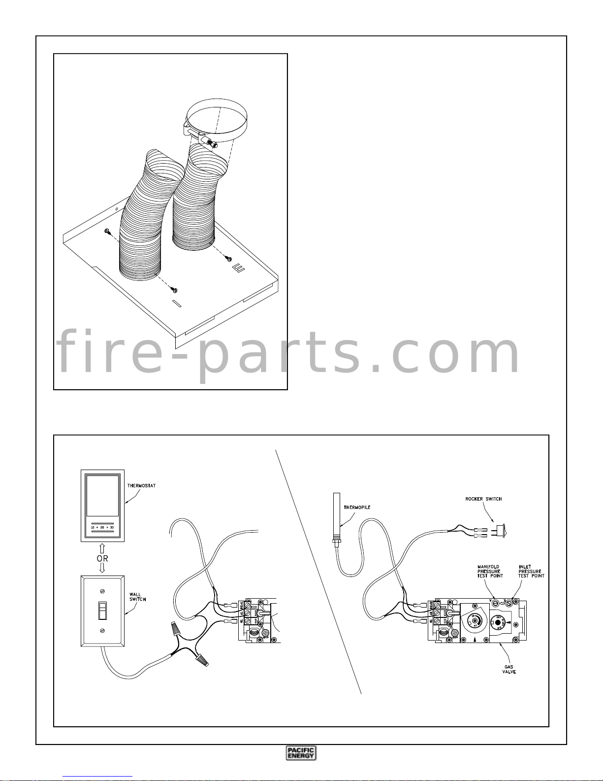
1) Measure chimney height and cut flex liner as required.
Mark one of the pipes with a stripe to identify combustion
air intake pipe from flue outlet pipe.
2) Attach marked flex liner pipe to the intake side (longer
collar) of vent terminal. Seal and secure with sealant and
screws provided. Attach the other pipe to the outlet side
of vent terminal. Seal and secure with sealant and screws
provided.
3) Insert both flex liners from top of the chimney, down
through the damper opening.
4) The vent terminal is sized to fit most typical chimneys.
Before attaching vent terminal to top of chimney, apply a
bead of caulking to top of clay liner. Slip vent terminal
over liner and secure in place with lateral retaining bolts.
f i r e - p a r t s . c o m
5) For larger chimneys, an optional flashing is available
which may be cut and fitted to suit. The flashing attaches
to the underside of the terminal with four nuts provided.
Caulk the flashing in place to seal any gaps.
Seal
Min. ........ 8' (2.4m)
Max. .......36' (10.9m)
3" Flex
Liner
The vent terminal must be sealed in place to prevent water
from entering the existing chimney.
Fig # 6
Note: The vent must be a minimum 8' long and
must not exceed a total lenght of 36'.
6) Remove the screw located above the top louver which
retains the vent connector plate on the appliance. Attach
ends of the flex liners to the collars on top of the connector
plate.
Fig # 8
6
Page 7
Make sure the marked inlet pipe is attached to the inlet side
Fig # 9
(marked "I"), and the unmarked pipe is attached to the
outlet side (marked "E") of the connector plate.
7) Seal and secure inlet pipe with sealant and screws provided.
8) Slip the 3 1/2" pipe clamp loosely over the end of the flex
flue pipe. Slide the pipe over the collar (marked "E") of
the vent connector plate and clamp tightly in place.
Secure in place with screws provided. No additional seal
is required.
9) Position vent connector plate over top of unit as the Insert
is pushed into the fireplace. Clip connector plate at the
back of the unit, tip down into position and attach in place
with screw previously removed. Leave the Insert extending a couple of inches out of the fireplace temporarily to
allow for proper surround placement.
Rocker Switch
No electrical connection is required for the gas system operation. The self generating pilot provides current for the
optional remote wall switch.
The installation of a wall switch allows for manual remote
operation of fireplace, and automatic operation with a wall
f i r e - p a r t s . c o m
thermostat. Use a switch or thermostat rated for millivolts.
Position the wall switch or thermostat so that a maximum of
25 feet of wiring from the switch to the fireplace is used. Use
18/2 thermostat wire. Connect the wall switch to the valve as
shown in Fig. #10.
Fig # 10
Optional Wall Switch or Thermostat
Rocker Switch
7
Page 8
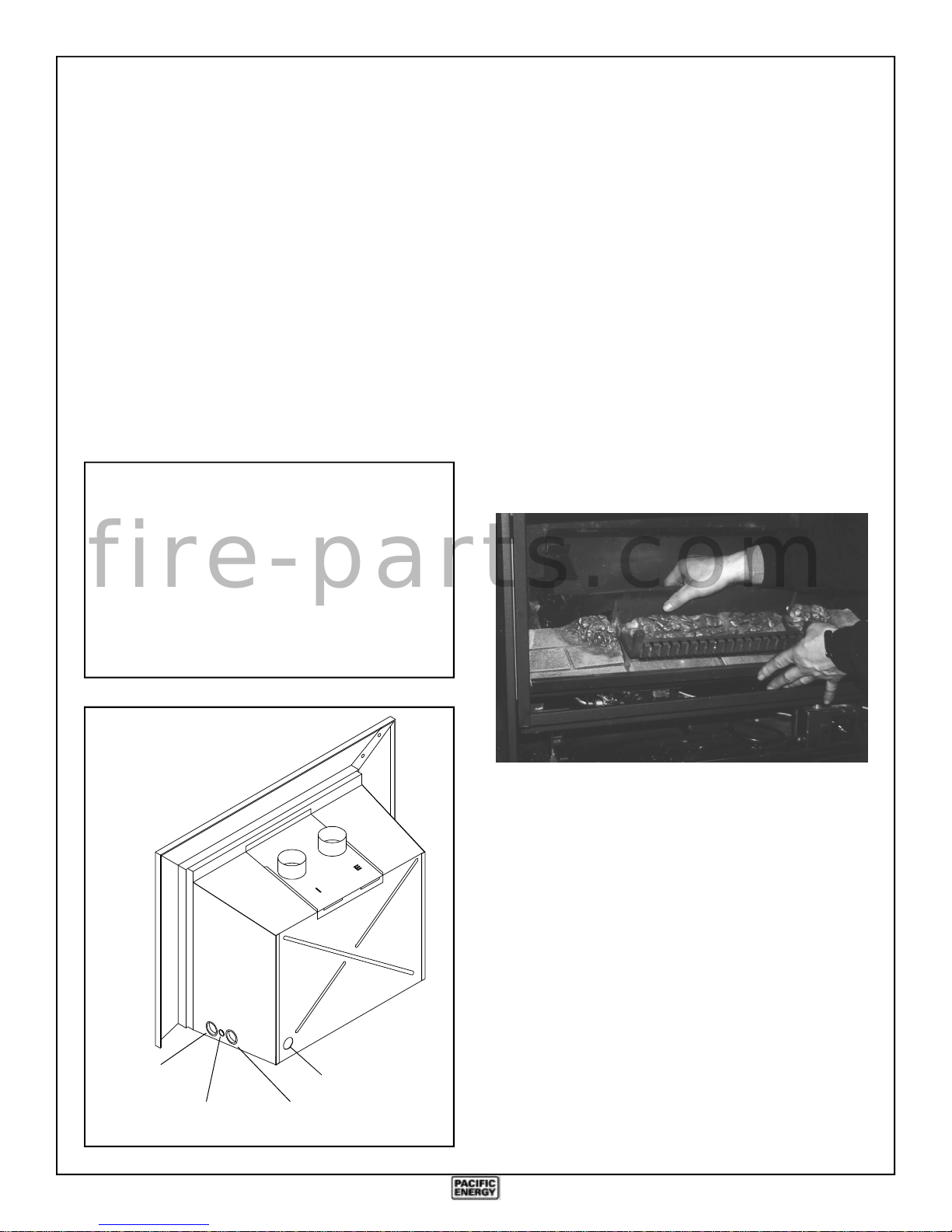
Gas Supply
Burner Assembly
Caution: The gas line should be installed by a qualified
service person in accordance with all building codes. Consult
local and/or national building codes before altering the fireplace.
The Mirage Direct Vent Gas Insert comes equipped with a
flexible connector with a 3/8" N.P.T. Male inlet for easy gas
connection. This connector is attached to the control valve
under the burner assembly and may exit the gas Insert at the
bottom left front or left rear. (Fig. #11)
Proper gas line diameter must be used to assure proper
operation. A pressure test port (1/8 inch N.P.T. plugged
tapping) must be provided for checking gas pressure. This
port must be located immediately upstream of the gas supply
connection to the appliance.
Correct gas pressure requirement:
Natural Gas Propane
Min. Pressure 5.0" wc 11.0" wc
(For purpose of input adjustment)
f i r e - p a r t s . c o m
Max. Pressure 10.5" wc 13.0" wc
The glass frame must be removed to install the burner into the
firebox. The glass frame is held in place by two over-center
latches located under the firebox.
1) Fold down the bottom louver, if installed, to access the
over-center latch. Disengage the latches by pulling each
lever down and forward.
2) Grasp the sides of the frame and swing the bottom out to
clear. Lift it up and forward to disengage from the top and
place in a safe place to avoid damage.
3) Remove the wrapped logs and brick panels and set aside,
taking care not to damage them.
4) Remove burner assembly from the carton and inspect.
Remove the two wing nuts contained in the plastic bag in
the carton.
Manifold Pressure 3.8" wc 11.0" wc
Fig # 11
Optional Blower
Cord Exit
Wire Harness
Gas Inlet
Exit
Rear Knockout
5) Bend the flexible inlet connector so that the line extends
straight from the control valve. While placing the burner
into the firebox, feed the flex gas inlet pipe through the
front plastic bushing located in the casing side. The flex
inlet pipe should extend out of the casing side, through the
plastic bushing.
A knockout is provided at the right rear of the appliance as an
alternate exit for the flexible connector. To use this inlet,
remove the knockout from the rear of the appliance. (Fig.
#11) Remove the plastic bushing installed in the side and
reinstall into the hole at the rear of the appliance.
6) Angle the burner assembly slightly forward, and place
inside the firebox. Be sure to align the two studs on the
side of the burner with the holes provided in the firebox
bottom side ledges. (Fig. #12)
8
Page 9

7) Once positioned inside the firebox and
properly seated on the ledge, push the
burner assembly back and secure in
place with wing nuts provided. (Fig.
#12)
8) Fasten rear burner bracket to firebox
back with screws provided. (Fig. # 13)
9) Connect the wire harness from the
rocker switch to the control valve terminal marked "TH" and "TH TP".
(Fig. #12) Feed the wire through the
smaller plastic bushing located next to
the gas inlet hole in the side casing.
(Fig. #11)
10)Place the self-adhesive label into the
blank box provided on the rating label
to designate the type of gas the appliance is connected to.
Fig # 13
f i r e - p a r t s . c o m
Fig # 12
Wing Nut
9
Page 10

Brick Panels Installation
Levelling Legs
The panels for the firebox are shipped in a separate cardboard
box located inside the appliance. Carefully remove the panels
from the box and install them as follows:
1) Insert the right side panel into the firebox. Push the panel
completely to the rear so that it clears the window frame,
and then bring it forward slightly so that it tucks in behind
the window frame and allows room for the thickness of the
rear panel to come behind it.
2) Install the rear panel by tipping it back and into the space
between the baffle and the back of the firebox and so that
it sits on the ledge provided. Shift the rear panel temporarily to the right so that it tucks in behind the right side
panel, leaving room for the left panel to pass by it.
3) Similarly to installing the right panel, push the left panel
all the way to the rear to clear the window frame and then
pull it forward so that it tucks in behind the window frame.
4) Center the rear panel and then adjust the side panels by
pushing them back against the rear panel.
Levelling legs are provided with the appliance as a convenient means for levelling the appliance when it is installed on
an irregular surface. The legs (3" long threaded bolts) are
supplied in a separate parts bag inside the appliance. Nuts
welded to the base, near the back of the appliance locate the
levelling legs. The legs thread into the nuts and protrude out
the bottom, raising the rear of the appliance until it is level
with the front.
f i r e - p a r t s . c o m
Fig # 14
10
Page 11

Log Set
The Ceramic logs are durable and long lasting when installed
properly. However, they are delicate and may be damaged
easily if not handled with care. Unpack and inspect log set.
There should be a total of 4 logs as shown in Fig. # 16. All gas
and venting connections should be made before installing log
set.
Log Assembly: (Fig. # 15)
Fig. #16
Back Log
1) Place the rear log in position at the back of the firebox,
centered between the brackets, with flat side facing rear
and the bark side facing forward.
2) Place the front log over the two pins just in front of the rear
burner onto the tabs located at the front of burner
assembly. The log is notched to fit over the pilot.
3) The top left "Y" log bridges across front and rear log. The
log should be properly seated over pin in the front log and
nested in the left relief of the rear log.
4) The top right log also bridges across the front and rear log.
The log should be properly seated over the pin in the front
log and nested in the right relief of the rear log.
Note: Improper placement of logs may cause sooting on
internal parts and glass.
f i r e - p a r t s . c o m
Fig # 15
Left "Y" Log
Back Log
Front Log
Top Left "Y" Log
Top Right Log
Right Log
Front
Log
11
Page 12

Surround Assembly
1) Lay Parts A, B, and C face down on a flat, non-marking
surface. (Fig. #17) Fasten together with spring clips
through holes at points "D". (Fig. #20)
2) Lift the surround assembly to the upright position and
make sure the front face is even at the joint.
3) Assemble the three brass trim pieces using the enclosed
hardware. Slide Part F into the back corners of the brass
trim and tighten screws. Ensure the mitred corners fit
tightly and evenly. (Fig. # 18)
4) Slide the assembled brass trim over the surround from the
top. (Fig. # 17)
5) Tighten the retaining screws at the bottom of each brass
trim side. (Fig. # 21)
Fig. # 17
Fig. # 18
6) Connect the wire from the gas control valve to the on/off
rocker switch in the brass trim. (Fig. # 19)
7) Slide pre-assembled surround on to Insert. Do not lift the
assembly by grasping the brass trim. The surround is
held in place by screws (2 each side), just inside the casing
near the top and bottom. Push surround back until snug
and even with front face of Insert. Fasten in place.
Fig. # 20
Fig. # 19
f i r e - p a r t s . c o m
8) Push the entire appliance back until the surround is in
contact with the fireplace.
Fig. # 21
12
Page 13

First Fire
Primary Air Adjustment
When lit for the first time, the appliance will emit a slight
odour for a couple of hours. This is due to the curing of paints,
sealants and lubricants used in the manufacturing process.
This condition is temporary. Open doors and windows to
ventilate area. Smoke and fumes caused by the curing process
may cause discomfort to some individuals.
Operation
The Mirage Gas Insert comes equipped with an "ON-OFF"
Rocker switch. This switch is conveniently located near the
upper right hand corner of the surround
Once a pilot light has been established, and the gas control
knob turned to the "ON" position, the burner may be turned
on or off simply with the switch. An optional wall thermostat
may be installed to operate the burner automatically.
Fig. # 22
This appliance is provided with primary air adjustment,
which affects flame heights and flame quality of the front and
back burners by controlling the air shutter opening. This
adjustment is preset at the factory for the best flame appearance for most installations. However, adjustment is available
to compensate for varying field conditions, such as vent
system height or altitude, that may affect flame appearance.
The adjustment rods are accessible just to the left of the valve,
in behind the bottom louver, as shown in Fig. #23. Separate
front and back adjusters are provided; the left rod adjusts the
rear burner and the right adjuster controls the front burner.
Pulling the left rod forward closes the rear shutter and
increases the rear flame height. Pushing the right rod upwards
closes the front shutter and increases flame height of the front
burner.
Fig. # 23
f i r e - p a r t s . c o m
Manual HI-LO Burner Control Knob
Manual HI-LO Flame Adjustment: (Fig #22)
The HI-LO burner control knob can be rotated in both
directions, providing infinite control of gas flow rate to the
burner and therefore greater comfort control. The HI setting
provides a maximum gas input, and rotating the knob clockwise toward the LO setting will reduce the gas input to a
minimum setting.
Wall Thermostat (optional):
Set the wall thermostat to a comfortable temperature. Turn
the HI-LO burner control knob to a desired setting. As heat
is required, the Mirage Gas Insert will turn on or off automatically, as needed.
Extend Shutdown:
To shutdown the appliance including the pilot, partially
depress and turn gas control knob clockwise past “PILOT” to
the “OFF” position. DO NOT FORCE.
NOTE: The SIT control has an interlock device which does
not allow the pilot to be lit when the appliance is at operating
temperature. Let the appliance cool down (approx. 60 sec.)
before attempting to relight the pilot. DO NOT use force to
rotate the control knob.
To Adjust: (See Fig. # 23)
1) Fold down bottom front louver.
2) Pull or push on adjustment rods to adjust flame.
3) Close bottom front louver.
Caution: Proper air shutter setting is a must. The flame
should not impinge on the top of the firebox. It should
NEVER be set to create sooting on internal parts and glass.
Open air shutter gradually until sooting stops.
Fig. # 24
13
Page 14

FOR YOUR SAFETY READ BEFORE LIGHTING
WARNING: If you do not follow these
instructions exactly, a fire or explosion
may result causing property damage,
personal injury or loss of life.
A. This appliance has a pilot which must be lighted by
hand. When lighting the pilot, follow these instructions exactly.
B. BEFORE LIGHTING smell all around the appliance
area for gas. Be sure to smell next to the floor
because some gas is heavier than air and will
settle on the floor.
WHAT TO DO IF YOU SMELL GAS:
- Do not try to light any appliance.
- Do not touch any electric switch; do not use any
phone in your building.
- Immediately call your gas supplier from a neighbour's phone. Follow the gas supplier's instructions.
- If you cannot reach your gas supplier, call the fire
department.
C. Use only your hand to push in or turn the gas control
knob. Never use tools. If the knob will not push in
or turn by hand, don't try to repair it, call a qualified
service technician. Force or attempted repair may
result in a fire or explosion.
D. Do not use this appliance if any part has been under
water. Immediately call a qualified service technician to inspect the appliance & to replace any part
of the control system & any gas control which has
been under water.
LIGHTING INSTRUCTIONS
1. STOP! Read the safety information above on
this label.
2. Set wall thermostat to lowest setting, if applicable.
3. Turn off all electric power to the appliance.
4. Open the bottom grill to access the controls.
5. Partially depress and turn gas control knob
clockwise past "Pilot" to "Off" position.
Note: Knob cannot be turned
from "Pilot" to "Off" unless
knob is pushed in slightly.
Do not force.
6. Allow sufficient length of
f i r e - p a r t s . c o m
time (minimum 5 minutes)
for any gas in the combustion chamber to
escape. If you still smell gas, STOP! Follow "B"
in the safety information above on this label. If
you don't smell gas, go to the next step.
7. Turn gas control knob back to "Pilot" position.
8. Depress gas control knob fully and hold while
GAS KNOB
you ignite pilot with the push button igniter. Once
the pilot ignites, continue depressing knob for
approximately 5 seconds (30 seconds if equipped
with a Robertshaw control valve). If pilot does not
stay lit, repeat steps 6 through 8, allowing a
longer period before releasing gas control dial.
- If gas control knob does not pop up when
released, stop and immediately call your service
technician or gas supplier.
- If the pilot will not stay lit after several tries, turn
the gas control knob to "Off" and call your
service technician or gas supplier.
9. Turn gas control knob counter-clockwise to
"On" position.
10. Turn HI-LO burner control knob to desired
setting.
11. Close bottom grill and turn on the burner switch
12. Turn on all electric power to the appliance.
13. Set thermostat to desired setting, if applicable.
Note: Sufficient time must be allowed for air to
escape from lines if the unit is being lit for the
first time.
TO TURN OFF GAS TO APPLIANCE
1. Set wall thermostat to lowest setting, if applicable.
2. Turn off all electric power to the appliance if
service is to be performed.
3. Push in gas control knob slightly and turn
clockwise to "Off". Do not force.
14
Page 15

Optional Blower
Electrical Supply:
Circulating air blower electrical rating: 115V, 60
Hz, 80 watts. (Fig #25) For your protection against
shock hazard, use only a properly grounded outlet
that will accept a three-pronged plug. Do not cut or
remove the grounding prong.
Consult local codes or, in the absence of local
codes, with the current CSA C22.1 Canadian Electrical Code and in the USA with the National
Electrical Code, ANSI/NFPA 70 (latest Edition).
Installation:
The blower kit must be installed before the burner
assembly is in place. Unpack and inspect blower
kit.
1) Position the blower onto studs located at the
rear of the appliance and secure in place with
wing nuts provided. (Fig. #26)
2) Place the speed control junction box temporarily in the right front corner of the appliance. The
junction box attaches to the underside of the
burner assembly, once in place. (Fig. #27)
3) Feed the power cord out through the plastic
grommet on the side of the appliance.
f i r e - p a r t s . c o m
Fig. # 26
Fig. # 27
Optional Blower
Studs
Fig. # 25
Rocker
Switch
Speed
Control
Snap Disc
Switch
115 Volts
60 Hz
0.5 Amperes
Blower
G (green)
L1 (white)
L2 (black)
Operation:
The circulating air blower is thermostatically controlled to
turn on automatically once the unit is at operating temperature. A few minutes after the appliance is lit, with the variable
speed control set at a desired setting, the blower will automatically turn on. The blower will automatically turn off a
few minutes after the appliance is shut down.
The blower may also be operated manually. Push the rocker
switch to manual position and the blower will operate independent of the burner provided the variable speed control is
set.
15
Page 16

Replacement Parts
Fig. # 28
(WHEN ORDERING, INCLUDE PART NUMBER WITH DESCRIPTION)
ITEM DESCRIPTION PART NO. ITEM DESCRIPTION PART NO.
1 .......... Main Body....................................... MIND.1800
2 .......... Baffle ............................................... MIND.1834
3 .......... Burner Assembly .....................MIND.NAT/PRO
4 .......... Glass Panel .....................................MINC.50342
5 .......... Glass Frame ..................................... MIND.1820
6 .......... Front Trim Set (2 pcs.) .................... MIND.1888
7 .......... Louver Assembly, Bottom .......... MIND.1879_ _
8 .......... Louver Assembly, Top ............... MIND.1883_ _
9 .......... Burner Panel, Right ..................... MIND.509825
10 ........ Burner Panel, Front ..................... MIND.509823
11 ........ Burner Panel, Left ....................... MIND.509824
12 ........ Rear Ember Panel ........................ MIND.509821
13 ........ Brick Panel, Left.......................... MIND.509772
14 ........ Brick Panel, Back ........................ MIND.509773
All parts may be ordered from your nearest Pacific Energy dealer. Contact Pacific Energy for the location of the dealer nearest
f i r e - p a r t s . c o m
you.
When ordering Surrounds and Louvers, please specify the appropriate finish code. Codes are as follows:
Porcelain Finish Black .......................... BK Paint Finish Metallic Black............ MB
Blue............................. BE
Green.......................... GN Plated Finish Gold ........................... GD
Ivory.............................IY
Red ............................. RD
15 ........ Brick Panel, Right ....................... MIND.509771
16 ........ Surround Trim, Left ......................... MINC.1664
17 ........ Surround Trim, Top........................ MINC.16641
18 ........ Surround Trim, Right .....................MINC.16642
19 ........ Surround Side, Left .....................MINC.1658_ _
20 ........ Surround Top...............................MINC.1659_ _
21 ........ Surround Side, Right ...................MINC.1660_ _
22 ........ Vent Connector Plate....................... MIND.1823
............ Log, Front (not shown) ...........................5098.91
............ Log, Back (not shown) ........................... 5098.92
............ Log, Top Left "Y" (not shown) .............. 5098.93
............ Log, Top Right (not shown) ................... 5098.94
............ Window Gasket Kit (not shown) ....MINC.50671
-notes-
16
Page 17

Fig. # 28
f i r e - p a r t s . c o m
17
Page 18

Glass Frame Removal
Optional Radiant Overlay
The glass frame is designed with quick release catches for
easy removal. The frame is held in place by two over-center
latches located under the firebox. Remove the window glass
as follows:
1) Fold down the bottom louver, if installed, to access the
over-center latches. Disengage the latches by pulling
each lever down and forward. (Fig. #29)
2) Grasp the sides of the frame and swing the bottom out to
clear. Lift up and then forward to disengage from the top.
Installation is the reverse of removal. During installation
ensure that the tabs on the top of the unit engage the corresponding slots in the glass frame. (Fig. #30)
Fig. # 29
Latch
The optional Radiant Overlay may be installed at any time.
Unpack and inspect all parts. Install Overlay as follows:
1) Remove the glass frame as outlined above. Place face up
on a flat, stable surface to avoid damage.
2) Remove screws retaining front trim and set trim aside.
3) Position Radiant Overlay over top of frame.
4) Replace trim and screws.
5) Reinstall complete assembly onto appliance. During
installation ensure that the tabs on the top of the unit
engage the corresponding slots in the glass frame.
f i r e - p a r t s . c o m
18
Fig. # 30
Frame Tabs
Page 19

Appendix A
Vent Terminal Kit
Vent Terminal MIND.VTTERM
Direct Vent Insert
This vent kit is for use with the model MIRAGE DVI, Series A gas insert only. Please refer to the
Installation Instructions provided with the appliance for proper installation.
This box contains:
1 .......Vent Terminal
f i r e - p a r t s . c o m
4 .......#10 x 5/8" TEKS Screws
6 .......#10 x 1 1/2" Machine Screws
170298
19
Page 20

Vent Terminal Flashing
Installation Guide
Direct Vent Insert
This kit contains:
1 ..... Vent Terminal Flashing
4 ..... #8 x 1" Sheet Metal Screws
Installation:
1. Attach the vent terminal to the flashing
f i r e - p a r t s . c o m
using the 4 screws provided.
Vent Terminal MIND.FLASH
2. Attach the flashing to the chimney, by first
notching and then bending the excess
portion of the flashing downwards to suit
the installation.
170298
20
Page 21

Optional Blower Kit
Direct Vent Insert
This kit contains:
1 .......Blower assembly (including blower,
control box, and power cord)
f i r e - p a r t s . c o m
MIND.BLOW
2 .......Wing nuts
2 .......#8 x 1/2 Sheet metal screws
(black in color)
Installation:
Please see instruction manual
170298
21
Page 22

Gas Insert
This kit contains:
1 .......Top Louver (Black or Gold)
1 .......Bottom Louver (Black or Gold)
4 .......#8 x 1/2" sheet metal screws
(black in color)
Louver Kit
Installation Guide
Black Louver MINC.BKLVR
Gold Louver MINC.GDLVR
f i r e - p a r t s . c o m
Installation
Unpack and inspect all parts. A flathead or a
#2 Robertson screwdriver is required to
install the louvers.
1) Fasten top louver to the top casing with
the screws provided. (see Fig. #1)
2) Fasten bottom louver to the hinge
brackets at the bottom of the appliance.
(see Fig. # 2)
Fig. # 2
Fig. # 1
170298
22
Page 23

Safety Label
WH-
LISTED GRAVITY DIRECT VENT WALL FURNACE /
RADIATEUR MURAL A ÉVACUATION DIRECTE PAR
GRAVITE
REPORT NO.
476-1302
(OCT. 96)
ANS Z21.44 -1995 Direct Vent Wall Furn., CAN1-2.19 -M81 Direct Vent
Wall Furnace, CAN/CGA-2.17 -M91 Gas-Fired Applainces For Use At
High Altitudes, CGA I.R. #41 - 1991 and #55 Rev.1 - 1995
MODEL / MODELE: MIRAGE - DIRECT VENT INSERT
SERIES / SERIE: A
VENTED CIRCULATOR OPTIONAL FAN / CIRCULATEUR
VENTILE VENTILATEUR OPTIONNELLES
CERTIFIED FOR CANADA AND U.S.A. / CERTIFIÉ POUR CANADA ET U.S.A.
WH-
FOR USE WITH/ NATURAL GAS/ LP-GAS/
EN CASE D’EMPLOI AVEC: DU GAZ NATUREL DU GAZ LP
Minimum supply pressure / Pression minimum d’alimentation: 5.0 in/wc / 5.0 po/c.e. 11.0 in/wc / 11.0 po/c.e.
(For the purpose of input adjustment / dans le but de regler l’alimenation) (1.25 kPa) (2.74 kPa)
Manifold pressure / Pression de la tuyauterie: 3.8 in/wc / 3.8 po/c.e. 11.0 in/wc / 11.0 po/c.e.
Orifice Size / Diametre de l’injectuer: Front: # 54 DMS # 64 DMS
f i r e - p a r t s . c o m
Input BTU/hr (kW) / Puissance à l'entrée BTU/h (kW) : Max.: 30,000 (8.8) Max.: 27,000 (7.9)
Output BTU/hr (kW) / Puissance fourmie BTU/h (kW)
Optional components: Fan Kit (MIND.BLOW) / Éléments facultatifs: Ventilateur (MIND.BLOW)
Blower electrical rating: 115v, 60hz, 0.5 A / Normes electriques du ventilateur: 115v, 60hz, 0.5 A
This appliance equipped for altitudes 0-4500 ft. (0-1370 m) / Cet unite est concu pour des altitudes variant entre 0- 4500
pieds (0-1370 m)
WARNING: Improper installation, adjustment, alteration, service or maintenance can cause property damage, personal
injury or loss of life. Refer to the owner’s information manual provided with this appliance. Installation and service must
be performed by a qualified installer, service agency or the gas supplier.
This appliance must be installed in accordance with local codes, if any; if not, follow the current CAN/CGA-B149 (Canada)
or ANSI Z223.1 (USA). Cet appareil diot etre installe conformement aux exigences des codes locaux. S’il n’existe aucun
code local, se conformer a la norme CAN/CGA-B149 en vigueur.
Left and Right side are determined when facing the front of the appliance.
Les cotes droit et gauche se determinent en se mettant devant l’appareil et en lui faisant face.
INSTALL IN SOLID FUEL BURNING FIREPLACE / N'INSTALLER QUE DANS UN FOYER NON COMBUSTIBLE
Only for direct discharge without duct connection. Pour sortie d'échappement directe sans gaine de distribution
seulement. Install with listed gas vent liner / Installez avec manchon intérieur de gaz apprové.
MINIMUM CLEARANCES TO COMBUSTIBLES / DEGAGEMENT DES MATIERES INFLAMMABLES
Adjacent Sidewall to Appliance / Mur du côté adjacent à l'Appareil : 6 in. / 6 po. (152 mm)
Ceiling to Appliance / Plafond à l'Appareil: 50 in. / 50 po. (1270 mm)
Mantel to Appliance / Du manteau à l'Appareil ;
Mantel Top Support to Appliance (Max. 12 in. Extension)
Mantel Side Supports to Appliance
12 in. Max. Mantel Extension / Extension max. du manteau de 12 po.: 18 in. / 18 po. (457 mm)
/ Supports du manteau à l'Appareil (Max. 12 po. Extension) : 18 in. / 18 po. (457 mm)
/ Supports du manteau à l'Appareil : 6 in. / 6 po. (152 mm)
- Fan On / Ventilateur ouvert 23,550 (6.9) 22,275 (6.5)
- Fan Off / Ventilateur position fermé 21,900 (6.4) 20,840 (6.1)
Back: # 45 DMS 3/64" (1.19 mm)
(.95 kPa) (2.74 kPa)
Min.: 15,000 (4.4) Min.: 13,500 (4.0)
PACIFIC ENERGY FIREPLACE PRODUCTS LTD.
Duncan, British Columbia, Canada
160498 5050.72 1-DVIA1
MADE IN CANADA / FABRIQUÉ AU CANADA
DO NOT REMOVE OR
COVER THIS LABEL
23
Page 24

f i r e - p a r t s . c o m
Pacific Energy Fireplace Products Ltd.
Box 1060, Duncan, B.C. V9L 3Y2
Phone: 250-748-1184
Web site: http://www.pacificenergy.bc.ca
Printed in Canada
 Loading...