

Mirage 38, 200 Btu Instructions Manual
Assembly & User Instructions
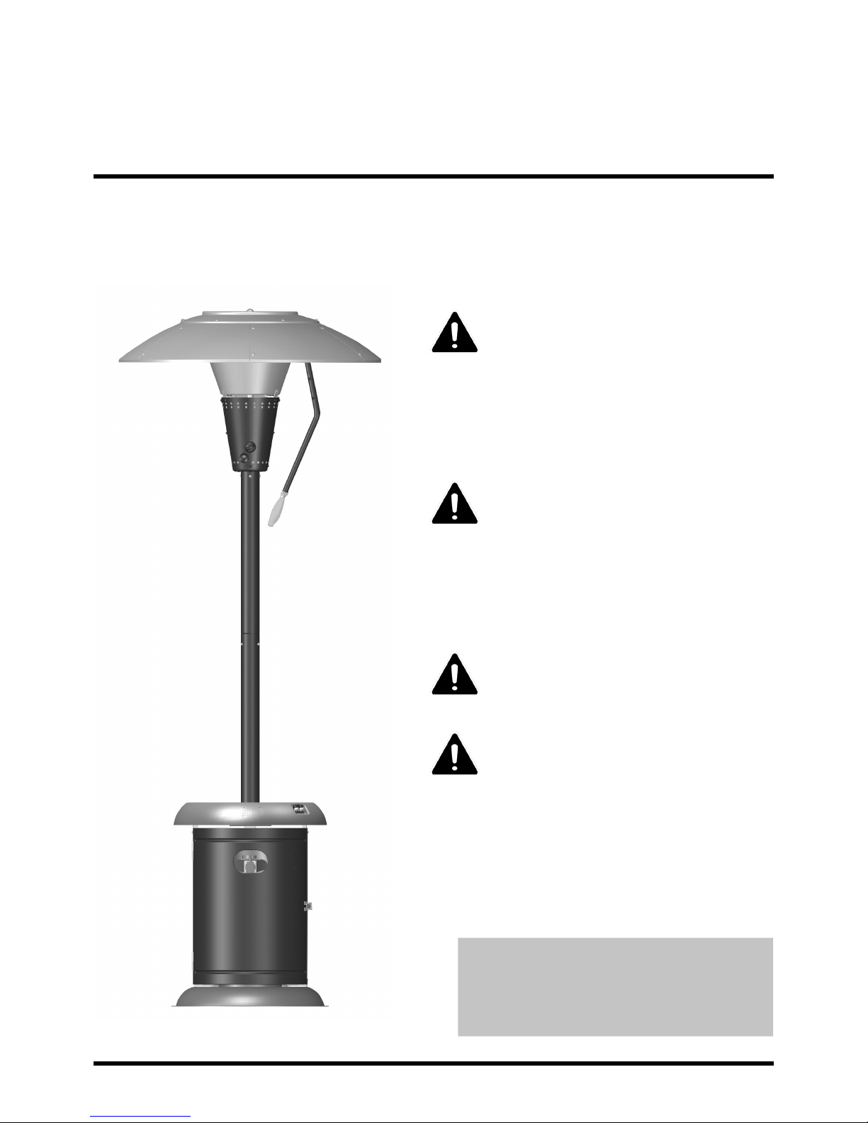
Mirage 38,200Btu
Heat Focusing Patio Heater with Speaker + Light
These instructions are for your safety. Please read them
thoroughly before use and retain them for future reference.
DANGER:
If you smell gas:
1. Shut o gas to the appliance.
2. Extinguish any open ame.
3. If odor continues, keep away from
the appliance and immediately call
your gas supplier or re department.
WARNING:
Do not store or use gasoline or other
ammable vapors and liquids in the
vicinity of this or any other appliance.
An LP-cylinder not connected for use
shall not be stored in the vicinity of any
other appliance.
WARNING:
For Outdoor Use Only.
WARNING:
Improper installation, adjustment,
alteration, service or maintenance can
cause injury or property damage.
Read the installation, operating and
maintenance instructions thoroughly
before installing or servicing this
equipment.
We provide a Customer Support Service.
If you have any queries please contact us
on info@uigroup.ie or tel. (678) 534 2876
or visit our website www.uigroup.ie
Patent No: US 8,176,910132
Ref Description Illustration Qty Ref Description Illustration Qty
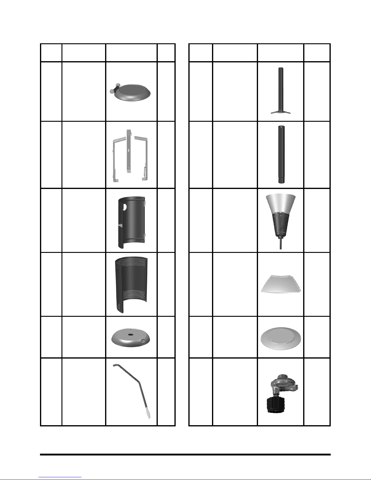
Parts Supplied
1
2
3
4
5
6
Base
Cylinder
Chamber
Supports
Cylinder
Chamber
Door
Cylinder
Chamber
Wall
Drinks
Table
Reector
Handle
1
3
1
1
1
1
7
8
9
10
11
12
Lower
Support
Pole
Upper
Support
Pole
Lantern
Parasol
Side
Panels
Parasol Top
Panel
Regulator
1
1
1
6
1
1
Page 1
Page 2
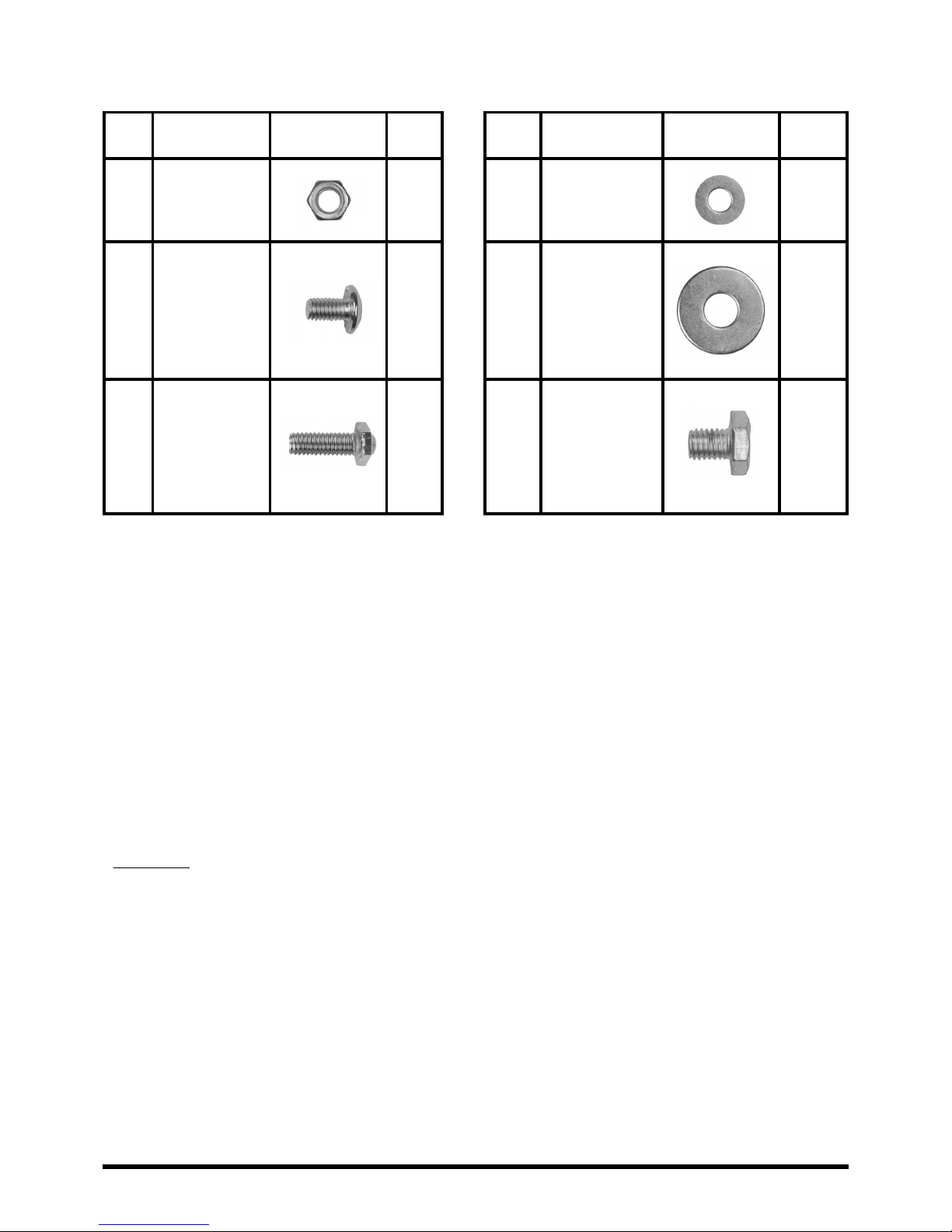
Fixings Supplied
Ref Description Illustration Qty Ref Description Illustration Qty
A
B
C
1/4″ Nut
1/4″ Dome
Head Bolt
1/4″ Dome
Hex Bolt
33
24
22
D
E
F
1/4″ Washer
5/16″
Washer
5/16″ Bolt
22
3
3
Fixings are shown at actual size.
Before You Start
• Check the contents of the box and make sure you have all the parts and ttings listed. If not,
contact the factory by email: info@uigroup.ie or the Helpline (678) 534 2876
• When you are ready to start, make sure that you have the right tools at hand, plenty of space
and a clean dry area for assembly.
Assembly
• Please lay out all nuts and bolts and check lengths before assembly. It is recommended that
the carton is cut open and spread out on the oor and used as a protective surface during
assembly. Refer to the assembly diagrams as necessary.
• Important - while every precaution has been made in the manufacture of this product, care
must be taken during assembly in case sharp edges are present.
Page 3
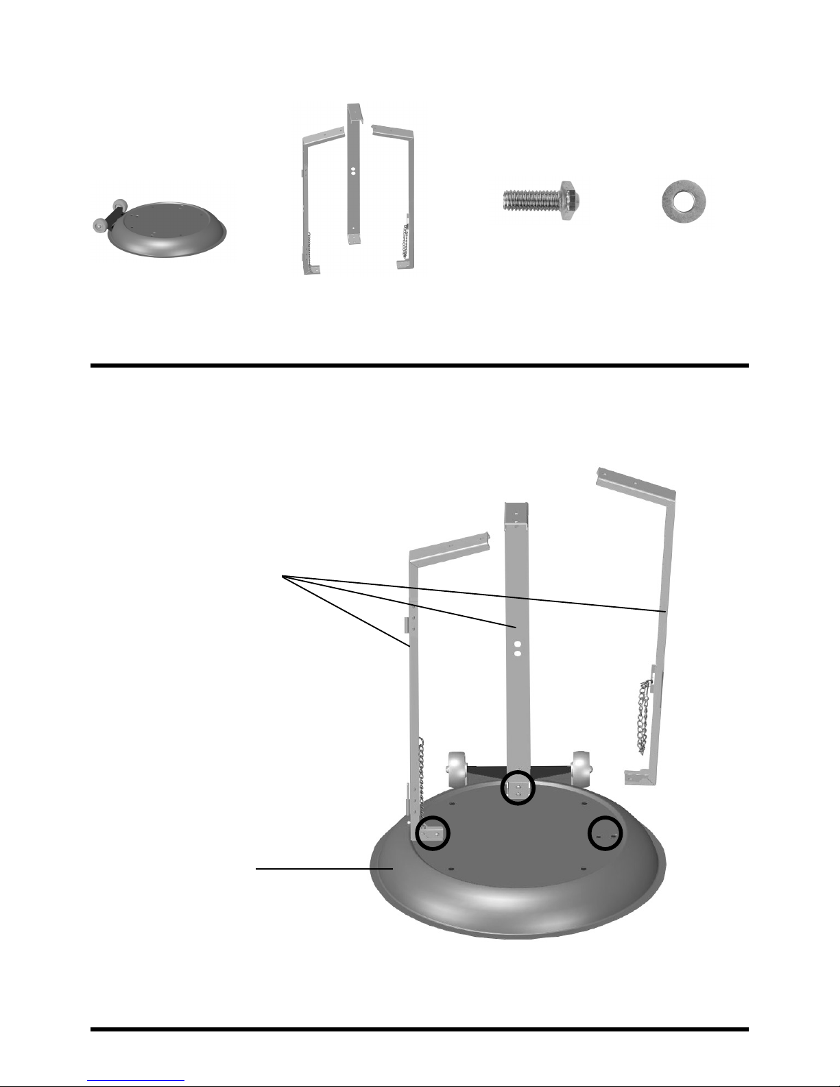
Assembly Step 1
Base Cylinder Chamber
Supports (A,B,C)
1/4″ bolt (C)
Fix the cylinder chamber supports (A,B,C) to corresponding location on the base with 6 of the
1/4″ bolts (Ref. C) and washers (Ref. D). Finger tighten only.
Cylinder chamber
supports
Base
1/4″ washer (D)
Page 4
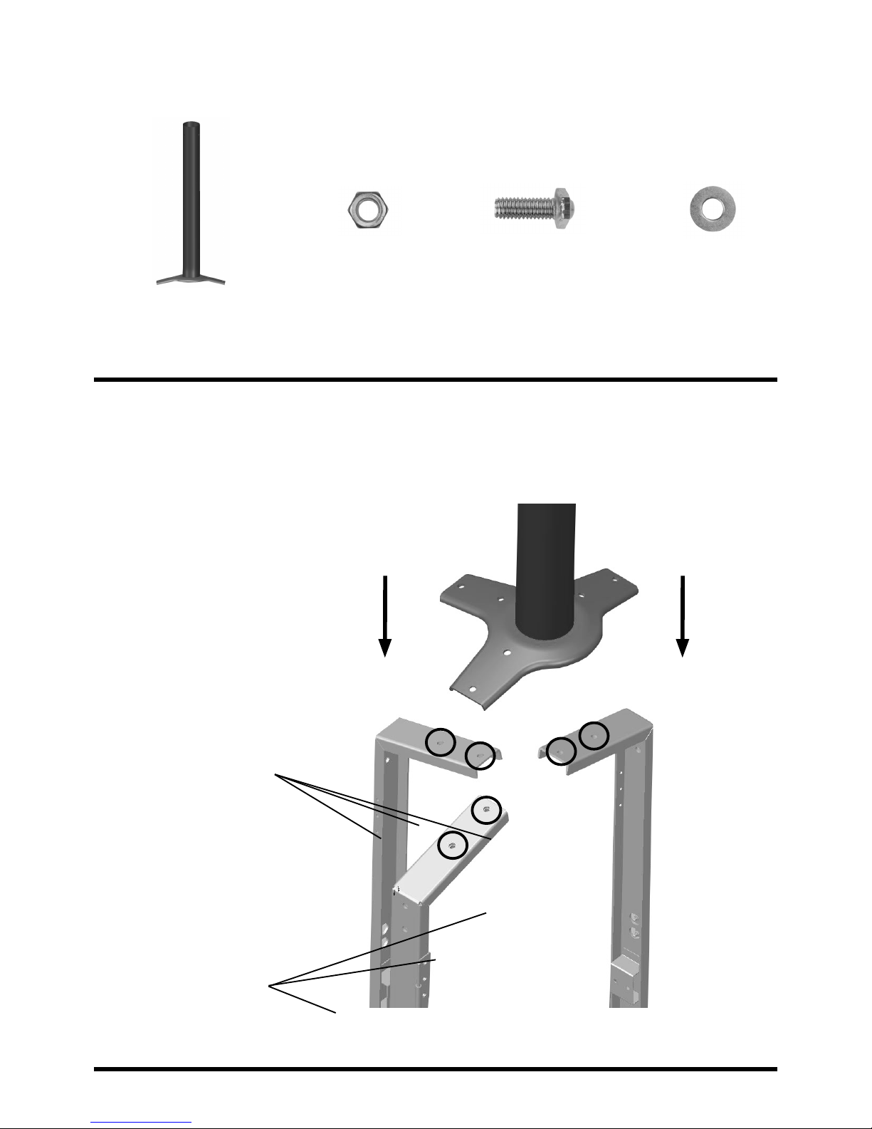
Assembly Step 2
Lower
Support Pole
1/4″ Nut (A) 1/4″
Dome Hex Bolt (C)
Fix lower support pole to cylinder chamber supports as shown using 6 of the 1/4″ bolts
(Ref. C) and 6 of the 1/4″ nuts (Ref. A) and washers (Ref. D). Finger tighten only.
1/4″ Bolt
Cylinder chamber
supports
1/4″
Washer (D)
Page 5
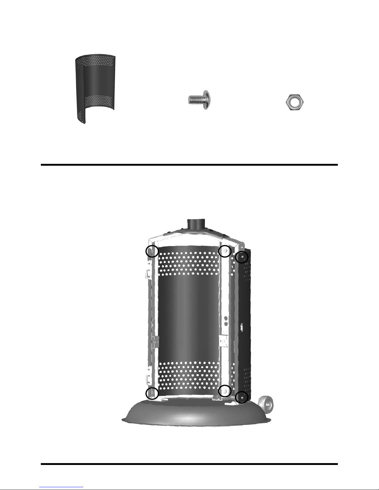
Assembly Step 3
Cylinder
Chamber Wall
1/4″ Dome
Head Bolt (B)
1/4″ Nut
(A)
Fit the cylinder chamber wall to the cylinder chamber supports using 6 of the 1/4″ dome head
bolts (Ref. B) and 6 of the 1/4″ nuts (Ref. A). Finger tighten only.
 Loading...