

Miracle Water MW-40 Owner's Manual
!"#$%&'()#*)+
!"#$%"$&'()%'()$')*$"+,-'%,
$."/-$0(-'12,$3'%,-
03456
3'%,-$7"8%,),-
!"#$%&'(%)*+,-.
..................................................AUTOMATIC WATER SOFTENER
WARRANTY
TEN YEAR LIMITED WARRANTY
GENERAL CONDITIONS
Damage to any part of this water softener because of misuse, misapplication, neglect, alteration, accident, installation or operation contrary to our
printed instructions, or damage caused by any unusual force of nature such as, but not limited to, freezing, flood, hurricane, tornado, or earthquake
is not covered by this warranty. In all such cases, regular parts and service charges will apply.
We assume no warranty liability in connection with this water softener other than specified herein. This warranty is in lieu of all other warranties,
expressed or implied, including warranties of fitness for a particular purpose. We do not authorize any person or representative to assume for us
any other obligations on the sale of this water softener.
Should a defect or malfunction occur, contact your contractor. If you are unable to contact your contractor, return the part, freight prepaid, directly to
the factory at the address below. Enclose with the part a full description of the problem, with your name, full address, date purchased, model and
serial numbers, and selling contractor’s name and address. We will repair or replace the part and return it to you at no cost if our repair department
determines it to be defective under the terms of the warranty.
This warranty gives you specific legal rights and you may have other rights which vary from province to province.
This water softener is manufactured by Miracle Water, 5240 Bradco Blvd., Mississauga, ON L4W 1G7; customer information telephone no. 1-800356-7851.
WARRANTY POLICY
Miracle Water, Mississauga, ON, warrants this water softener as stated herein:
From the date of installation, within the warranty period described below, we will repair or replace any part which we find defective because of faulty
materials and workmanship, or corrosion. You pay only freight to our factory and local labor charges.
* ONE YEAR ON COMPLETE UNIT
*THREE YEARS ON ELECTRONIC CONTROL * THREE YEARS ON CONTROL VALVE BODY
* FIVE YEARS ON SALT STORAGE TANK * TEN YEARS ON MINERAL TANK, EXCLUDING MINERAL
SAFETY GUIDES
FOLLOW THE INSTALLATION INSTRUCTIONS CAREFULLY. FAILURE TO INSTALL THE SOFTENER PROPERLY VOIDS
THE WARRANTY.
BEFORE YOU BEGIN INSTALLATION, READ THIS ENTIRE MANUAL. THEN, OBTAIN ALL THE MATERIALS AND TOOLS
YOU WILL NEED TO MAKE THE INSTALLATION.
CHECK LOCAL PLUMBING AND ELECTRICAL CODES. THE INSTALLATION MUST CONFORM TO THEM. CONSULT WITH
YOUR LICENSED PLUMBER.
USE ONLY LEAD-FREE SOLDER AND FLUX FOR ALL SWEAT-SOLDER CONNECTIONS.
USE CARE WHEN HANDLING THE SOFTENER. DO NOT TURN UPSIDE DOWN, DROP, OR SET ON SHARP
PROTRUSIONS.
DO NOT LOCATE THE SOFTENER WHERE FREEZING TEMPERATURES OCCUR. DO NOT ATTEMPT TO TREAT WATER
OVER 120°F. FREEZING, OR HOT WATER DAMAGE VOIDS THE WARRANTY.
AVOID INSTALLING IN DIRECT SUNLIGHT. EXCESSIVE SUN HEAT MAY CAUSE DISTORTION OR OTHER DAMAGE TO
NON-METALLIC PARTS.
THE SOFTENER REQUIRES A MINIMUM WATER FLOW OF 3 GALLONS PER MINUTE AT THE INLET. MAXIMUM
ALLOWABLE INLET WATER PRESSURE IS 125 PSI. IF DAYTIME PRESSURE IS OVER 80 PSI, NIGHTTIME PRESSURE
MAY EXCEED THE MAXIMUM. USE A PRESSURE REDUCING VALVE IF NECESSARY. ( ADDING A PRESSURE REDUCING
VALVE MAY REDUCE THE FLOW.)
THE SOFTENER WORKS ON 24 VOLT-60 Hz ELECTRICAL POWER ONLY. BE SURE TO USE THE INCLUDED
TRANSFORMER AND PLUG IT INTO A NOMINAL 120V, 60 CYCLE HOUSEHOLD OUTLET THAT IS GROUNDED AND
PROPERLY PROTECTED BY AN OVER CURRENT DEVICE SUCH AS A CIRCUIT BREAKER OR FUSE. IF TRANSFORMER
IS REPLACED, USE ONLY THE AUTHORIZED SERVICE, CLASS II, 24 VOLT, 10VA TRANSFORMER.
THIS SYSTEM IS NOT INTENDED TO BE USED FOR TREATING WATER THAT IS MICROBIOLOGICALLY UNSAFE OR OF
UNKNOWN QUALITY WITHOUT ADEQUATE DISINFECTION BEFORE OR AFTER THE SOFTENER.
2

..................................................AUTOMATIC WATER SOFTENER
UNPACKING / INSPECTION
The softener is shipped in one carton. It is completely
assembled at the factory, except as required at
installation.
Be sure to check the entire softener for any shipping
damage or parts loss. Also note damage to the
shipping cartons. Contact the transportation company
TABLE OF CONTENTS
WARRANTY, SAFETY GUIDES ...................................................................................................................2
SPECIFICATIONS, DIMENSIONS ...............................................................................................................4
BEFORE STARTING INSTALLATION .........................................................................................................5
TYPICAL INSTALLATION ILLUSTRATION .................................................................................................6
INSTALLATION STEPS .......................................................................................................................... 7 - 9
PROGRAMMING THE MW-40 DEMAND TIMER ................................................................................ 10 -11
SANITIZING PROCEDURES .....................................................................................................................11
WATER AND WATER CONDITIONING ............................................................................................. 12 - 13
HOW THE WATER SOFTENER WORKS .......................................................................................... 13 - 14
GENERAL WATER SOFTENER MAINTENANCE ............................................................................. 15 - 16
MW-40 DEMAND TIMER FEATURES, SETTINGS, AND SERVICE ................................................. 17 - 24
TIMER DISPLAYS .................................................................................................................................17
OPTIONAL RECHARGE CONTROLS .......................................................................................... 17 - 18
PROGRAM MEMORY ...........................................................................................................................18
RECHARGE (START) TIME, MAXIMUM DAYS BETWEEN REGENERATIONS,
EFFICIENCY MODE, 97% FEATURE, HEAVY DUTY BACKWASH ........................................... 18 - 19
MODEL CODE, 12 OR 24 HOUR CLOCK, GALLONS OR LITERS MEASURE...................................20
AUTOMATIC ELECTRONIC DIAGNOSTICS .......................................................................................21
ELECTRONIC SYSTEM PROFILE .......................................................................................................21
HOW TO SEND AND ESP TRANSMISSION ........................................................................................22
SERVICE CHECKOUT PROCEDURES ..............................................................................................23
MANUAL INITIATED ELECTRONICS DIAGNOSTIC.................................................................... 23 - 24
MANUAL ADVANCE REGENERATION CHECK ..................................................................................24
WIRING SCHEMATIC ...........................................................................................................................24
WATER FLOW THROUGH VALVE.............................................................................................................25
REPAIR PARTS ................................................................................................................................. 26 - 29
PARTS RETURN TAGS ..............................................................................................................................31
for all damage and loss claims. The manufacturer is
not responsible for damages in transit.
Small parts, needed to install the softener, are in a
parts bag. To avoid loss of the small parts, keep them
in the parts bag until you are ready to use them.
PAGE
NO.
3
..................................................AUTOMATIC WATER SOFTENER
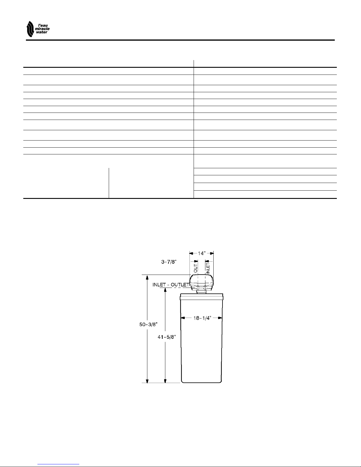
SPECIFICATIONS / DIMENSIONS
MODEL MW-40
RATED CAPACITY
RATED EFFICIENCY !
AMOUNT OF HIGH CAPACITY RESIN (lbs / cu ft)
RESIN TANK NOMINAL SIZE (in., dia x height)
SERVICE FLOW RATE (gpm)
PRESSURE DROP AT SERVICE FLOW
WATER SUPPLY MAXIMUM HARDNESS (gpg)
WATER SUPPLY MAX. CLEAR WATER IRON (ppm) "
See Rating Decal, Located On The Softener
See Rating Decal, Located On The Softener
55.1 / 1.06
9 x 40
10
14
110
8
WATER PRESSURE LIMITS (min. / max. psi) #
WATER TEMPERATURE LIMITS (oF)
WATER SUPPLY MINIMUM FLOW RATE (gpm)
REGENERATION CYCLE FLOW RATES (gpm)
FILL (flow to brine tank)
BRINING
BRINE RINSE
BACKWASH
FAST RINSE
These systems conform to NSF/ANSI 44 for specific performance claims as verified and substantiated by test data.
! Efficiency rating is only valid at the lowest salt dosage. These softeners were efficiency rated according to NSF/ANSI Standard 44.
" Capacity to reduce clear water iron is substantiated by WQA test data.
# Canada working pressure: 1.4 – 7.0 kg/cm2.
(flow to drain)
20 – 125
40 – 120
3
.3
0.22
0.15
2.0
2.0
MW-40
4

..................................................AUTOMATIC WATER SOFTENER
BEFORE STARTING INSTALLATION
! WHERE TO INSTALL THE SOFTENER.....................................................................................
! Place the softener as close as possible to the
pressure tank (well system) or water meter (city
water).
! Place the softener as close as possible to a floor
drain, or other acceptable drain point (laundry tub,
sump, standpipe, etc.).
! Connect the softener to the main water supply pipe
BEFORE or AHEAD OF the water heater. DO NOT
RUN HOT WATER THROUGH THE SOFTENER.
Temperature of water passing through the
softener must be less than 120oF (49oC).
! Keep outside faucets on hard water to save soft
water and salt.
! Do not install the softener in a place where it could
freeze. Damage caused by freezing is not covered
by the warranty.
! TOOLS, PIPE and FITTINGS, OTHER MATERIALS YOU WILL NEED (see page 6) ..............
! Put the softener in a place water damage is least
likely to occur if a leak develops. The manufacturer will
not repair or pay for water damage.
! A 120 volt electric outlet, to plug the included
transformer into, is needed within 10 feet of the
softener. The transformer has an attached 10 foot
power cable. Be sure the electric outlet and
transformer are in an inside location, to protect
from wet weather.
! If installing in an outside location, you must take the
steps necessary to assure the softener, installation
plumbing, wiring, etc., are as well protected from the
elements, contamination, vandalism, etc., as when
installed indoors.
! Keep the softener out of direct sunlight. The sun’s
heat will melt plastic parts
! In and out fittings included with the softener are 1”
(nominal) copper sweat tubes. To maintain full valve
flow, 1” pipes to and from the softener fittings are
recommended. You should maintain the same, or
larger, pipe size as the water supply pipe, up to the
softener inlet and outlet.
! Use copper, brass, or galvanized pipe and fittings.
Some codes may also allow CPVC plastic pipe.
! ALWAYS install the included bypass valve, or 3
shut–off valves. Bypass valves let you turn off water
to the softener for repairs if needed, but still have
water in the house pipes.
! Drain hose (5/8” inside diameter) is needed for the
valve drain. See step 5 on page 8. A 15’ length of
hose is included with some models.
! A length of 3/8” or 7/16” inside diameter hose is
needed for the salt tank drain. A 7’ length of hose is
included with some models. If a longer length is
needed, you can buy good quality, thick-wall, flexible
hose at most hardware stores or supply houses.
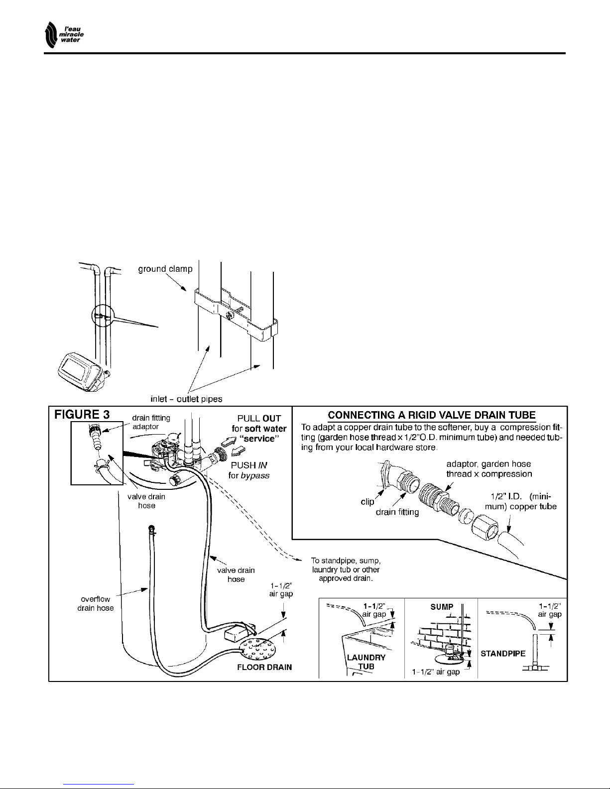
! If a rigid valve drain is needed, to comply with
plumbing codes, you can buy the parts needed (see
page 8) to connect a ½ in. copper tubing drain.
! Nugget or pellet water softener salt is needed to fill
the brine tank (see page 9, 10 and 16).
! PLAN HOW YOU WILL INSTALL THE SOFTENER ..................................................................
You must first decide how to run in and out pipes to
the softener. Look at the house main water pipe at the
point where you will connect the softener. Is the pipe
soldered copper, glued plastic, or threaded
brass/galvanized? What is the pipe size?
Now look at the typical INSTALLATION illustration on
page 6. Use it as a guide when planning your
particular installation. Be sure to direct raw, hard
water to the softener valve inlet fitting. The valve is
marked IN and OUT.
5
..................................................AUTOMATIC WATER SOFTENER
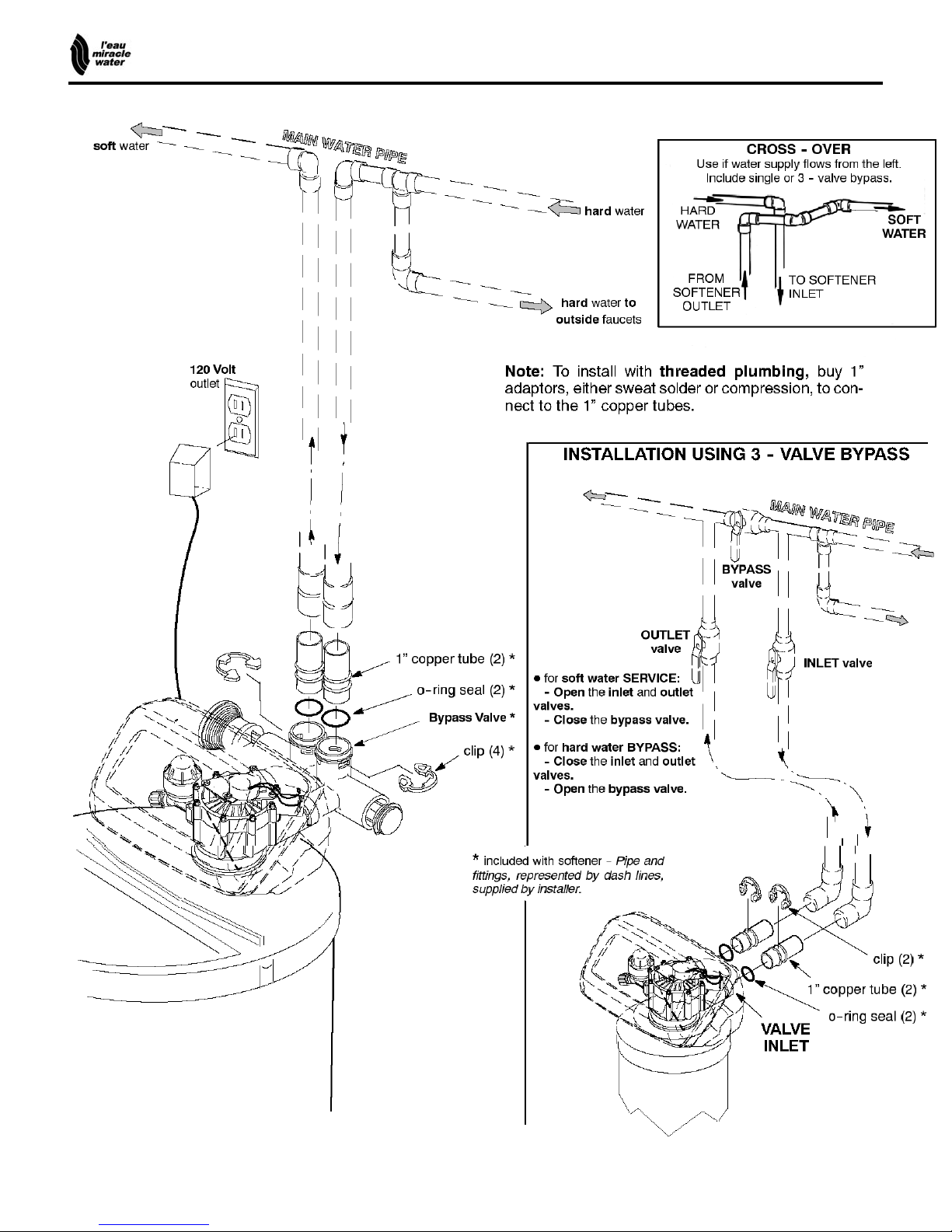
TYPICAL SOLDERED COPPER or CPVC
6
..................................................AUTOMATIC WATER SOFTENER
INSTALLATION STEPS
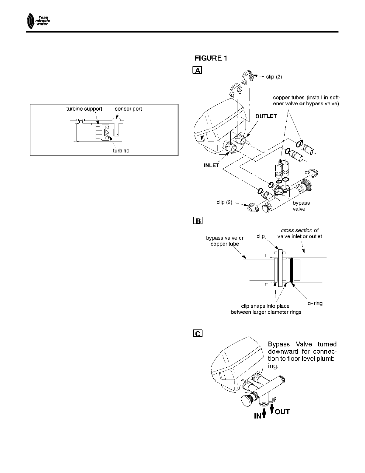
1. INSTALL BYPASS VALVE and/or COPPER
TUBES
NOTE: Before installing the copper tubes or bypass valve,
be sure the turbine and support are firmly in place, in the
valve outlet. Blow into the valve port and observe the
turbine for free rotation.
" Slide copper tubes, with lubricated o-ring seals in
place, into the valve inlet and outlet ports, Figure 1A
- OR –
" Push the bypass valve, with lubricated o-ring seals in
place, into the valve inlet and outlet ports, Figures 1A and
1C
" Snap the two large plastic clips in place, from the top,
down, Figures 1A and 1B. Be sure they snap into place.
Pull on the copper tubes, or bypass valve, to make
sure they held securely in place.
2. INSTALL THE BRINE TANK OVERFLOW
FITTINGS
" Insert the rubber grommet into the ¾” diameter hole in
the brine tank sidewall, see page 9.
" Push the barbed end of the hose adaptor elbow into
the grommet.
3. MOVE THE SOFTENER ASSEMBLY INTO
INSTALLATION POSITION
" Be sure the installation surface is level and smooth. If
needed, place the tank on a section of ¾” thick (min.)
plywood. Then, place shims under the plywood as needed
to level the softener.
4. PLUMB IN AND OUT PIPES TO AND FROM
SOFTENER
CAUTIONS: Observe all of the following cautions while
you connect inlet and outlet plumbing.
" Turn off the house water supply valve and open
faucets to relieve pressure in the pipes.
" BE SURE RAW, HARD WATER IS DIRECTED TO
THE VALVE INLET PORT.
" Be sure to use bypass valve(s).
continued
7
..................................................AUTOMATIC WATER SOFTENER
INSTALLATION STEPS, continued
" If making a soldered copper installation, do all sweat
soldering before connecting pipes to the softener
fittings. Torch heat will damage plastic parts.
" When turning threaded pipe fittings onto plastic fittings,
use care not to cross-thread.
" Use pipe joint compound on all external pipe threads.
" Support inlet and outlet plumbing in some manner (use
pipe hangers) to keep the weight off of the valve fittings.
5. INSTALL GROUNDING CLAMP (IF NEEDED):
" To maintain electrical ground continuity in the house cold
water piping, install the included ground clamp as shown.
Be sure the pipes are clean under the clamps, to assure
good contact.
6. CONNECT AND RUN THE VALVE DRAIN
HOSE:
" Take a length of 5/8” inside diameter hose and attach
to the valve drain fitting.
" Locate the other end of the hose at a suitable drain
point...floor drain, sump, laundry tub, etc. Check and
comply with local codes.
IMPORTANT: If a longer length of hose is needed, buy
and use high quality, thick-wall hose that will not easily
kink or collapse. The water softener will not work if water
cannot exit this hose during regenerations.
" Tie or wire the hose in place at the drain point. Water
pressure will cause it to whip during the backwash and
fast rinse cycles of regeneration. Also provide an air gap
of at least 1-1/2” between the end of the hose and the
drain point. An air gap prevents possible siphoning of
sewer water, into the softener, if the sewer should ‘‘backup’’.
" If raising the drain hose overhead is required to get to
the drain point, do not raise higher than 8’ above the
floor. Elevating the hose may cause a back-pressure
that could reduce brine draw during regenerations.
continued
8

..................................................AUTOMATIC WATER SOFTENER
INSTALLATION STEPS, CONTINUED
7. CONNECT AND RUN THE BRINE TANK
OVERFLOW HOSE:
This drain is for safety only. If the brine tank should
over-fill with water, the excess is carried to the drain.
" Attach a length of hose (included with some
models) to the drain elbow, installed in step 2, page 7.
Use a hose clamp to hold it in place.
" Locate the other end of the hose at the drain point.
Do not elevate this hose higher than the elbow on the
brine tank. Do not tee this hose to the valve d in hose.
8. FLUSH PIPES, EXPEL AIR FROM
SOFTENER, AND TEST YOUR
INSTALLATION FOR WATER LEAKS:
CAUTION: To avoid water or air pressure damage
to softener inner parts, be sure to do the following
steps exactly as listed.
A. Fully open two cold, soft water faucets nearby the
softener.
B. Place bypass valve(s) in ‘‘bypass’’ position. On a
single valve, slide the stem inward to BYPASS, see
page 8. On a 3-valve system, close the inlet and outlet
valves, and open the bypass valve, see page 6.
C. Fully open the house main water pipe shutoff valve.
Observe a steady flow from both opened faucets.
D. Place bypass valve(s) in ‘‘service”, EXACTLY as
follows. KEEP SOFT WATER FAUCETS OPEN.
1. SINGLE BYPASS VALVE: SLOWLY, pull the
valve stem outward to ‘‘service’’, pausing several
times to allow the softener to pressurize slowly.
2. 3-VALVE BYPASS: Fully close the bypass
valve and open the outlet valve. SLOWLY, open
the inlet valve, pausing several times to allow the
softener to pressurize slowly.
E. After about three minutes, open a HOT water
faucet for one minute, or until all air is expelled, then
close.
F. Close both cold water faucets.
G. Check your plumbing work for leaks and fix right
away, if any are found. Be sure to observe previous
caution notes.
H. Turn on the gas or electric supply to the water
heater. Light the pilot, if applicable.
9. ADD WATER AND SALT TO THE BRINE
TANK:
" Remove the salt storage area cover. Add about
three gallons of water into the tank. Do not add into
the brinewell.
"Fill the tank with NUGGET, PELLET or coarse
SOLAR water softener salt. Do not use rock, block,
granulated, and ice cream making salts, or salt with
iron removing additives. Also see page 16. Salt
storage capacity is 200 lbs or more (varies by model).
Note: If the softener is installed in a humid basement
or other damp area, it is better to fill the tank with less
salt, more frequently (see salt bridging in the
maintenance section). Eighty to 100 lbs of salt will last
for several months, depending on water hardness,
family size, and model of softener.
10. CONNECT TO ELECTRICAL POWER:
" The softener works on 120 volt, 60 Hz electric
power. The included transformer changes standard
120 volt AC house power to 24 volts. Plug the
transformer into a 120 volt outlet only. Be sure the
outlet is always ‘‘live’’ so it can not be switched off by
mistake.
11. PROGRAM THE MW-40 DEMAND
TIMER, page 10.
9
..................................................AUTOMATIC WATER SOFTENER
PROGRAMMING THE MW-40 DEMAND TIMER
MW-40
MW-40
" TIMER SETTINGS REQUIRED...upon installation, and after an extended power outage (see Program Memory,
page 19).
NOTES:
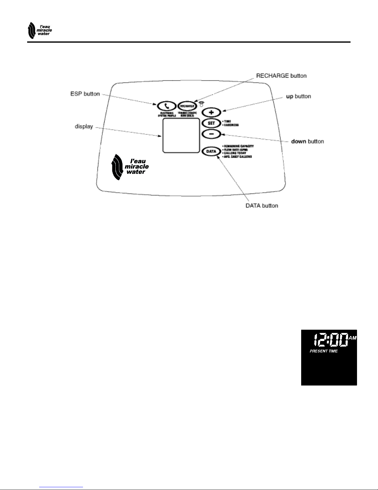
# WHEN THE TRANSFORMER IS PLUGGED INTO THE ELECTRICAL OUTLET (STEP 10, ABOVE), 12:00AM
(flashing), and PRESENT TIME show in the upper display area. Program the timer as follows. If A- - - is flashing,
please see Model Code setting on page 20.
# A ‘‘beeper’’ sounds while pressing buttons for timer programming. One beep signals a change in the timer display.
Repeated beeps means the timer will not accept a change from the button or arrow you have pressed, and you
should use another.
# To program the timer, you will use the either SET, UP or DOWN buttons.
! SET PRESENT TIME OF DAY....................................................................................................
NOTE: If the words PRESENT TIME do not show in the display, press the SET button until they do.
1. Press the SET, UP or DOWN button to set. The UP
button moves the display ahead; the DOWN button
moves the time backward.
NOTE: Each press of the UP or DOWN button arrow
changes the time by one minute. Holding the buttons
in changes the time 32 minutes each second.
2. When the present time shows, press SET to apply.
If the present time is between
noon and midnight, be sure PM
shows.
If the present time is between
midnight and noon, be sure AM
shows.
10
 Loading...