

Mira Zest User Manual
7.5 and 8.5 kW
back
ELECTRIC SHOWERS
Installation
Operation &B
Maintenance Guide
THESE INSTRUCTIONS ARE TO BE LEFT WITH THE USER
1

Contents
Page
Introduction ................................................................... 3
Important Safety Information .................................................... 4
Pack Contents Checklist .......................................................... 6
Dimensions ................................................................... 7
Wiring Diagram ................................................................... 8
Specifications ............................................................................ 8
Installation Requirements......................................................... 9
Installation ................................................................. 13
Commissioning ....................................................................... 15
Operation ................................................................................. 17
Maintenance ............................................................................ 21
Fault Diagnosis ....................................................................... 26
Spare Parts .............................................................................. 28
Accessories ............................................................................. 30
Notes ................................................................................. 31
Guarantee, Customer Care Policy, and How to contact us
.............................................................................. Back cover
2

Introduction
Thank you for purchasing a quality Mira product. To enjoy the full potential of your new
product, please take time to read this guide thoroughly, having done so, keep it handy for
future reference.
The Mira Zest electric showers have separate controls for power selection and temperature/
flow adjustment. A unique flow regulator stabilises temperature changes caused by water
pressure fluctuations. These can result from taps being turned on or off or toilets being
flushed.
Appliances covered by this guide:
Mira Zest 7.5 - A 7.5 kW 240 V AC (6.9 kW 230 V AC) heater with a Mira React adjustable
spray handset. Supplied complete with flexible hose, adjustable clamp bracket assembly,
slide bar and supports and hose retaining ring. Available in white finish.
Mira Zest 8.5 - A 8.5 kW 240 V AC (7.8 kW 230 V AC) heater with a Mira React adjustable
spray handset. Supplied complete with flexible hose, adjustable clamp bracket assembly,
slide bar and supports and hose retaining ring. Available in white finish.
If you experience any difficulty with the installation or operation of your new shower
control, then please refer to the Maintenance and Fault diagnosis section, before
contacting Caradon Plumbing Solutions. Our telephone and fax numbers can be
found on the back cover of this guide.
3

Section
Important Safety Information
WARNING!
1.1. Products manufactured by us are safe and without risk provided they are installed,
used and maintained in good working order in accordance with our instructions and
recommendations.
1.2. THIS APPLIANCE MUST BE EARTHED.
In accordance with the current edition of ‘The Plugs and Sockets etc. (Safety)
Regulations' in force at the time of installation. This appliance is intended to be
permanently connected to the fixed electrical wiring of the mains system.
1.3. DO NOT twist the individual cable cores of the liv e and neutral conductors, as this
will prevent them from entering the terminal block.
1.4. The shower unit must not be fitted where it may be exposed to freezing conditions.
Make sure that any pipework that could become frozen is properly insulated.
1.5. DO NOT operate this appliance if it is frozen. Allow the appliance to thaw before
using again.
1.6. DO NOT operate this appliance if water leaks from the pressure relief valve,
maintenance will be required before the appliance can be safely used.
1.7. DO NOT fit any form of outlet flow control as the outlet acts as a vent for the tank
body . Only Mir a recommended outlet fittings should be used.
1.8. There are no user serviceable components beneath the cover of the appliance.
Only a competent tradesperson should remove the co ver .
1.9. If any of the following conditions occur, isolate the electricity and water supplies
and refer to “To contact us”, on the bac k page of this guide.
1.9.1. If the cover is not correctly fitted and water has entered the appliance
case.
1.9.2. If the case is damaged.
1.9.3. If the appliance begins to make an odd noise, smell or smoke.
1.9.4. If the appliance shows signs of a distinct change in performance, indicating
a need for maintenance.
1.9.5. If the appliance is frozen.
1.10. Isolate the electrical and water supply bef ore removing the cov er.
1.11. Mains connections are exposed when the cover is removed.
1.12. Refer to the wiring diagram before making any electrical connections.
1.13. Ensure all electrical connections are tight, to prevent overheating.
4

Caution!
2.1. Read all of these instructions and retain this guide for later use.
2.2. Pass on this guide in the e v ent of change of ownership of the installation site .
2.3. Follow all warnings, cautions and instructions contained in this guide, and on or
inside the appliance.
2.4. The electrical installation must comply with the “Requirements for Electrical
Installations” commonly ref erred to as the IEE Wiring Regulations, or an y particular
regulations and practices, specified by the local electricity supply company in force
at the time of installation. The installation should be carried out by an electrician or
contractor who is registered, or is a member of, an association such as:
2.4.1. National Inspection Council for Electrical Installation and Contracting (NICEIC),
throughout the UK.
2.4.2. The Electrical Contractors Association (ECA), England and Wales.
2.4.3. The Electrical Contractors Association of Scotland (ECAS).
2.5. This is a high power unit; it is essential to contact your electricity supply company
to ensure that the electricity supply is adequate for the purpose.
2.6. The plumbing installation must comply with the requirements of UK Water
Regulations/Bye-laws (Scotland), Building Regulations or any particular regulations
and practices, specified by the local water company or water undertakers. The
installation should be carried out by a plumber or contractor who is registered, or is
a member of, an association such as:
2.6.1. Institute of Plumbing (IOP), throughout the UK.
2.6.2. National Association of Plumbing, Heating and Mechanical Services
Contractors (NAPH & MSC), England and W ales.
2.6.3. Scottish and Northern Ireland Plumbing Employers’ Federation (SNIPEF),
Scotland and Northern Ireland.
2.7. Anyone who may have difficulty understanding or operating the controls of any
shower should be attended whilst showering. Particular consideration should be
given to the young, the elderly, the infirm, or anyone inexperienced in the correct
operation of the controls.
2.8. When this appliance has reached the end of its serviceable life, it should be disposed
of in a safe manner , in accordance with current local authority recycling, or waste
disposal policy.
5
Section
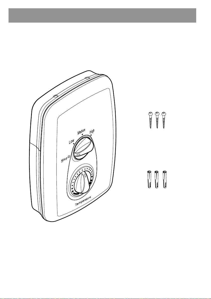
Pack Contents Checklist
Tick the appropriate boxes to familiarize yourself with the part names and to confirm that the
parts are included.
1. Mira Zest 7.5 or 8.5 kW
1 x Mira Zest 7.5 or 8.5
3 x Fixing Screws
3 x Wall Plugs
2. Documentation
1 x Installation, Operation and Maintenance Guide
1 x Customer Support Brochure
6
Section
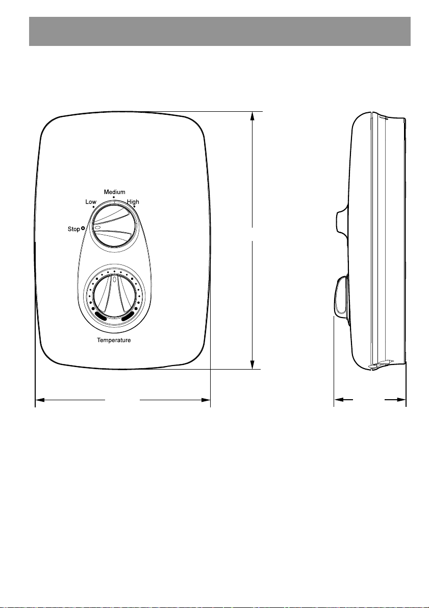
Dimensions
297 mm
202 mm
81 mm
7
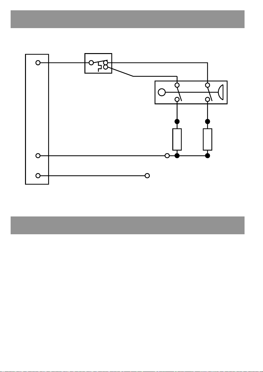
Wiring Diagram
Thermal Cutout
Dual Disc
P
89 Brown
Pressure/ON/OFF/Power
/Selector Switch
97 Brown
96 Red
88 Red 86 Brown
Load
N
90 Blue
E
91 Green
Tank Connection
Specifications
Plumbing
1. Minimum maintained inlet pressure 0.7 bar for satisfactory operation.
2. Maximum static inlet pressure 10 bar.
3. Minimum static pressure 0.2 bar to keep the flow valve closed.
Electrical
1. The appliance requires a 40 Amp fuse.
2. The terminal block will not accept cable larger than 10 mm2.
Standards and Approvals
1. This Mira Zest complies with all the relevant directives for CE marking.
8

Installation Requirements
Plumbing
1. The appliance is designed to operate with a minimum maintained inlet pressure
of 0.7 bar up to a maximum static inlet pressure of 10 bar.
2. The appliance is normally connected to the cold water mains-fed supply. Howe ver ,
the water supply can be taken from a cold water storage cistern, provided there is a
minimum maintained inlet head of water of 7 metres (the vertical distance from the
base of the cold water storage cistern to the shower fitting handset). To reduce
pressure losses and fluctuations, the cistern-fed water supply must be independent
from other supply draw-offs, and should avoid long horizontal pipe runs and use
swept bends rather than 90° elbows.
3. The appliance is suitable for installation within the shower area. It is fitted with a
pressure relief device and must be positioned over a water catchment area with the
controls at a convenient height f or the user .
4. The appliance is fitted with a plastic inlet connector intended to connect to a 15 mm
compression fitting supplied from the top, bottom or back.
5. Do not fit the appliance to the wall and tile up to the case. The appliance must be
fitted onto a finished flat and even w all surface. This is important as difficulty may
be encountered when fitting the cover and subsequent operation of the unit could be
impaired (small pillars moulded on to the back of the case allow air circulation).
6. Refrain from applying excessive force when making any connections. Always provide
mechanical support when making the plumbing connections.
7. Do not install the appliance in a position where it may become frozen. The
shower unit must not be fitted where it may be e xposed to freezing conditions. The
shower unit must not be used if suspected of being frozen.
8. We recommend that a non-restrictive (free flowing) isolating valve is fitted in the
cold water supply pipe to allow the complete maintenance of the appliance. Do not
use a valve with a loose washer plate (jumper) as this can lead to a build up of static
pressure.
9. T o a void damage to the case when soldered fittings are used, pre-solder the pipework
and fittings before connecting them to the inlet stub.
10. The appliance is fitted with a ½ " BSP male outlet thread, to accept a Mira shower
hose.
11. Supply pipework MUST be flushed to clear debris before connecting the appliance.
9
12. When installed in very hard water areas (above 200 ppm temporary hardness) your
installer may advise the installation of a water treatment device, to reduce the
effects of limescale formation. Appliance malfunction due to excessive limescale
formation is not covered by the manuf acturer’ s guarantee. Y our local w ater company
will be able to advise the hardness of water in your area.
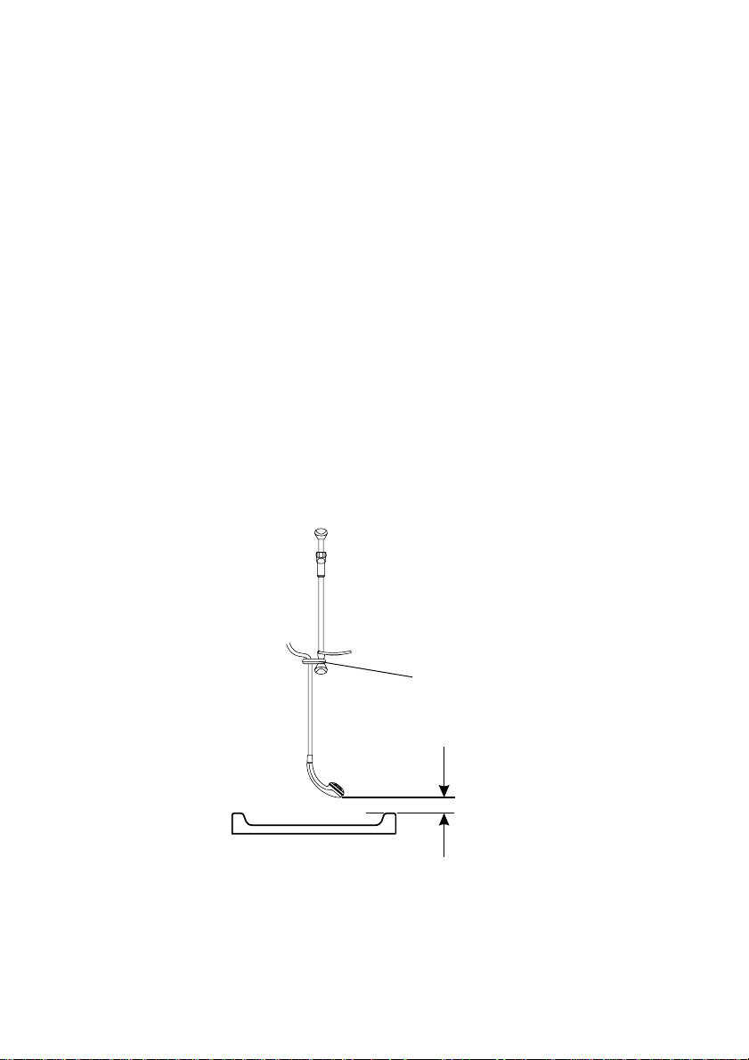
13. A hose retaining ring is supplied to prevent the handset from dropping below the
spillover le vel of the bath or showe r , which could lead to contamination from backsiphonage (refer to Figure 1). The supplied hose retaining ring should meet the great
majority of user requirements for shower installations with flexible outlet fittings.
However, there will be occasions when the hose retaining ring will not provide a
suitable solution. In these instances an outlet double checkvalve, e.g. the Mira
DCV-H, must be fitted. The inclusion of the Mira DCV-H will increase the required
supply pressure typically by 0.1 bar .
Double checkvalves, fitted in the inlet supply to the appliance, cause a pressure
build-up, which could exceed the maximum static inlet pressure for the appliance.
14. Water flow can be obtained without the electrical power being connected. This allows
the plumbing connections to be tested prior to final connection of the electrical
supply.
15. Avoid layouts where the shower hose will be sharply kinked. This may reduce the
life of the hose.
10
Hose Retaining
Ring
25 mm Minimum
Spill-over
Level
Figure 1
 Loading...