

Mira Sprint User Manual
|
5kW |
|
. |
5and |
9 |
|
|
. |
|
8 |
|
Power |
|
Low |
Flow |
|
|
Temperature
Start
Stop
ELECTRIC SHOWERS
Installation & User Guide
THESE INSTRUCTIONS ARE TO BE LEFT WITH THE USER
1

CONTENTS |
|
Introduction ............................................................................................. |
3 |
Important Safety Information ................................................................ |
4 |
Pack Contents Checklist ......................................................................... |
6 |
Dimensions.............................................................................................. |
7 |
Wiring Diagram ...................................................................................... |
8 |
Specifications ......................................................................................... |
9 |
Plumbing .............................................................................................. |
9 |
Electrical .............................................................................................. |
9 |
Standards and Approvals ..................................................................... |
9 |
Installation Requirements ...................................................................... |
9 |
Installation ............................................................................................ |
13 |
Commissioning ..................................................................................... |
16 |
Maintenance ......................................................................................... |
18 |
General .............................................................................................. |
18 |
Cleaning ............................................................................................. |
18 |
Operation .............................................................................................. |
23 |
Fault Diagnosis ..................................................................................... |
27 |
Spare Parts ........................................................................................... |
32 |
Notes ...................................................................................................... |
34 |
Customer Service ................................................................................. |
36 |
2

INTRODUCTION
Thank you for purchasing a quality Mira product. To enjoy the full potential of your new product, please take time to read this guide thoroughly. Having done so, keep it handy for future reference.
The Mira Sprint is a range of electric showers having separate controls for power selection and temperature/flow adjustment. A unique flow regulator stabilises temperature changes caused by water pressure fluctuations. These can result from taps being turned on or off or toilets being flushed.
Mira Sprints covered by this guide:
Mira Sprint 8.5 - An 8.5 kW 240 V AC heater with a Mira Response adjustable spray handset with three different spray actions (start, force and soothe). Individual lights indicate 'POWER' and 'LOW FLOW'. Supplied complete with flexible hose, adjustable clamp bracket assembly, soap dish, slide bar and supports and hose retaining ring. Available in white/chrome finish.
Mira Sprint 9.5 - A 9.5 kW 240 V AC heater with a Mira Response adjustable spray handset with three different spray actions (start, force and soothe). Individual lights indicate 'POWER' and 'LOW FLOW'. Supplied complete with flexible hose, adjustable clamp bracket assembly, soap dish, slide bar and supports and hose retaining ring. Available in white/chrome finish.
If you experience any difficulty with the installation or operation of your new shower control, then please refer to the Maintenance and Fault Diagnosis section, before
contacting Mira Showers. Our telephone and fax numbers can be found on the back cover of this guide.
3

IMPORTANT SAFETY INFORMATION
Please read all of these instructions and retain this guide for later use.
1.Please pass on this guide in the event of change of ownership of the installation site.
2.Follow all warnings, cautions and instructions contained in this guide, and on the appliance.
3.Make sure you know how to isolate the water and electricity supply.
4.This appliance is not thermostatic and can produce scalding temperatures if not operated in accordance with the instructions given in this manual.
5.Make sure that you fully understand how to operate this shower and make sure that it is properly maintained in accordance with the instructions given in this manual.
6.Anyone who may have difficulty understanding or operating the controls of any shower should be attended whilst showering. Particular consideration should be given to:
•the young, the elderly, the infirm, the disabled, anyone who suffers from a medical condition that can result in temporary incapacity (e.g. epilepsy or blackouts) and anyone inexperienced in the correct operation of the controls.
7.Sunburn or skin conditions can increase your sensitivity to hot water. Make sure that you set the shower to a cooler temperature.
8.The installation should be carried out by a competent installer who is familiar with electrical and plumbing systems (refer to INSTALLATION REQUIREMENTS for further details).
9.The shower unit must not be exposed to freezing conditions. If the shower is to be left for long periods of time (e.g. holiday) we would recommend that supplies to the shower are isolated.
10.DO NOT fit any form of outlet flow restriction (trigger handset). Use only Mira recommended fittings.
11.If any of the following conditions occur, isolate the electricity and water supplies and refer to “To contact us”, on the back page of this guide.
•If the cover is not correctly fitted and water has entered the appliance case.
•If the case is damaged.
•If the appliance begins to make an odd noise, smell or smoke.
•If the appliance shows signs of a distinct change in performance, indicating a need for maintenance.
•DO NOT operate if water leaks from this appliance.
•Warning! DO NOT operate the appliance if it is frozen. If suspected of being frozen, alow to thaw and contact installer before using again.
4
12.When this appliance has reached the end of its serviceable life, it should be disposed of in a safe manner, in accordance with current local authorityrecycling, or waste disposal policy.
13.This product is not suitable for areas of very high humidity (i.e. Steam rooms). Contact your installer for more advice.
14.Turn off the electrical and water supplies before commencing installation.The electricity must be turned off at the mains and the appropriate circuit fuse removed, if applicable.
15.Mains connections are exposed when the cover is removed.
16.Refer to the wiring diagram before making any electrical connections.
17.Having completed the installation, make sure that the user is familiar with the operation of the appliance.
18.The electrical installation must comply with the “Requirements For Electrical Installations” commonly referred to as the IEE Wiring Regulations, or any particular regulations and practices, specified by the local electricity supply company in force at the time of installation. The installation should be carried out by an electrician or contractor who is registered Part P (Building Regulations) and is a member of, an association such as:
•National Inspection Council for Electrical Installation and Contracting (NICEIC), throughout the UK.
•The Electrical Contractors Association (ECA), England and Wales.
•The Electrical Contractors Association of Scotland (ECAS).
19.The installation must must comply with relevant building regulations and water regulations.The installation should be carried out by a plumber or contractor who is registered, or is a member of, an association such as:
•Institute of Plumbing (IOP), throughout the UK.
•National Association of Plumbing, Heating and Mechanical Services Contractors (NAPH & MSC), England and Wales.
•Scottish and Northern Ireland Plumbing Employers’ Federation (SNIPEF), Scotland and Northern Ireland.
20.THIS APPLIANCE MUST BE EARTHED. ENSURE SUPPLEMENTARY BONDING COMPLIES WITH THE “REQUIREMENTS FOR ELECTRICAL INSTALLATIONS”.
In accordance with the current edition of ’The Plugs and Sockets etc. (Safety) Regulations’ in force at the time of installation, this Mira Sprint is intended to be permanently connected to the fixed electrical wiring of the mains system.
21.DO NOT commission this appliance if water leaks from the unit or the heater tank pressure relief valve.
22.Ensure all electrical connections are tight, to prevent overheating.
23.Do not remove the internal splash-guard from the unit.
5
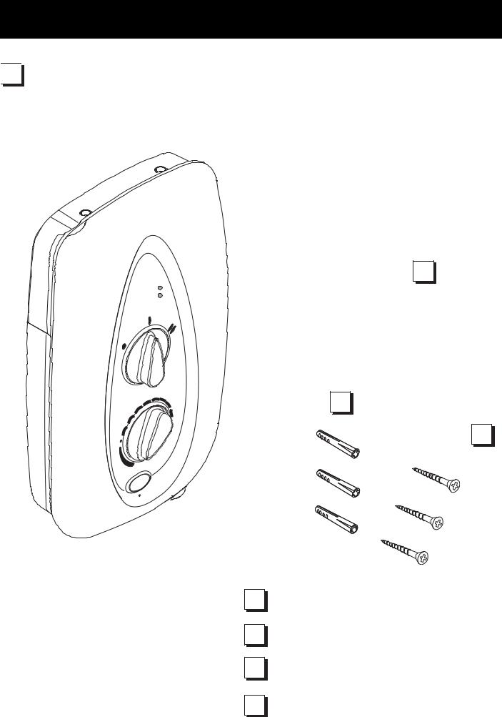
PACK CONTENTS CHECKLIST


 Tick the appropriate boxes to familiarize yourself with the part names and to confirm
that the parts are included.
1. Mira Sprint 8.5 and 9.5
|
|
er |
|
Po |
w |
||
low |
|||
|
|
||
w |
F |
||
Lo |
|
|
|
ature Temper
1 x Mira Sprint 8.5 and 9.5
1 x Olive
1 x Compression Nut
3 x Wall Plug
3 x Fixing Screws
|
|
tart |
Sto |
p |
S |
|
||
|
|
2. Documentation
1 x Installation and User Guide
1 x Installation Template
1 x Customer Support Brochure
1 x Installer Checklist
6
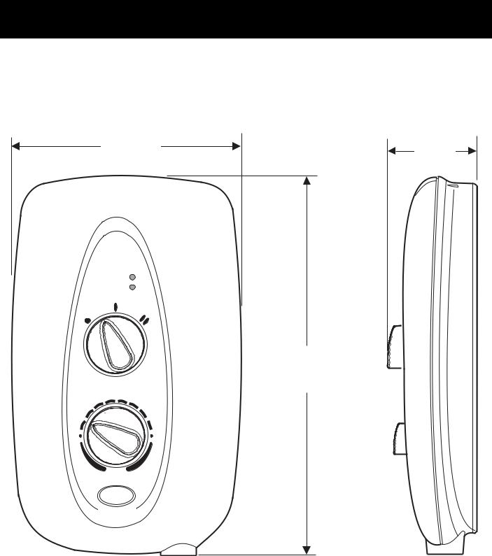
DIMENSIONS
203.5 mm |
79 mm |
|
Power
Low Flow
342 mm
Temperature
Stop Start
Start
7

WIRING DIAGRAM
Start Stop
Stop
Internal Wiring Diagram
Mira Sprint
Power
Low Flow
Double-pole
Isolating Switch
Isolating Valve
Mains-fed Cold
Water Supply
Temperatur e
Stop Start
Start
Clamp
Bracket
Hose
Retaining
Ring
Shower Tray
Electrical Schematic Diagram
8

SPECIFICATIONS
Plumbing
1.Minimum maintained inlet pressure 70 kPa (0.7 bar) for satisfactory operation.
2.Maximum static inlet pressure 1000 kPa (10 bar).
3.Minimum static pressure 20 kPa (0.2 bar) to keep the flow valve closed.
Electrical
1.The Mira Sprint requires a 40 Amp fuse.
2.The terminal block will not accept cable larger than 16 mm2 .
Standards and Approvals
1.This Mira Sprint complies with all relevant directives for CE marking.
INSTALLATION REQUIREMENTS
Plumbing
1.The Mira Sprint is designed to operate with a minimum maintained inlet pressure of 70 kPa (0.7 bar) up to a maximum static inlet pressure of 1000 kPa (10 bar).
2.The Mira Sprint must be connected to the cold water mains-fed supply. If you can only cistern feed your shower, Mira produce a pumped electric shower (Elite 2) designed for this particular application.
3.The Mira Sprint is suitable for installation within the shower area. It is fitted with a pressure relief device and must be positioned over a water catchment area with the controls at a convenient height for all users.
4.The Mira Sprint is fitted with a plastic inlet connector intended to connect to a 15 mm compression fitting, supplied from the top, bottom or back.
9
5.Do not fit the Mira Sprint to the wall and tile up to the case.The Mira Sprint must be fitted on to a finished, flat and even wall surface (this wall surface should be tiled or waterproofed). This is important as difficulty may be encountered when fitting the cover. Also the operation of the unit could be impaired due to lack of air flow (small pillars moulded on to the back of the case allow air circulation).
6.Refrain from applying excessive force when making any connections. Always provide mechanical support when making the plumbing connections.
7.Warning! Do not install the Mira Sprint in a position where it may become frozen. The shower unit must not be fitted where it may be exposed to freezing conditions. Do not operate the unit if suspected of being frozen.
8.We recommend that a non-restrictive (free flowing) isolating valve is fitted in the cold water supply pipe to allow the complete maintenance of the Mira Sprint. Do not use a valve with a loose washer plate (jumper) as this can lead to a build up of static pressures.
9.To avoid damage to the case when soldered fittings are used, pre-solder the pipework and fittings before connecting them to the inlet connector assembly.
10.The Mira Sprint is fitted with a ½ " BSP male outlet thread, to accept a Mira shower hose.
11.BEFORE connecting the Mira Sprint, thoroughly flush the mains-fed cold water supply pipe with a minimum of 10 litres of water. The supply must be clean and free from debris.
12.When installed in very hard water areas (above 200 ppm temporary hardness) your installer may advise the installation of a water treatment device, to reduce the effects of limescale formation. Mira Sprint malfunction due to excessive limescale formation is not covered by the manufacturer’s guarantee.Your local water company will be able to advise you of the hardness of water in your area.
13.A hose retaining ring is supplied to prevent the handset from dropping below the spillover level of the bath or shower, which could lead to contamination from backsiphonage (refer to Figure 1).The supplied hose retaining ring should meet the great majority of user requirements for shower installations with flexible outlet fittings. However, there will be occasions when the hose retaining ring will not provide a suitable solution. Double checkvalves, fitted in the inlet supply to the appliance,
cause a pressure build-up, which could exceed the maximum static inlet pressure for the appliance. In these instances an outlet double checkvalve, e.g. the Mira DCV-H, must be fitted. The inclusion of the Mira DCV-H will increase the required supply pressure typically by 0.1 bar.
10
14.Avoid layouts where the shower hose will be sharply kinked. This may reduce the life of the hose.
Hose Retaining
Ring
Hose Retaining
Ring
Spill-over |
25 mm Minimum |
Level |
|
25 mm Minimum
|
Spill-over |
|
Level |
Shower Tray |
Bath |
|
Figure 1
Electrical
Read the section "Important Safety Information" first.
1.In a domestic installation, the rating of the electricity supply company fuse and the consumer unit must be adequate for the additional demand. As the Mira Sprint is a high power unit, it is essential to contact your electricity supply company to ensure that the supply is adequate for the appliance.Voltage drop due to local heavy demand will reduce the shower's performance.
2.The appliance must be earthed by connecting the supply-cable earth conductor to the earth terminal.
Supplementary bonding: Within the bathroom or shower room, all accessible conductive parts of electrical equipment and extraneous conductive parts (metal parts) that are likely to introduce earth potential, must be electrically bonded to earth using a minimum cable size of 4.0 mm2 if the cable is not mechanically protected (2.5 mm2 if mechanically protected).
3.The minimum cable size (cross-sectional area) required is 6 mm2 under normal conditions of installation .
Important! The shower circuit should be separated from other circuits by at least twice the diameter of the cable or conduit and it should not be run through thermally insulating material or in locations where the ambient temperature is likely to exceed 30 °C. If any of these conditions are unavoidable it is necessary to determine the cable size which will prevent damage to the cable caused by overheating.
11
 Loading...