

Page 1
1
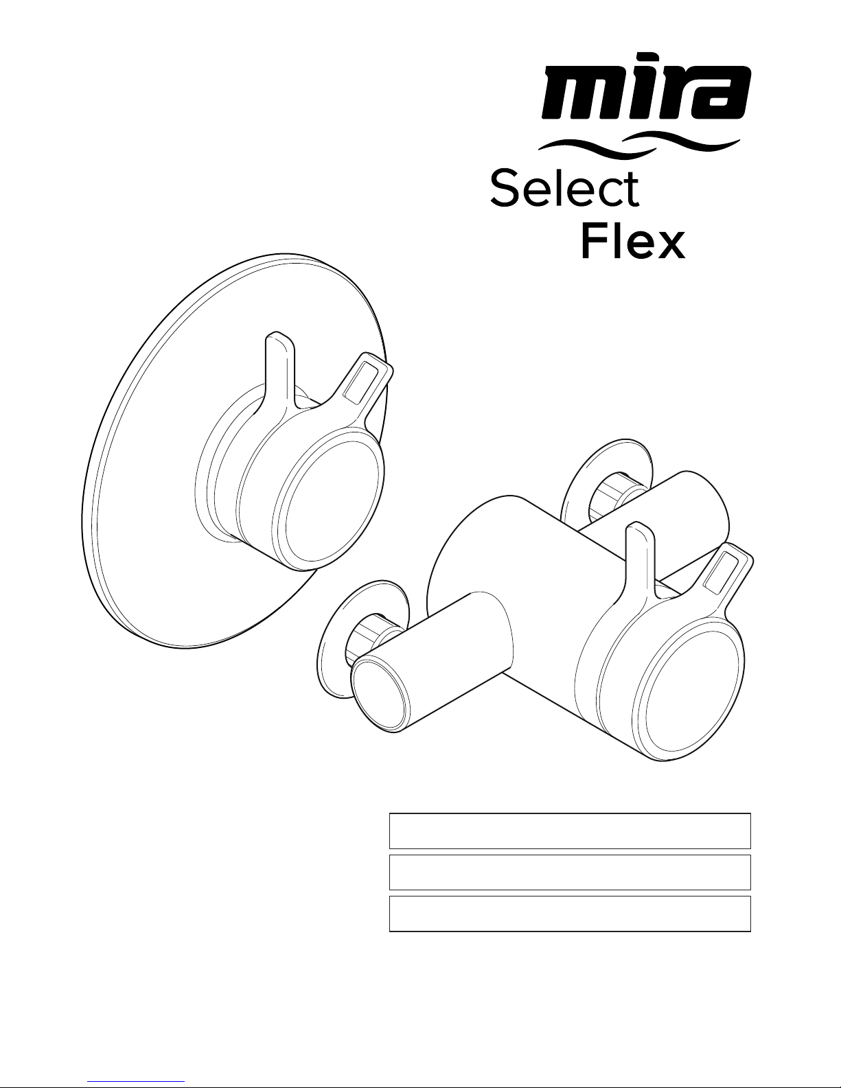
Mira Select Flex
inStallation and USer GUide
therMoStatic Mixer
These instructions must be left with the user.
Page 2

2
introdUction
thank you for purchasing a quality Mira product.
to enjoy the full potential of your new product,
please take time to read this guide thoroughly.
having done so, keep it handy for future
reference.
the Mira Select Flex is a thermostatic mixer with
separate ow and temperature controls. The lever
controls have been designed to be easily operated
by users with restricted hand movement.
the thermostatic mixer incorporates a wax
capsule temperature sensing unit, which provides
an almost immediate response to changes of
temperature of the incoming water supplies to
maintain the selected showering temperature.
an adjustable temperature stop is provided which
limits the maximum temperature to a safe level.
Inlet lters are tted to protect the thermostatic
cartridge.
on exposed models the thermostatic mixer
has adjustable inlets to fit pipework centres
between 139 mm and 153 mm and is designed
for connection to rising, falling or rear entry
pipework.
The Mira Select Flex has been certied for use
in UK healthcare premises as a type 3 valve
under the BUildcert tMV3 scheme. the Mira
Select Flex has also been certied as a Type
2 valve under the BUildcert tMV2 scheme.
For healthcare* installations refer to section:
‘Type 2 and Type 3 Valves’. this product also
complies with the Water Supply (water ttings)
regulations 1999.
*healthcare applications are hospitals, aged
person facilities, residential care homes, etc. and
any other application where the user is similarly
at risk.
if you experience any difficulty with the
installation or operation of your new
thermostatic mixer, please refer to ‘Fault
Diagnosis’, before contacting Kohler Mira ltd.
our contact details can be found on the back
cover of this guide.
contentS
Introduction 2
Guarantee 3
recommended Usage 3
Patents and design registration 3
Safety Warnings 3
Pack Contents 4
Specications 5
Pressures 5
temperatures 5
thermostatic Shut-down 5
connections 5
Flow rates 5
dimensions 6
Installation 7
Suitable Plumbing Systems 7
General 7
exposed thermostatic Mixers 8
Built-in thermostatic Mixers 10
control assembly 19
Reversed Inlet Supplies 20
Operation 21
Commissioning 22
exercising the thermostat 22
Maximum temperature 22
Maximum temperature Setting 22
Type 2 and Type 3 Valves 23
application 23
commissioning 23
Maintenance 24
Maintenance 25
General 25
Planned Maintenance 25
Fault diagnosis 27
inlet Filters 28
Notes 29
Spare Parts 30
exposed Models 30
Built-in Models 31
Customer Service
Back Page
Page 3

3
Guarantee
For domestic installations, Mira Showers
guarantee the Mira Select Flex against any defect
in materials or workmanship for a period of ve
years from the date of purchase (shower ttings
for one year).
For non-domestic installations, Mira Showers
guarantee the Mira Select Flex against any defect
in materials or workmanship for a period of one
year from the date of purchase.
For terms and conditions refer to the back cover
of this guide.
Recommended Usage
application Valve only
Valve with
Fittings
domestic
ü ü
light commercial
ü ü
heavy commercial
ü û
healthcare
ü û
Note! Heavy duty shower ttings are available
separately for use in healthcare and heavy
commercial applications, for details contact
customer Services.
Patents and Design Registration
Patents:
GB: 2 291 693, 2 392 225, 2 421 297
US: 7 240 850
euro: 1 672 257 de, Fr, GB, it, nl, Se
Patent Applications:
GB: 2 435 077, 0712546.1
US US-2006-0124758
US-2007-0221740
euro: 03254070.0
Design Registration:
000834007/01, 000834007/02,
000578463-0006
SaFety WarninGS
Mira thermostatic mixers are precision engineered
and should give continued safe and controlled
performance, provided:
1.
they are installed, commissioned, operated and
maintained in accordance with manufacturer’s
recommendations.
2.
For type 2 and type 3 installations, they
are only used for applications covered by
their approved designations, refer to section:
‘Type 2 and Type 3 Valves’.
3.
Periodic attention is given, when necessary,
to maintain the product in good functional
order.
Caution!
1.
read all of these instructions.
2. retain this guide for later use.
3. Pass on this guide in the event of change of
ownership of the installation site.
4.
Follow all warnings, cautions and instructions
contained in this guide.
5.
Anyone who may have difculty understanding
or operating the controls of any shower should
be attended whilst showering. Particular
consideration should be given to the young,
the elderly, the inrm or anyone inexperienced
in the correct operation of the controls.
this is particularly important in healthcare
procedures, such as supervised bathing where
patients are unable to respond immediately to
unsafe temperatures.
6. Rapid/Excessive movement of the ow and/or
temperature controls may result in momentary
unstable blend temperatures.
7.
care is required when adjusting flow or
temperature, make sure that the temperature
has stabilised.
8.
When this product has reached the end of its
serviceable life, it should be disposed of in a
safe manner, in accordance with current local
authority recycling, or waste disposal policy.
Page 4
4
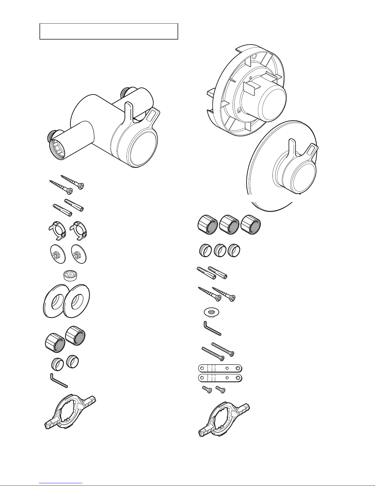
PacK contentS
tick the appropriate boxes to familiarise yourself
with the part names and to conrm that the parts
are included.
q 1 x Mira Select Flex exposed Shower control
q 1 x Mira Select Flex Built-in Shower control
(attached to the building-in shroud)
q 1 x ‘o’ Key
q 2 x olives
q 2 x compression nuts
q 3 x compression nuts
q 1 x 12 l/Min Flow regulator
q 1 x hexagon Key, 2.5 mm
q 1 x ‘o’ Key
q 2 x Screws, no 8 x 1¼”
q 2 x Wall Plugs
q 2 x olives
q 2 x concealing Plates
q 1 x hexagon Key, 2.5 mm
q 2 x Screws, no 8 x 1 ¼”
q 2 x Wall Plugs
q 2 x Securing clips
q 2 x concealing caps
q 1 x 12 l/Min Flow
regulator
Documentation
q 1 x installation template
q 1 x Mira Select Flex Built-in control assembly
q 2 x M5 x 40 mm Screws
q 2 x Securing Brackets
q 2 x Bracket Screws
Page 5

5
SPeciFicationS
For type 2 and type 3 Valves, the supply
conditions specied in section: ‘Type 2 and Type
3 Valves - Application’ take precedence over the
operating parameters which follow.
Pressures
Max Static Pressure: • 10 Bar.
Max Maintained Pressure:
• 5 Bar.
Min Maintained Pressure (Gravity System):
•
0.1 Bar (0.1 bar = 1 Metre head from cold tank
base to showerhead outlet).
Note! For gravity fed or other low pressure
systems (0.5 bar or below) do not t the outlet
ow regulator (where applicable).
For optimum performance supplies should be
•
nominally equal.
Temperatures
Factory Pre-set (Blend) Shower: • 41°C.
optimum thermostatic control range: • 35°C
to 43°C (achieved with supplies of 15°c cold,
65°C hot and nominally equal pressures).
recommended hot Supply: • 60°C to 65°C
Note! the mixing valve can operate at
higher temperatures for short periods without
damage, however this could detrimentally
affect thermostatic performance. For safety
and performance reasons it is recommended
that the maximum hot water temperature is
limited to 65°c.
cold Water range: up to• 25°C.
Minimum recommended differential between •
hot Supply and outlet temperature: 12°C.
Thermostatic Shut-down
For safety and comfort the thermostat will •
shut off the mixing valve within 2 Seconds if
either supply fails (achieved only if the blend
temperature has a minimum differential of
12°C from either supply temperature).
Connections
inlets: 15 mm compression.•
Outlet: ½” BSP Flat Face (Exposed models), •
15 mm Compression (Built-in models)
Standard connections are:
• hot - left, cold -
right, outlet - bottom (Exposed models),
top (Built-in models).
Flow Rates
typical Flow rates on low Pressure Systems,
Mira Select Flex with Mira Select Flex Shower
Fittings:
0.2
00.4
0.60.8 1
Supply Pressure (bar)
25
20
15
10
5
0
Flow Rate (l/min)
typical Flow rates on high Pressure Systems
(with 12 Litre/Min ow regulator tted in shower
control outlet), Mira Select Flex with Mira Select
Flex Shower Fittings:
0.511.522.5
Supply Pressure (bar)
33.5 4
14
12
10
8
6
4
Flow Rate (l/min)
Page 6
6
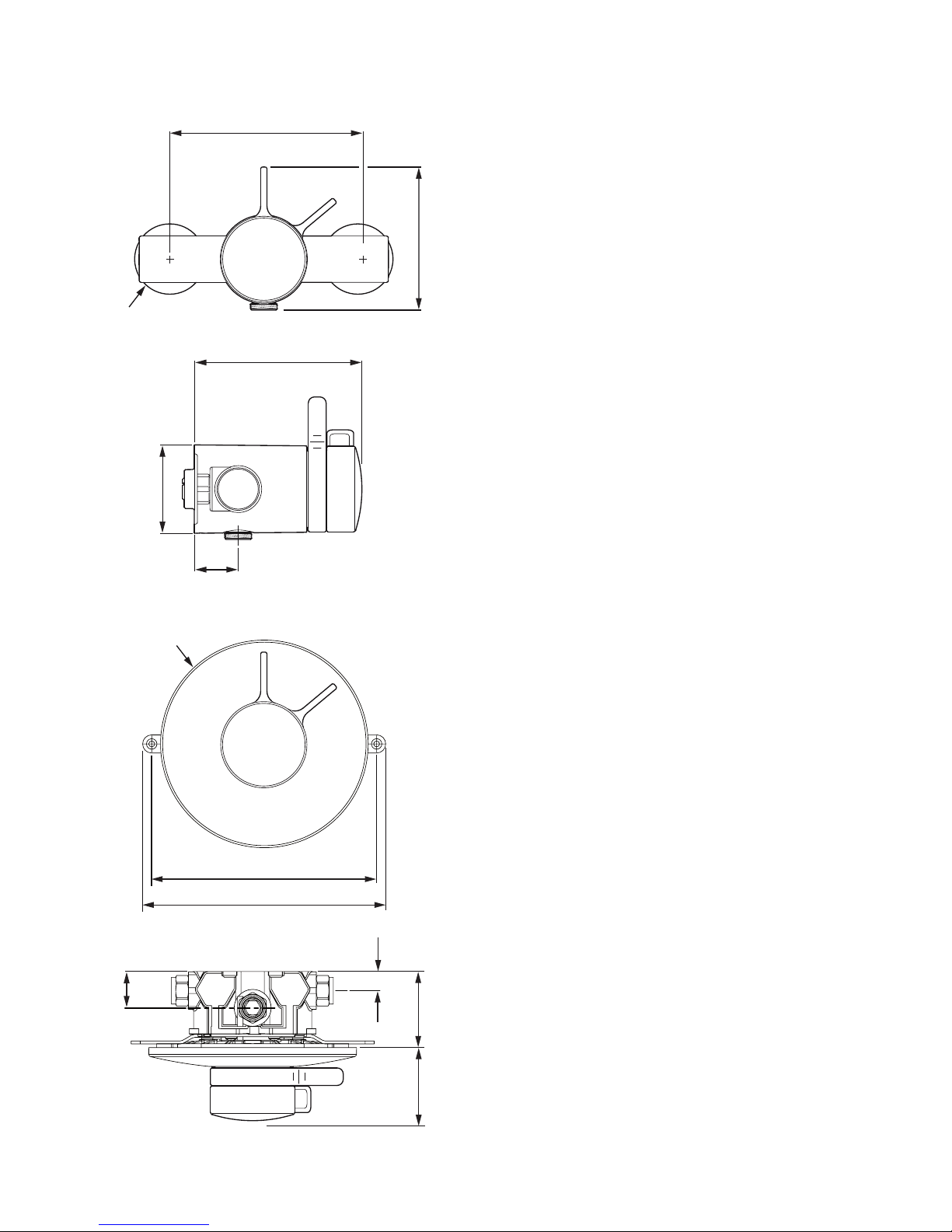
139 - 153
134
Ø71
35
198
214
Ø56
Ø183
114
all dimensions are in mm.
32
17
69 67-85
Dimensions
Page 7
7
inStallation
Suitable Plumbing Systems
Gravity Fed:
the thermostatic mixer must be fed from a cold
water cistern (usually tted in the loft space) and
a hot water cylinder (usually tted in the airing
cupboard) providing nominally equal pressures.
Mains Pressurised Instantaneous Hot Water
System (Combination Boiler):
the thermostatic mixer can be installed with
systems of this type with balanced pressures.
(recommended Minimum Maintained Pressure:
1.0 Bar).
Unvented Mains Pressure System:
the thermostatic mixer can be installed with an
unvented, stored hot water system.
Pumped System:
the thermostatic mixer can be installed with an
inlet pump (twin impeller). The pump must be
installed in a suitable location and in accordance
with its instructions.
General
installation must be carried out in accordance
with these instructions, and must be conducted by
designated, qualied and competent personnel.
the installation must comply with the “Water
Supply Regulations 1999 (Water Fittings)” or any
particular regulations and practices, specied by
the local water company or water undertakers.
Note! Make sure that all site requirements
correspond to the information given in section:
‘Specications’. For type 2 and type 3 Valves
see also supply conditions in section: ‘Type 2 and
Type 3 Valves’.
1. the mixer must not be installed in an area
where it may freeze.
2.
For stud partitions alternative xings may be
required.
3.
‘Full bore’ isolating valves must be installed
close to the mixer for ease of maintenance.
4.
Pipework must be rigidly supported and avoid
any strain on the connections.
5.
Pipework dead-legs should be kept to a
minimum.
6.
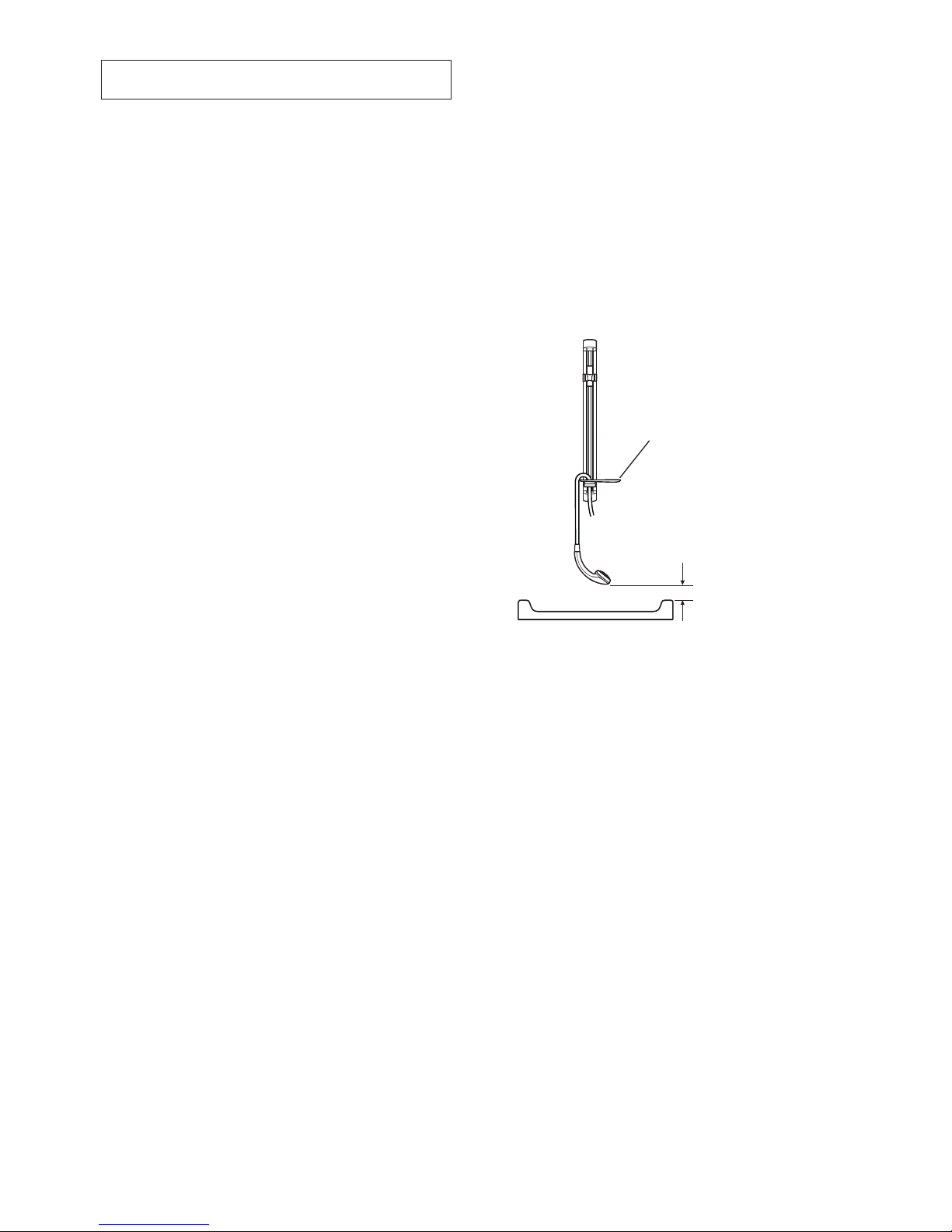
decide on a suitable position for the mixer.
the position of the mixer and the shower
ttings must provide a minimum gap of 25 mm
between the spill-over level of the shower tray/
bath and the showerhead (refer to illustration).
this is to prevent back-siphonage. For further
information on the installation of your shower
ttings, refer to the ttings installation and
user guide.
Note! Only use shower ttings recommended
by the manufacturer or supplier.
hose retaining ring
25 mm Minimum
Spill-over
level
Important! a hose retaining ring should be
tted to prevent the showerhead from dropping
below the spillover level of the shower tray/
bath, which could lead to contamination from
back-siphonage. this hose retaining ring
should meet the majority of user requirements
for shower installations with exible outlet
fittings. however, there will be occasions
when the hose retaining ring will not provide a
suitable solution. in these instances an outlet
double checkvalve, e.g. the Mira dcV-h, must
be tted. The inclusion of the Mira DCV-H
will increase the required supply pressure
typically by 10 kPa (0.1 bar), refer to section:
‘Accessories’.
Page 8
8
Exposed Thermostatic Mixers
Installing the Thermostatic Mixer
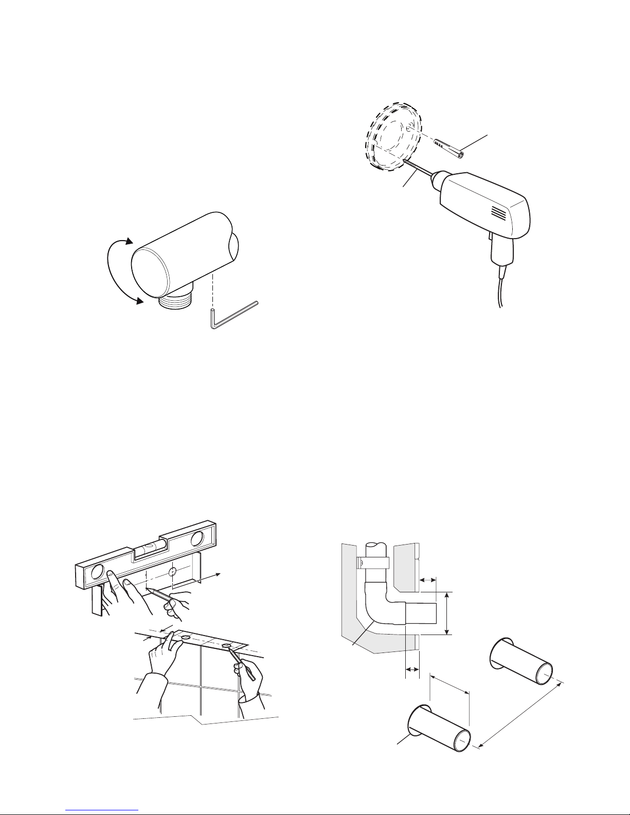
1.
the thermostatic mixer can be installed with
rear, rising or falling supply inlets. decide
on the most appropriate method for your
installation, and if necessary, loosen the
grubscrews and rotate the inlet elbows to
suit.
Important! Make sure that the elbows are
pushed fully onto the mixer before tightening
the grubscrews, do not overtighten.
2. Use the installation template to mark the
positions of the holes for the backplate and
the pipe centres.
For rising or falling supplies the pipe positions
should be set 35 mm from the centre of pipe
to the nished wall at 153 mm centres.
Note! allow a minimum of 150 mm either side
of the mixer to allow servicing of the hot and
cold inlet lters.
Note! the thermostatic mixer has adjustable
inlets to t existing pipework centres between
139 mm and 153 mm.
35 mm
allow a minimum of
150 mm either side
of mixer to wall
3. For solid walls drill the holes for the backplate
with a 6 mm drill and insert the wall plugs. For
other types of wall structure alternative xings
may be required (not supplied).
6 mm drill
Wall Plug
4. For Rear Entry Supplies Only:
a) drill the holes for the supply pipes at
153 mm centres.
b) recess the inlet holes Ø32 mm x 10 mm
deep to allow for the concealing plates.
Note! Depth must be sufcient to prevent
the concealing plates fouling on the
plumbing elbows.
5. Fit the supply pipework: Hot - Left, Cold
- Right. the inlet pipework should extend
13 mm from the nished wall surface.
Note! if it is not possible to install the mixer
with this pipework conguration complete the
installation then refer to section: ‘Reversed
Inlet Supplies’.
10 mm minimum
between elbow
and nished wall
surface
Ø32 mm
13 mm from nished
wall surface
elbow
recess Ø32 mm
x 10 mm deep
13 mm
153 mm
HOT
COLD
Page 9
9
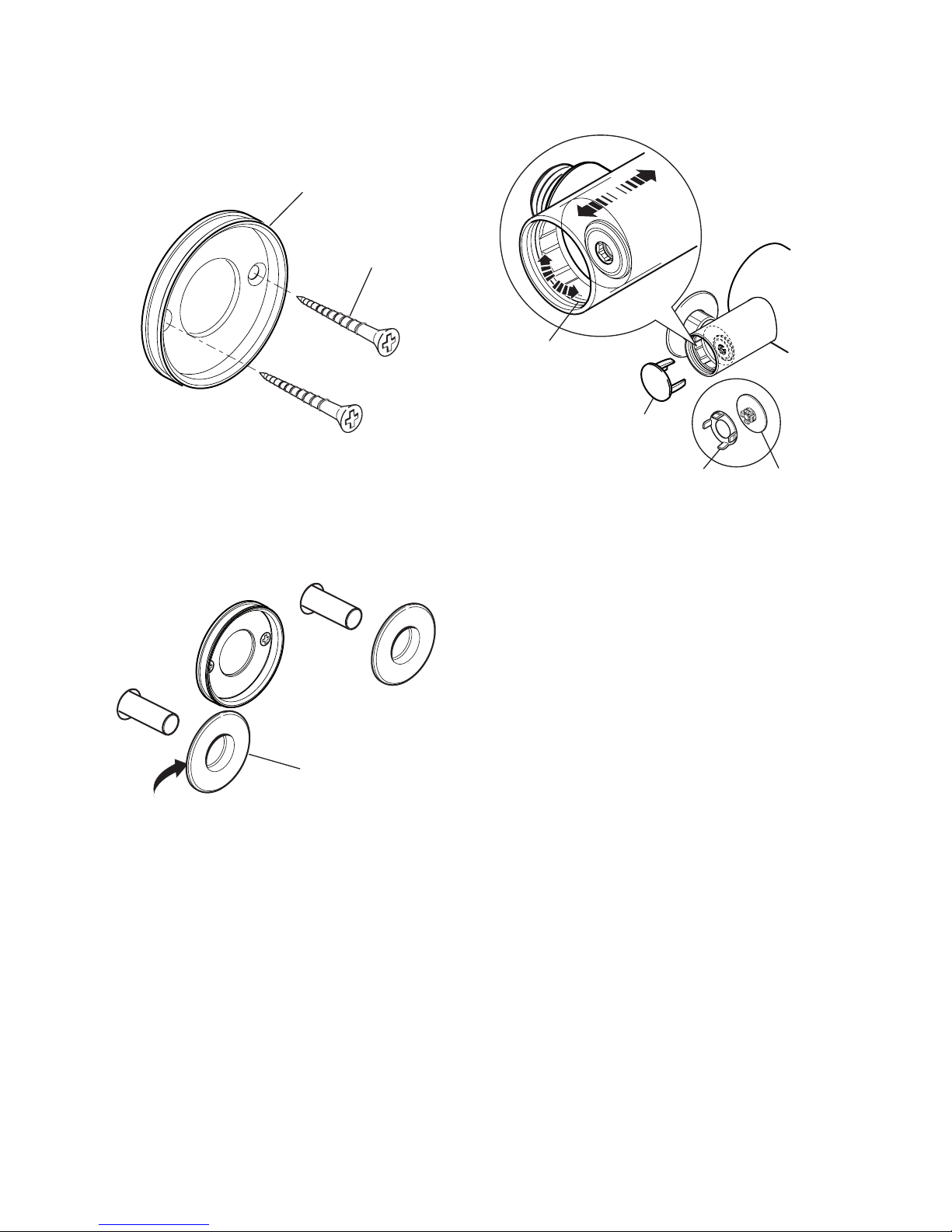
6. remove the backplate from the mixer by
loosening the grubscrew with a 2.5 mm
hexagonal key.
7.
Secure the backplate to the wall using the
screws.
Screw
Backplate
8. For Rear Entry Supplies Only:
a) Fit the concealing plates over the inlet
pipes.
Note! apply silicone sealant to the back
face of the ange.
apply Silicone Sealant
concealing Plate
9. Caution! It is essential at this point
that the supply pipework is thoroughly
ushedthroughbeforeconnectiontothe
mixer. Failure to do so may result in product
malfunction and will not be covered under the
guarantee.
10.
Fit the compression nuts and olives onto the
pipework.
11.
align the mixer with the pipework and fit
onto the backplate. Minor misalignment of
the pipework can be accommodated by the
inlets, which are adjustable between 139 and
153 mm centres.
Important! Make sure that the hot and cold
inlets on the mixer correspond with the hot and
cold inlet supplies.
12. Using a suitable tool, tighten the waterway
securing ring until it abuts the adjustable inlet
preventing outward movement.
concealing cap
(assembled)
Waterway
Securing ring
Securing
clip
concealing
cap
13. assemble the concealing caps and securing
clips and push into the elbow.
14.
tighten the compression nuts onto the mixer
with a suitable spanner.
Caution! take care not to damage the chrome
surfaces.
15.
tighten the grubscrew to secure the mixer to
the backplate.
Page 10
10
16. Fit the shower ttings, refer to your shower
fittings installation and user guide for
instructions.
Note! For high pressure systems (above
0.5 bar) make sure that the ow regulator
(supplied) is tted inside the outlet nipple (refer
to illustration).
Important! The tting of this ow regulator will
invalidate any tMV2 or tMV3 compliance due
to the minimum ow rate requirements. Do
not t the ow regulator in TMV2 and TMV3
applications.
Flow regulator
17. turn on the hot and cold water supplies and
check for leaks.
18.
Before using the shower, refer to section:
‘Commissioning’.
Built-in Thermostatic Mixers
Solid Wall or Stud Partition Fixing
using Rear Mountings
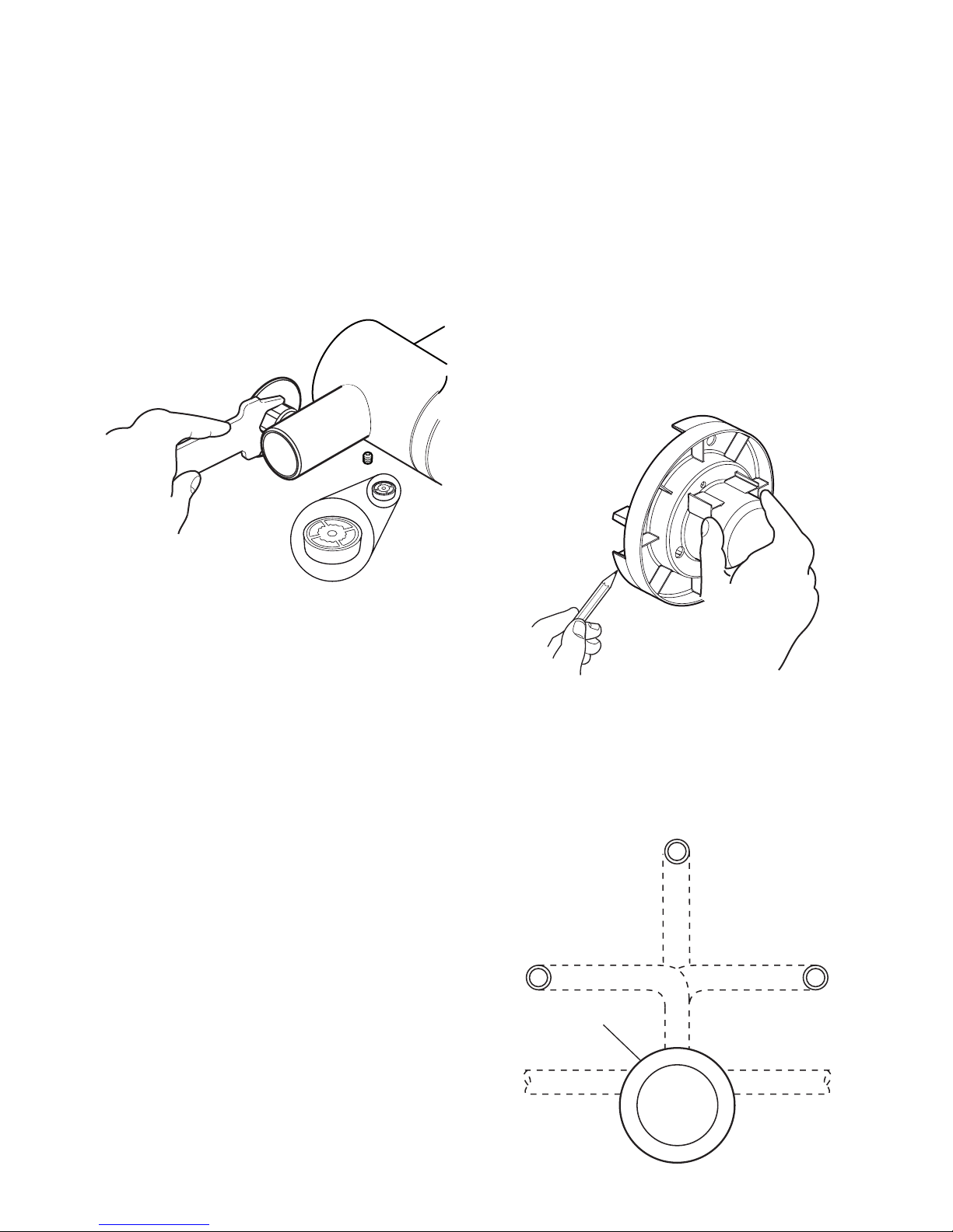
1. determine the route for the hot and cold
supply pipework and for the outlet pipework.
When connecting to BiV Shower Fittings it is
recommended that the outlet be positioned
above and to one side of the mixer. this is to
prevent the exible hose from obstructing the
shower controls.
2.
remove the two shroud screws (retain for later
use) and remove the building-in shroud from
the mixer.
3.
determine the position of the mixer and draw
around the building-in shroud.
4. Mark the routes for the hot and cold supply
pipework (Hot - Left, Cold - Right) and for
the outlet pipework.
Note! (if applicable) The outlet elbow should
be sited above the mixer and on the right or
left, as site dictates.
outlet Pipe Bir
outlet Pipe BiV outlet Pipe BiV
cold inlethot inlet
thermostatic
Mixer
alternative Pipe
layouts
Page 11
11
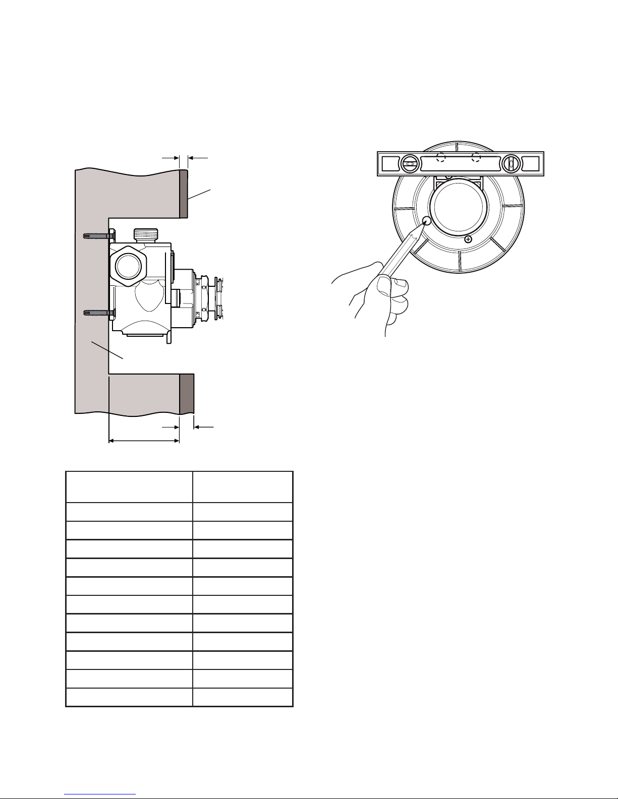
5. cut away the plasterboard and/or brick work
to the required depth.
Important! this depth ‘x’ will depend on the
nished wall thickness e.g. tiles or facia board.
refer to the table for this measurement.
For stud partitions depth ‘x’ refers to the
distance from the rear mounting e.g. timber
noggin, to the front of the wall (before tiling).
Finished Wall
Surface
Finished Wall
thickness
depth ‘x’
rear Mounting (Solid
Wall or Timber Noggin)
Finished Wall thickness
(e.g. tile and adhesive)
Wall cutout depth
‘x’
4 mm 81 - 63 mm
6 mm 79 - 61 mm
8 mm 77 - 59 mm
10 mm 75 - 57 mm
12 mm 73 - 55 mm
14 mm 71 - 55 mm
16 mm 69 - 55 mm
18 mm 67 - 55 mm
20 mm 65 - 55 mm
22 mm 63 - 55 mm
24 mm 61 - 55 mm
6. Ret the building-in shroud to the mixer using
the two shroud screws removed earlier.
7.
Make sure that the mixer is level and central
in the hole, and square to the nished wall
surface (or the control components will not t
correctly), then mark the positions of two xing
screw holes on the wall.
8. For solid walls drill two 6 mm holes for the wall
plugs.
9.
Fit the hot and cold supply pipework (Hot -
Left, Cold - Right).
10.
Caution! It is essential at this point
that the supply pipework is thoroughly
ushedthroughbeforeconnectiontothe
mixer. Failure to do so may result in product
malfunction and will not be covered under the
guarantee.
Page 12
12
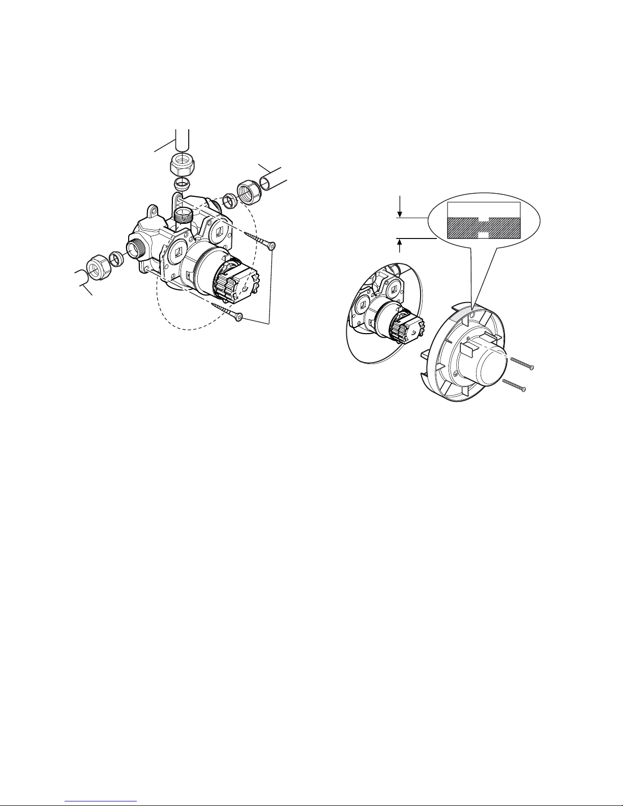
11. insert the wall plugs and attach the mixer to
the wall with the screws provided.
Note! For stud partition installations alternative
xings may be required (not supplied) to x the
mixer to the rear face of the wall cavity or to a
timber noggin.
Screws
outlet Pipe to
Fittings
hot Supply
cold Supply
12. remove the two shroud screws (retain for later
use) and remove the building-in shroud from
the mixer.
13.
Make sure that the olives are tted, connect
the hot and cold supply pipes and tighten the
compression nuts.
14. connect the outlet pipework and install the
rac assembly or Bir assembly, before
continuing with the installation of the mixing
valve.
RAC assembly, go to section: ‘installation,
RAC Assembly’.
BIR assembly, refer to your shower ttings
installation and user guide then continue with
instruction 15.
15.
turn on the water supplies and check for
leaks.
16.
Ret the building-in shroud to the mixer using
the two shroud screws removed earlier.
17.
Using the ‘Finished Wall indicator’ on the
building-in shroud as a guide, nish the wall,
e.g. tiles.
Caution! Make sure that the nished wall
is within the maximum and minimum limits
and to an even depth (no greater than 2 mm
variation) or the control components will not
t correctly.
Finished Wall
F9802
Min
Max
Minimum
nished wall
surface
Maximum
nished wall
surface
18. remove the two shroud screws (retain for later
use) and remove the building-in shroud.
19. Fit the concealing plate and control assembly,
refer to section: ‘Control Assembly’.
Page 13
13
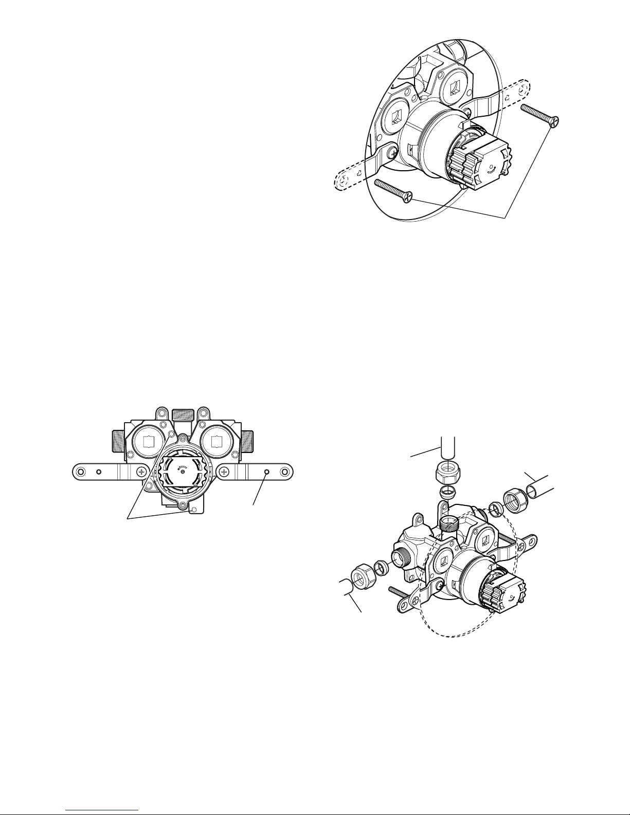
M5 x 40 mm
Fixing Screws
9. Make sure that the olives are tted, connect
the hot and cold supply pipes and tighten the
compression nuts.
10. connect the outlet pipework and install the
rac assembly or Bir assembly, before
continuing with the installation of the mixing
valve.
RAC assembly, go to section: ‘installation,
RAC Assembly’.
BIR assembly, refer to your shower ttings
installation and user guide then continue with
instruction 11.
hot Supply
cold Supply
outlet Pipe
to Fittings
11. turn on the water supplies and check for
leaks.
12.
Fit the concealing plate and control assembly,
refer to section: ‘Control Assembly’.
Panel Fixing using Securing
Brackets
Note! For laminated panels the mixer must be
positioned from the rear of the panel.
Panel thickness must be between 4 and 12 mm
(if a thicker panel is used, it will be necessary
to recess the securing brackets into the rear of
the panel).
Important! Make sure that there is a minimum
clearance of 64 mm behind the laminated panel
to house the mixer.
1. refer to section: ‘Rear Fixing into Solid Walls
or Stud Partitions’ and follow instructions
1 to 4.
2. carefully cut out the laminated panel.
3. Fit the securing brackets to the mixer.
Important! Make sure that the correct holes
are used, otherwise the backplate cannot be
tted.
4.
Position the mixer on the front of the panel,
make sure that it is level and central in the
hole, then mark the position of the M5 xing
holes.
Important! Make sure that the correct holes
are used (refer to illustration).
Backplate
Securing holes
M5 Fixing hole
5. drill the two 5.5 mm holes for the fixing
positions (countersink the holes at the front).
6. Fit the hot and cold supply pipework (Hot Left, Cold - Right).
7. Caution! It is essential at this point
that the supply pipework is thoroughly
ushedthroughbeforeconnectiontothe
mixer. Failure to do so may result in product
malfunction and will not be covered under the
guarantee.
8.
Secure the mixer with the M5 x 40 screws as
shown.
Page 14
14
Solid Wall or Stud Partition Fixing
using Securing Brackets
1. refer to section: ‘Rear Fixing into Solid Walls
or Stud Partitions’ and follow instructions
1 to 4.
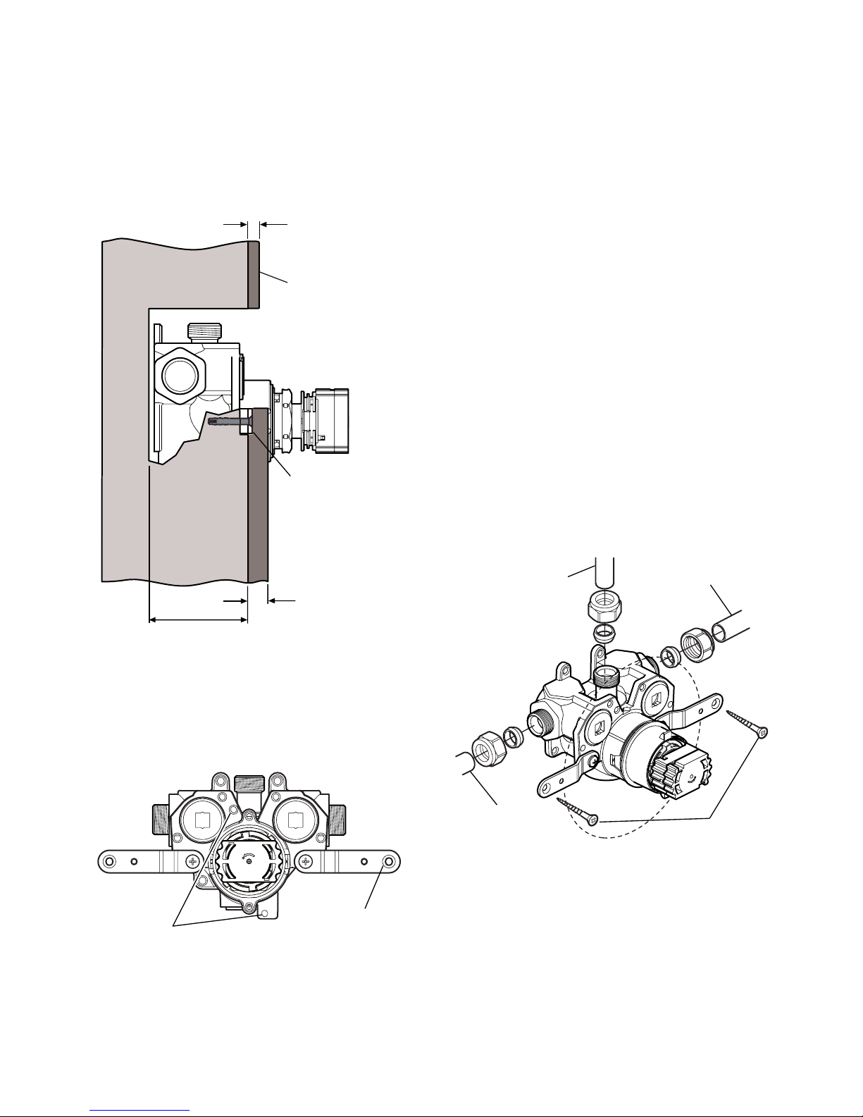
2. remove the plasterboard and/or brick work to
a minimum depth of 62 mm.
62 mm Min
24 mm Max
Finished Wall
4 mm Min
Finished Wall
Finished Wall
Surface
Securing
Bracket
3. Fit the securing brackets to the mixer with the
bracket securing screws.
Important! Make sure that the correct holes
are used, otherwise the backplate cannot be
tted.
Backplate
Securing holes
countersunk
Fixing hole
4. Make sure that the mixer is level and mark the
positions for the countersunk xing holes on
the wall.
5.
For solid walls drill two 6 mm holes for the wall
plugs.
6. Fit the hot and cold supply pipework (Hot -
Left, Cold - Right).
7. Caution! It is essential at this point
that the supply pipework is thoroughly
ushedthroughbeforeconnectiontothe
mixer. Failure to do so may result in product
malfunction and will not be covered under the
guarantee.
8.
remove the wall brackets from the mixer.
9. Make sure that the olives are tted, connect
the hot and cold supply pipes and tighten the
compression nuts.
10.
Ret the wall brackets to the mixer, t the wall
plugs and x the mixer to the wall with the
screws provided.
Note! For stud partition installations alternative
xings may be required (not supplied).
14. connect the outlet pipework and install the
rac assembly or Bir assembly, before
continuing with the installation of the mixing
valve.
RAC assembly, go to section: ‘installation,
RAC Assembly’.
BIR assembly, refer to your shower ttings
installation and user guide then continue with
instruction 12.
Screws
outlet Pipe
to Fittings
hot Supply
cold Supply
12. turn on the water supplies and check for
leaks
Page 15
15
13. Ret the building-in shroud to the mixer using
the two shroud screws removed earlier.
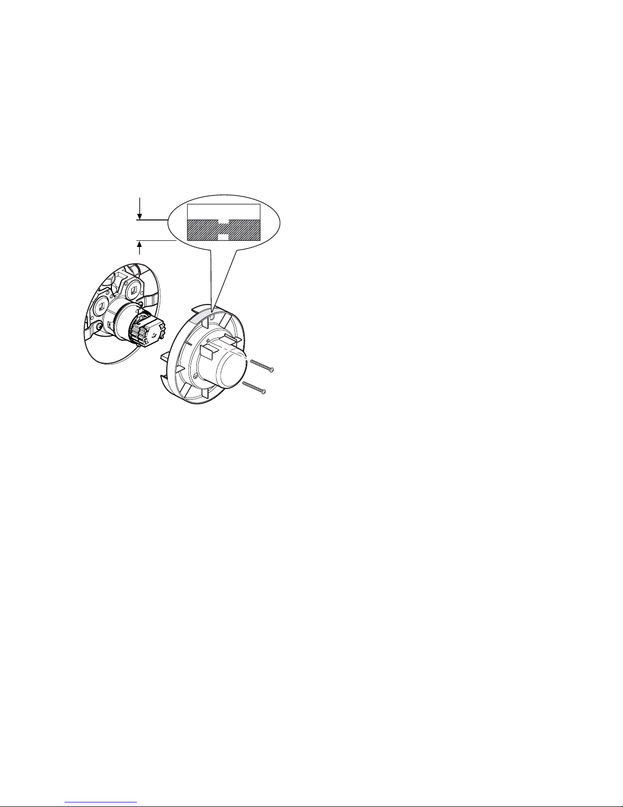
14.
Using the ‘Finished Wall indicator’ on the
building-in shroud as a guide, nish the wall,
e.g. tiles.
Caution! Make sure that the nished wall
is within the maximum and minimum limits
and to an even depth (no greater than 2 mm
variation) or the control components will not t
correctly.
Finished Wall
F9802
Min
Max
Minimum
nished wall
surface
Maximum
nished wall
surface
15. remove the two shroud screws (retain for later
use) and remove the building-in shroud.
16. Fit the concealing plate and control assembly,
refer to section: ‘Control Assembly’.
Page 16
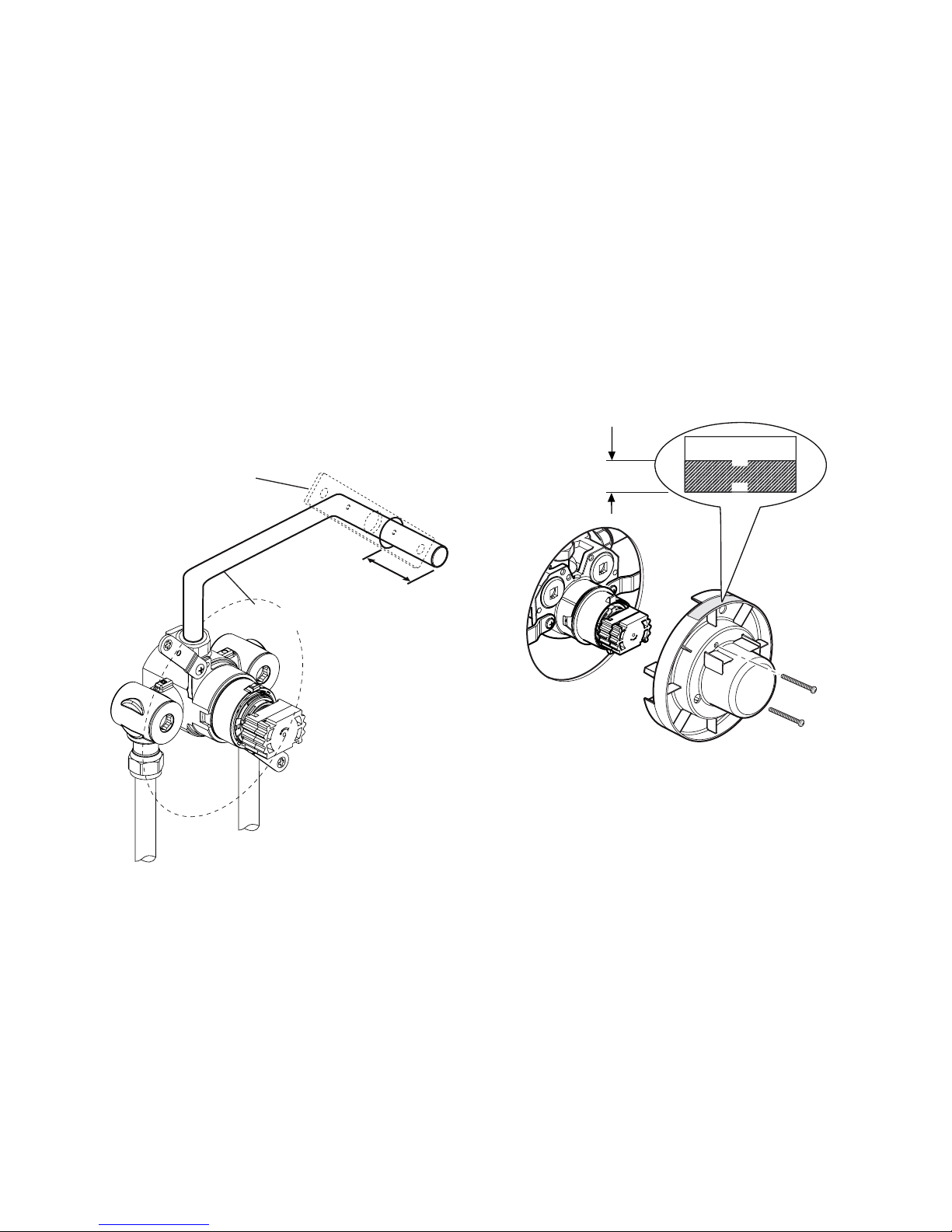
16
RAC Assembly
1. Before the RAC assembly can be tted you
must have rst installed your built-in shower
control and have connected the inlet and outlet
pipework.
Important! Make sure that the outlet pipework
protrudes through a Ø25 mm hole in the wall
or stud partition by approximately 40 mm.
Note! For stud partition installations where
access to the rear of the partition is possible,
t the RAC wallplate over the outlet pipework
on the inside of the partition.
For stud partition installations where access
to the rear of the wall is not possible, follow
instructions for solid wall installations, making
sure that suitable wall xings (not supplied) are
used to secure the wallplate to the outside of
the stud partition.
40 mm
rac Wallplate
(shown tted for rear
access stud partitions only)
outlet Pipe to Fittings
2. temporarily cap off the outlet pipe, turn on the
water supplies and check for leaks.
3. Determine the nished wall position (e.g. tile
thickness). Turn off the water supply, carefully
uncap the outlet pipe and cut to length, the
outlet pipe must protrude through the nished
wall surface by 21–23 mm.
Note! remove any burrs from the pipes before
proceeding.
4. For solid wall installations or stud partition
installations without rear access go to
instruction 11.
For stud partition installations with access
to the rear of the partition continue with
instruction 5.
5.
Secure the building-in shroud to the mixing
valve using the two building-in shroud screws
removed earlier.
6.
Using the building-in shroud as a guide, nish
the wall, e.g. tiles.
Caution! Make sure that the nished wall
is within the maximum and minimum limits
and to an even depth (no greater than 2 mm
variation) or the control components will not t
correctly.
Finished Wall
F9802
Min
Max
Minimum
nished wall
surface
Maximum
nished wall
surface
7. remove the two building-in shroud screws
(retain for later use) and remove the building-in
shroud.
8. Place the rac backplate over the outlet pipe
with the arrow pointing up. the screw holes
should be at 45° to the horizontal.
Page 17
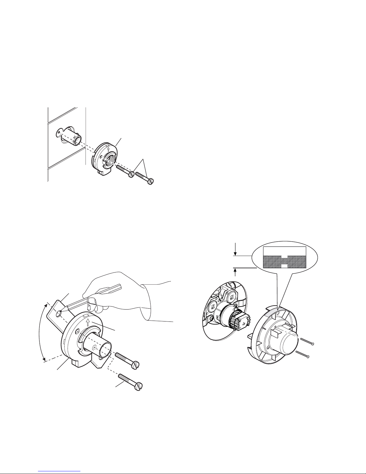
17
9. Mark the positions of the two rac backplate
xing holes and drill two Ø5.5 mm holes.
Caution! Make sure that you do not drill into
pipework in the wall.
10. hold the rac wallplate in position on the
rear of the partition, insert the two backplate
screws and secure the rac backplate to the
wallplate. Make sure that the foam seal abuts
the nished wall surface. Go to instruction
22.
rac Backplate
Backplate
Screws
11. loosely attach the rac backplate to the rac
wallplate, using the two backplate screws
provided.
12.
Place the rac backplate/wallplate assembly
over the outlet pipe with the arrow pointing
vertically up. the screw holes should be at
40° to the horizontal.
13.
Mark the positions of the two rac wallplate
xing holes.
Wallplate
rac Backplate
Backplate Screws
arrow
40°
14. remove the assembly from the wall and
separate the backplate from the wallplate.
15. For solid walls drill two Ø6 mm holes for the
wall plugs. For other types of wall structure
alternative fixings may be required (not
supplied). If necessary, make a recess 6 mm
deep to accept the wallplate for ush tting of
the outlet to the wall surface.
Caution! Make sure that you do not drill into
pipework in the wall.
16. Fit the two wall plugs supplied and secure
the wallplate to the wall with the two wallplate
screws.
17. Make sure that there is clearance behind the
wallplate and temporarily t the two backplate
screws into the wallplate. this will prevent
the xing holes from becoming blocked with
plaster or grout.
18.
Secure the building-in shroud to the mixing
valve using the two shroud screws removed
earlier.
19.
Using the building-in shroud as a guide, nish
the wall, e.g. tiles.
Caution! Make sure that the nished wall
is within the maximum and minimum limits
and to an even depth (no greater than 2 mm
variation) or the control components will not t
correctly.
Finished Wall
F9802
Min
Max
Minimum
nished wall
surface
Maximum
nished wall
surface
20. remove the two backplate screws, the two
building-in shroud screws (retain for later use)
and the building-in shroud.
21. Place the backplate over the outlet pipe with
the arrow pointing vertically up and tighten the
two backplate screws. Make sure that the foam
seal abuts the nished wall surface.
Page 18
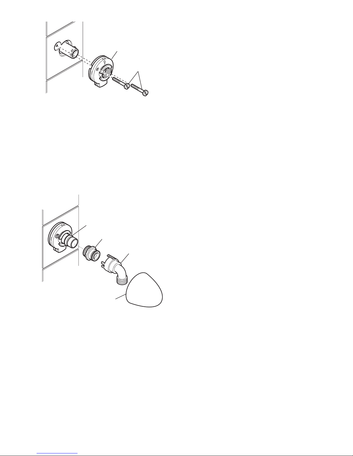
18
rac Backplate
Backplate
Screws
22. Check that the blue ‘O’ seal is tted inside the
backplate nut. Fit the olive and the backplate
nut over the outlet pipe and tighten the nut.
23. Check that the second ‘O’ seal (black) is tted
to the outside of the backplate nut. Press
the elbow onto the backplate, make sure
that the clips on the elbow engage with the
backplate.
24. Press the shroud over the elbow, make
sure that it engages with the lugs on the
backplate.
Backplate nut
olive
elbow
Shroud
25. this completes the installation of the rac
assembly, fit the concealing plate and
control assembly. refer to section: ‘Control
Assembly’.
Page 19
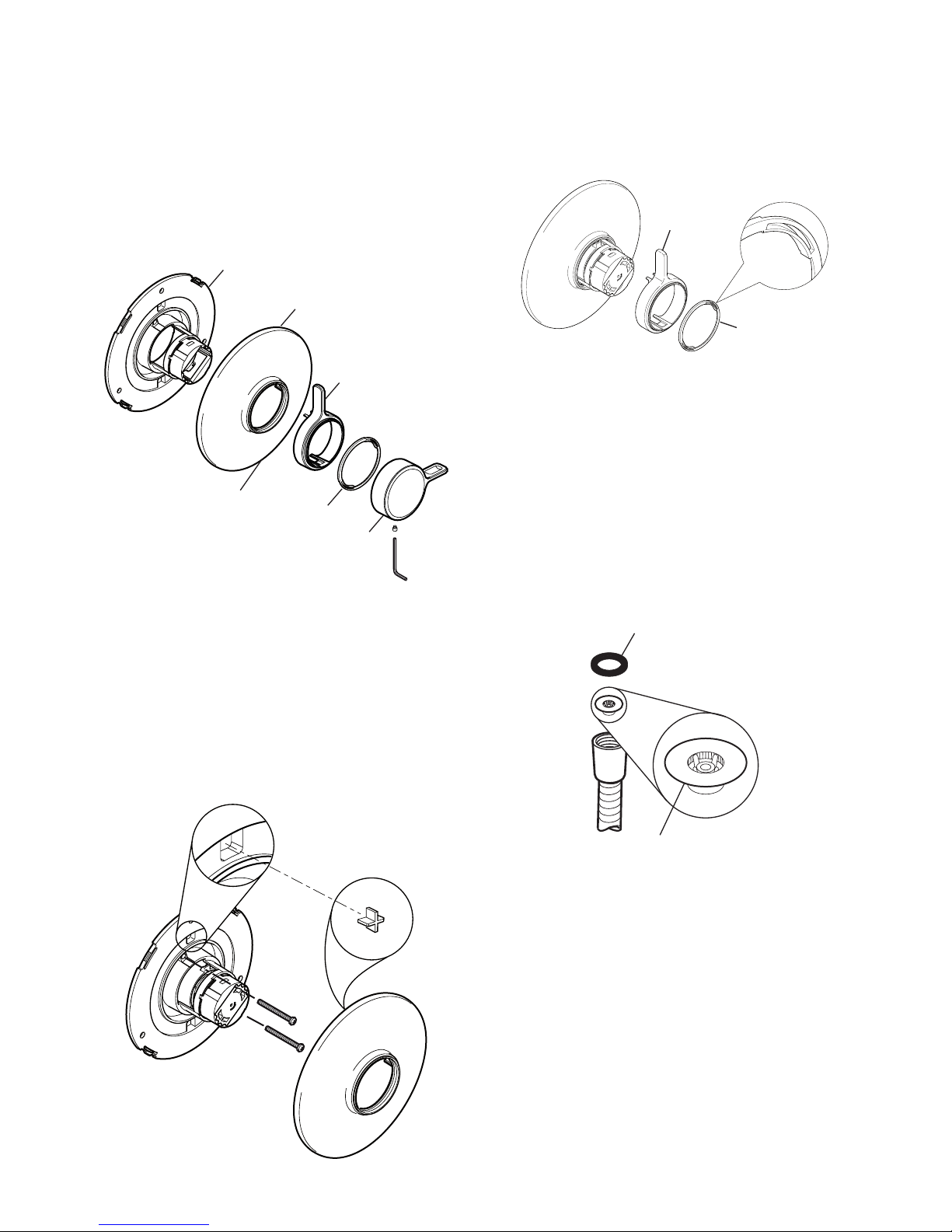
19
Control Assembly
1. Unscrew the grubscrew and pull off the
temperature control knob, bearing and ow
control lever.
2.
carefully unclip the concealing plate from the
backplate.
Note! Use a screwdriver in the cutout to assist
separation.
Backplate
Flow control
lever
temperature
control Knob
concealing Plate
Bearing
cutout
3. attach the backplate using the two shroud
screws removed earlier. tighten the screws
until the foam seal is compressed against the
nished wall. Do not overtighten.
4.
With the cutout at the bottom, locate the
concealing plate over the mixer, engage the
crosses in the concealing plate with the square
recesses in the backplate, and push rmly until
the concealing plate clicks into position.
5. Locate the ow control lever over the control
assembly and push rmly into place.
6. Fit the bearing onto the ow lever.
Note! align the bearing with the cutouts on the
control assembly.
Flow control
lever
Bearing
7. Fit the shower ttings, refer to your shower
ttings installation and user guide.
Note! For high pressure systems (above
0.5 bar) make sure that the ow regulator
(supplied) is tted under the hose washer
(refer to illustration).
Important! The tting of this ow regulator will
invalidate any tMV2 or tMV3 compliance due
to the minimum ow rate requirements. Do
not t the ow regulator in TMV2 and TMV3
applications.
Flow regulator
hose Washer
8. turn on the hot and cold water supplies and
check for leaks.
9.
Before using the shower, refer to section:
‘Commissioning’.
Page 20
20
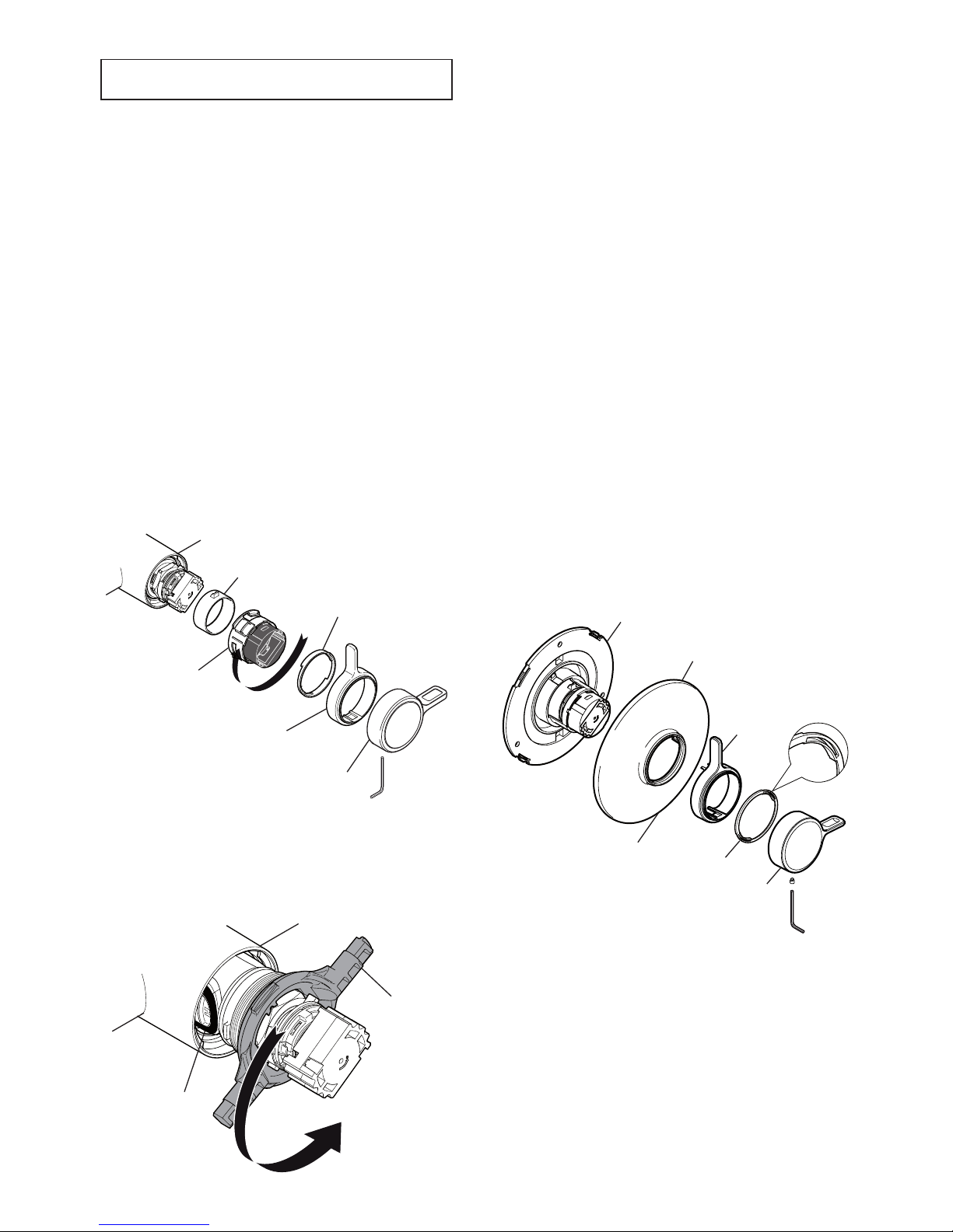
reVerSed inlet SUPPlieS
the Mira Select Flex thermostatic mixer is
supplied with inlet connections Hot - Left, Cold
- Right and Outlet - Bottom (exposed models),
Outlet - Top (built-in models) as standard. If
the hot and cold water supply pipes have been
reversed during installation, the thermostatic
cartridge must be removed and rotated 180°.
Exposed Models
1.
isolate the hot and cold water supplies and
operate the flow control lever to relieve
pressure and drain any residual water.
2.
Unscrew the grubscrew with a 2.5 mm
hexagonal key and pull off the temperature
control and ow control levers.
3.
Pull off the bearing.
4. rotate the white section of the control lever
interface 90° clockwise and pull off.
5.
Pull off the ow lever adaptor.
Bearing
temperature
control lever
Flow control
lever
Flow lever
adaptor
control lever
interface
6. Locate the ‘O’ key (supplied) onto the cartridge
nut and turn anticlockwise. Unscrew fully and
pull the cartridge from the mixer body.
7. rotate the cartridge 180°.
‘o’ Key
cartridge Seal
8. Make sure that the two inlet seals are tted
and carefully push the cartridge back into the
mixer body, aligning the lugs into the slots.
Note! check that the cartridge lug stamped
‘h’ is aligned with the hot inlet supply.
Important! take care when fitting the
cartridge. damage to the cartridge inlet seals
may result in dripping from the showerhead.
9.
tighten the nut by turning the ‘o’ key
clockwise.
10.
refit the controls in reverse order.
Before using the shower, refer to section:
‘Commissioning’.
Built-in Models
1.
isolate the hot and cold water supplies and
operate the flow control lever to relieve
pressure and drain any residual water.
2.
Unscrew the grubscrew and pull off the
temperature control lever, bearing and ow
control lever.
3.
carefully unclip the concealing plate from the
backplate.
Note! Use a screwdriver in the cutout to assist
separation.
Backplate
Flow control
lever
temperature
control Knob
concealing Plate
Bearing
cutout
Page 21
21
oPeration
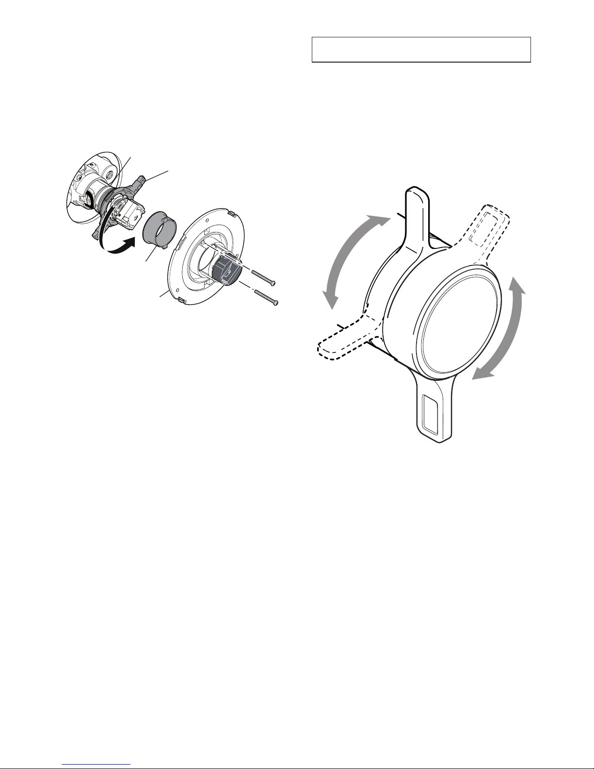
the Mira Select Flex is a thermostatic mixer
with separate control levers for on/off and
temperature.
OFF
turn the temperature control
lever clockwise to decrease
the temperat ure and
anticlockwise to the preset
maximum temperature
turn the Flow control
lever anticlockwise to
the preset maximum ow
ON
Warmer
Cooler
4. Unscrew the two backplate screws and remove
the backplate.
5.
Pull off the red ow lever adaptor.
6. Locate the ‘O’ Key (supplied) onto the cartridge
nut and turn anticlockwise. Unscrew fully and
pull the thermostatic cartridge from the mixing
valve.
thermostatic
cartridge
‘o’ Key
Flow lever adaptor
Backplate
7. rotate the thermostatic cartridge 180°.
8. Make sure that the two inlet seals are tted
and carefully push the thermostatic cartridge
back into the mixing valve, aligning the lugs
into the slots.
Note! check that the cartridge lug stamped
‘h’ is aligned with the hot inlet supply.
Important! take care when fitting the
thermostatic cartridge. damage to the cartridge
inlet seals may result in dripping from the
showerhead.
9.
tighten the nut by turning the ‘o’ key
clockwise.
10.
Ret the controls in reverse order.
Note! When retting the bearing, make sure
that the cutouts are aligned with the control
assembly.
11.
Before using the shower, refer to section:
‘Commissioning’.
Page 22
22
coMMiSSioninG
commissioning must be carried out in accordance
with these instructions, and must be conducted by
designated, qualied and competent personnel.
Exercising the Thermostat
thermostatic mixing valves with wax thermostats
are inclined to lose their responsiveness if not
used. Valves which have been in storage, installed
but not commissioned, or simply not used for
some time should be exercised before setting the
maximum temperature or carrying out any tests.
a simple way to provide this exercise is:
(a) Make sure that the hot and cold water
are available at the valve inlets, and the
outlet is open.
(b) Move the temperature control rapidly from
cold to hot and hot back to cold several
times, pausing at each extreme.
Maximum Temperature
Note! For type 2 and type 3 valves in healthcare
installations the maximum blend temperature is
determined by the application, refer to section:
‘Type 2 and Type 3 Valves, Application’.
the maximum blend temperature obtainable by
the user should be limited, to prevent accidental
selection of a temperature that is too hot.
all Mira thermostatic mixing valves are fully
performance tested and the maximum temperature
is preset to approximately 41°c under ideal
installation conditions at the factory.
Site conditions and personal preference may
dictate that the maximum temperature has to be
reset following installation.
temperatures should always be recorded using
a thermometer with proven accuracy.
Maximum Temperature Setting
Before using the shower, the maximum
temperature level must be checked to make sure
that it is safe. it has been preset to approximately
41°c at the factory, but due to variations in site
conditions the maximum temperature may need
adjustment.
Note! Make sure that the hot water temperature
is at least 55°C and that there is a sufcient
supply.
1. turn on the shower to maximum flow
and temperature (i.e. both controls fully
anticlockwise) and allow the temperature to
stabilise.
if the temperature is too hot or too cold adjust
as follows:
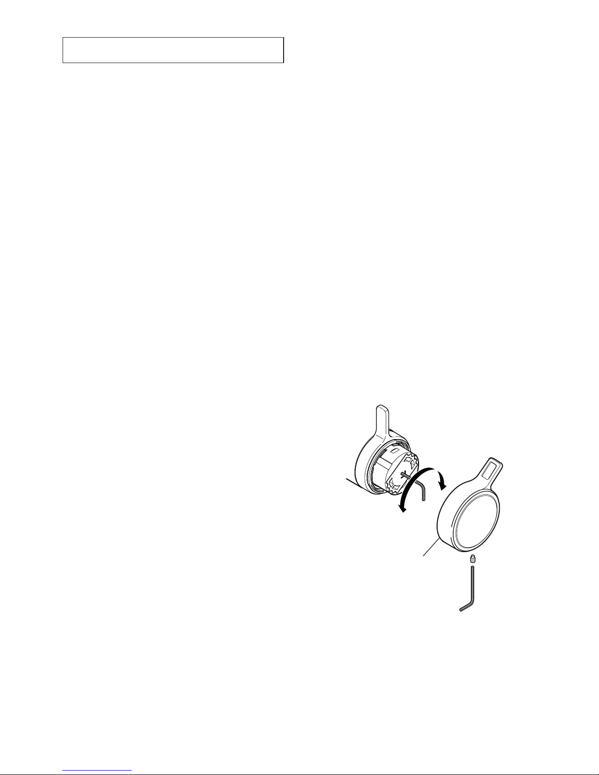
2.
Using a 2.5 mm Hexagon Key (supplied),
unscrew and remove the temperature control
lever.
3. insert the 2.5 mm hexagon Key into the centre
of the Green hub and engage with the hidden
temperature adjust Screw.
4. turn the hexagon Key until the required
maximum showering temperature is obtained.
turn anticlockwise to increase or clockwise
to decrease the temperature (¼ turn =
approximately 1°C).
temperature
control lever
5. once the desired maximum blend temperature
has been achieved, turn off the shower.
6.
Ret the Temperature Control Lever.
7. check that the showering temperature is
correct.
Page 23

23
tyPe 2 and tyPe 3 ValVeS
Application
the approved designations for Type 2 Valves
are as follows:
Models designation
Mira Select Flex hP-S, lP-S
the permitted application details are:
designation
operating
Pressure
range
application
Mixed
Water
temp
†
hP-S
high
Pressure
Shower
41°c
Max
lP-S
low
Pressure
Shower
41°c
Max
the approved designations for Type 3 Valves
are as follows:
Models designation
Mira Select Flex hP-S, lP-S
the permitted application details are:
designation
operating
Pressure
range
application
Mixed
Water
temp
†
hP-S
high
Pressure
Shower
41°c
Max
lP-S
low
Pressure
Shower
41°c
Max
†
Mixed water temperature at discharge point.
Important! For tMV2 installations the mixed
water temperature at the discharge point should
never exceed 46°c.
Note! For washbasins, it is assumed that you are
washing under running water.
Note! Bath ll temperatures of more than 44°C
should only be available when the bather is always
under the supervision of a competent person (e.g.
nurse or care assistant).
in order to achieve the safe water temperatures
expected of type 2 and type 3 Valves it is
essential that the valve is used only for the
applications covered by its approved designations,
with the appropriate water supply pressures
and temperatures, and it is commissioned,
maintained and serviced in accordance with
the recommendations contained in this guide
(refer to the section ‘Maintenance, In-Service
Tests’ for in service test frequency that must be
used as a minimum guide in type 2 and type 3
installations).
Supply Conditions
For applications where a type 2 or type 3 Valve
is required, the supply conditions must comply
with the values extracted from the tMV2 and
TMV3 standard (EN1287 & EN1111), shown in the
table below. note that both hot and cold supply
pressures must lie within the same pressure
range.
operating Pressure
range
high
Pressure
low
Pressure
Maximum Static
Pressure (bar)
10 10
Maintained Pressure,
Hot and Cold (bar)
1 to 5 0.2 to 1
hot Supply
Temperature (°C)
55 to 65 55 to 65
cold Supply
Temperature (°C)
≤25 ≤25
Valves operating outside these conditions cannot
be guaranteed to operate as type 2 or type 3
Valves.
Commissioning
(temperatures should always be recorded with a
thermometer with proven accuracy)
1. check that the designation of the thermostatic
mixing valve matches the intended
application.
2. check that the supply pressures are within
the range of operating pressures for the
designation of the thermostatic mixing valve.
3.
check that the supply temperatures are within
the range permitted for the shower control and
by guidance information on the prevention of
legionella etc.
4.
check inlet pipework temperatures for correct
function of the non return valves.
Page 24

24
5. all connections and thermostatic mixing valve
body are watertight.
6.
operate the outlet flow divertor lever and
check:
(a)
Flow rate is sufcient for purpose (low
pressure supplies may require removal
of ow regulators).
(b) Te m p e r a t u r e ( s ) o b t a i n e d a r e
acceptable.
7. exercise the thermostat (refer to section:
‘Commissioning, Exercising the
Thermostat’).
8.
adjust the temperature of the mixed water in
accordance with the instructions in this manual
and the requirement of the application and
then carry out the following sequence:
(a)
record the temperature, and pressures
if possible, of the hot and cold water
supplies.
(b) Record the temperature and ow rate of
the mixed water at the largest draw-off
ow rate.
(c) Record the temperature and ow rate of
the mixed water at a smaller draw-off ow
rate.
(d) isolate the cold water supply to the
mixing valve and monitor the mixed water
temperature.
(e) record the maximum temperature
achieved as a result of d. and the nal
temperature.
Note! The nal mixed water temperature
should not exceed the values shown in
the table below. any higher temperatures
should only occur briey.
(f) record the date, equipment, thermometer
etc. used for the measurements.
application
Maximum Mixed
Water temperature
Bidet 40°c
Shower 43°c
Washbasin 43°c
Bath (44°C ll) 46°c
Bath (46°C ll) 48°c
Maintenance
Planned maintenance for type 3 Valves must
use the ‘in-Service test’, at the frequency given
in the guide to in-service test frequency, and
should employ temperature testing, performance
log books and training as detailed in section:
‘Maintenance’.
type 2 valves must use the ‘in-Service test’ at a
frequency of not more than one year.
Page 25

25
Maintenance
General
the Mira Select Flex thermostatic mixing valve
is designed to need only minimal maintenance
in normal use. the only serviceable parts are the
inlet lters which should be checked and cleaned
every 12 months. if a malfunction occurs with the
thermostatic cartridge then this will necessitate a
complete cartridge replacement.
Note! the cartridge contains no internally
serviceable parts.
if you require a Mira trained engineer or agent,
refer to section: ‘Customer Service’.
Lubricants
Silicone based lubricants must only be used on
the rubber seals.
Caution!
oil based or other lubricant types may
cause rapid deterioration of seals.
Cleaning
the chrome plated parts should be cleaned using
a mild washing up detergent or soap solution,
rinsed and then wiped dry with a soft cloth.
Warning! Many household cleaners contain
abrasive and chemical substances, and should not
be used for cleaning plated or plastic ttings.
Do not use descalents on this product.
In-service Tests
the principal means for determining the continuing
satisfactory performance of the mixing valve is the
in-service test.
Follow the procedure detailed in the ow diagram
“in-service test Procedure”.
Planned Maintenance
Malfunction of thermostatic mixing valves is
almost always progressive in nature and will
be detected by the use of proper temperature
checking and maintenance routines.
We recommend a preventative maintenance
procedure based on site conditions and the risk
to the user. all results must be recorded in a log
book.
Healthcare
healthcare applications are hospitals, aged
person facilities, residential care homes, etc. and
any other application where the user is similarly
at risk.
Ultimately, the user or attendant must exercise
diligence to make sure that the delivery of warm
water is at a stable, safe temperature. this is
particularly important in healthcare procedures,
such as supervised bathing where patients
are unable to respond immediately to unsafe
temperatures.
irrespective of supply and usage conditions or the
evidence of in-service tests, critical components
should be replaced at intervals of no more than
5 years.
Note! during the replacement of critical
components, it may be necessary to replace
other non-critical components.
Page 26
26
Frequency of In-service Tests
Healthcare
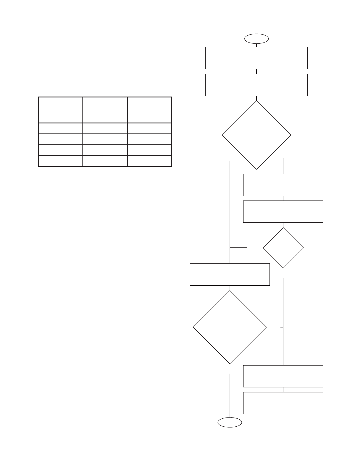
Follow the procedure detailed in the ow diagram
“in-service test Procedure”. this procedure must
be followed 6 to 8 weeks after commissioning
and 12 to 15 weeks after commissioning. the
recorded blend temperature
(Tb)
from these two
tests will determine the maximum frequency for
future service intervals.
result of 6-8
week tests
result of
12-15 week
tests
next service
interval
< 1°c < 1°c 9 - 12 weeks
> 1°c < 1°c 9 - 12 weeks
< 1°c > 1°c 9 - 12 weeks
> 1°c > 1°c 6 - 9 weeks
the subsequent in-service test results should be
used as a guide, in conjunction with a suitable risk
assessment, to determine the schedule of future
in-service tests.
More regular temperature checks should be
made where increased risks are perceived, i.e.
patients are unable to immediately respond to an
increase in water temperature, by either shutting
the water off or removing themselves from contact
with the water.
Maintenance personnel should also make sure
that the staff are aware of the importance of
reporting temperature variations and when
detected, these should be recorded in the log
Book.
Commercial
check for correct blend setting every 6 months.
Follow the procedure detailed in the ow diagram
“in-service test Procedure”, every 12 months.
Start
Measure and record supply
temperature and pressures. Make sure
that they are within valve specications.
Measure and record blend
temperature
(Tb)
and ow rate.
Has ow rate fallen
signicantly or fallen
below minimum ow
specication?
check and clean non return
valve, strainers and outlet.
Measure and record blend
temperature
(Tb)
and ow rate.
Has ow rate
improved?
carry out a performance check.
refer to the commissioning
procedure.
yes
no
yes
has the blend
temperature
changed by more
than 2°c from the
previous recorded
value
(Tb)
?
refer to section: ‘Fault
Diagnosis’.
carry out the commissioning
procedure.
no
yes
Finish
no
Note! all measurements and results should be
recorded in the log Book.
Flow Diagram, In-service Test Program
Page 27

27
Fault Diagnosis
Symptom:
Only hot or cold water from the mixer outlet.
•
Outlet temperature too hot / too cold.•
CauseRectication:
Inlets reversed (hot supply to cold supply). •
Refer to section: ‘Reversed Inlet Supplies’.
No hot water reaching mixer.
•
Check the lters for any blockage.•
Installation conditions outside operating •
parameters, refer to sections: ‘Specications’
and ‘Commissioning’.
—————————————
Symptom:
Fluctuating or reduced ow rate.
•
CauseRectication:
Check the showerhead, hose and lters for •
any blockage.
Make sure that the maintained inlet pressures
•
are nominally balanced and sufcient, refer to
section: ‘Specications’.
Make su r e that th e inlet te m p e r a t u re
•
differentials are sufcient, refer to section:
‘Specications’.
Air lock or partial blockage in the pipework.
•
Flow regulator tted incorrectly.•
—————————————
Symptom:
Water leaking from the showerhead.
•
CauseRectication:
Normal for a short period after shut off.•
Check that the pressures are not in excess of •
the specications for the product.
Renew the thermostatic cartridge.
•
Page 28
28
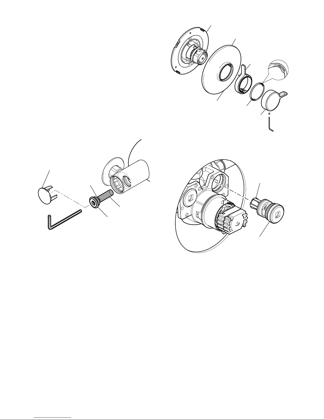
Backplate
Flow control
lever
temperature
control Knob
concealing Plate
Bearing
cutout
4. Unscrew the two shroud screws and remove
the backplate from the mixer.
Filter
Filter assembly
5. Unscrew the lter assembly.
6. The lter assembly can be cleaned or replaced
as necessary.
7. Reassemble the lter assembly and screw into
the mixer body.
8. turn on the hot and cold water supplies and
check for leaks.
9. Ret the controls in reverse order.
Note! When retting the bearing, make sure
that the cutouts are aligned with the control
assembly.
Inlet Filters
The inlet lters should be checked and cleaned
as necessary every 12 months.
Note! The inlet lters must not be removed except
for cleaning. if the thermostatic mixer is operated
without the inlet lters tted the warranty on the
product will be void.
Exposed Models:
1.
isolate the hot and cold water supplies and
operate the ow control lever to drain any
residual water.
2.
carefully remove the concealing caps and
unscrew the lter plugs with a 5 mm hexagonal
wrench. Remove the lters.
concealing cap
Filter Plug
Filter
‘o’ Seal
3. Clean the lters under a jet of water to remove
any lodged particles.
4.
Ret the lters and tighten the lter plugs.
Note! Make sure that the ‘O’ seal is tted
correctly and undamaged.
5.
turn on the hot and cold water supplies and
check for leaks.
6.
Ret the concealing caps.
Built-in Models
1.
isolate the hot and cold water supplies and
operate the ow control lever to drain any
residual water.
2.
loosen the grubscrew to remove the
temperature control knob. then remove the
ow control lever.
3. carefully unclip the concealing plate from the
backplate.
Note! Use a suitable screwdriver in the cutout
to assist separation.
Page 29

29
noteS
Page 30
30
SPare PartS
Note! all spare parts supplied individually unless
stated otherwise.
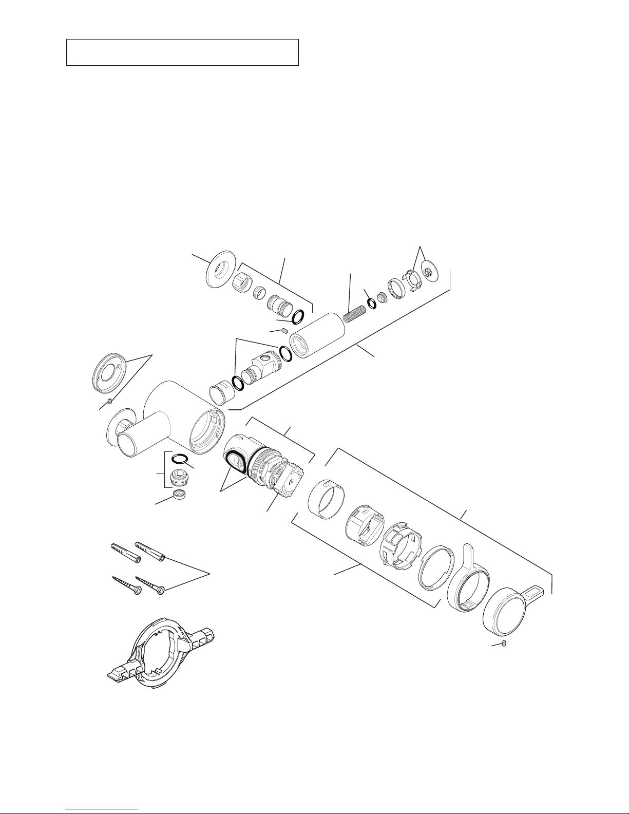
Exposed Models
1595.067 Screw Pack (identied ‘A’)
1679.044 Seal Pack (identied ‘B’)
1062477 (2 off)
Filter Pack
1062479
outlet connector
1663.265
Flow regulator Pack
B
1595.231
‘o’ Key
a
a
1592.081
handle adaptor Pack
1062476
Backplate
1679.041 (2 off)
concealing cap
B
B
1595.036
temperature
hub assembly
B
090.95 (2 off)
Pipe concealing Plate
a
1595.039
thermostatic cartridge
1679.040
handle Pack
1679.043
adjustable inlet
connector
B
a
1679.042 (also includes 1679.043)
elbow assembly
Page 31
31
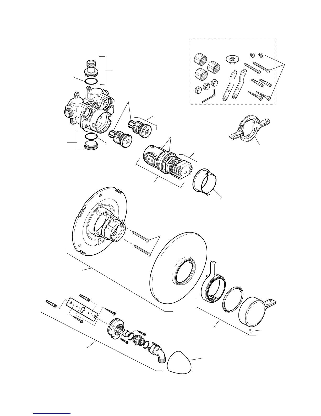
Built-in Models
1679.034 Screw Pack (identied ‘A’)
1679.035 Seal Pack (identied ‘B’)
1679.039
handle Pack
450.22
RAC Shroud (chrome)
450.20
rac Mounting Pack
1592.070
component Pack
1595.231
‘o’ Key
1592.087
concealing Plate
assembly
1595.039
thermostatic cartridge
1595.036
hub Pack
1595.036
Filter Pack (2 off)
1595.037
Filter Assembly (2 off)
1592.086
Flow lever adaptor
1679.038
inlet / outlet
connector Pack
1679.038
inlet / outlet
connector Pack
a
a
a
B
B
B
Page 32

32
cUStoMer SerVice
1088609-W2-B (1679) (B92J/K) © Kohler Mira Limited, June 2008
1
Guarantee of Quality
Mira Showers guarantee your product against any defect
in materials or workmanship, provided that it is installed
and maintained in accordance with the instructions given
in this guide.
Within the guarantee period we will resolve defects, free
of charge, by repairing or replacing parts or modules as
we may choose.
To be free of charge, service work must only be undertaken
by Mira Showers or our approved agents.
Service under this guarantee does not affect the expiry
date of the guarantee.
The guarantee on any exchanged parts or product ends
when the normal product guarantee period expires.
Not covered by this guarantee:
Planned maintenance, or replacement parts required to
comply with the servicing requirements of the TMV 2 and
TMV 3 healthcare schemes (where applicable).
Damage or defects arising from incorrect installation,
improper use or lack of maintenance, including build-up
of limescale.
Damage or defects if the product is taken apart, repaired or
modifi ed by any persons not authorised by Mira Showers
or our approved agents.
This guarantee is in addition to your statutory and other
legal rights.
What to do if something goes wrong
If when you first use your shower, it doesn’t function
correctly, fi rst contact your installer to check that installation
and commissioning are satisfactory and in accordance with
the instructions in this manual. We are on hand to offer you
or your installer any advice you may need.
Should this not resolve the diffi culty, simply contact our
Customer Services Team who will give every assistance
and, if necessary, arrange for our service engineer to
visit. If the performance of your shower declines, consult
this manual to see whether simple home maintenance is
required. Please call our Customer Services Team to talk
the diffi culty through, request a service under guarantee
if applicable, or take advantage of our comprehensive
After-Sales service.
As part of our quality and training programme calls may be
recorded or monitored.
Our Customer Services Team is comprehensively trained to
provide every assistance you may need: help and advice,
spare parts or a service visit.
Spare Parts
We maintain an extensive stock of spares and aim to provide
support throughout the product’s expected life.
Genuine Mira spares can be purchased direct from
Customer Services or from approved stockists or merchants
(locations on request).
Spare parts will normally be despatched within two working
days. Payment can be made using most major Credit or
Debit cards at the time of ordering. Should payment by
cheque be preferred, a pro-forma invoice will be sent.
All spares are guaranteed for 12 months from date of
purchase. Spares that have been supplied directly from us
can be returned within one month from date of purchase,
providing that they are in good order and the packaging
is unopened.
Note! Returned spares will be subject to a 15% restocking
charge and authorisation must be obtained before return.
Please contact our Customer Services Team.
Note! In the interests of safety, spares requiring exposure to
mains voltages must only be fi tted by competent persons.
Service / Repairs
Our Service Force is available to provide a quality service
at a reasonable cost. You will have the assurance of a Mira
trained engineer/agent, genuine Mira spare parts and a
12 month guarantee on the repair.
Payment should be made directly to the engineer/agent who
will accept most major Credit or Debit cards or a cheque
supported by a banker’s card.
To Contact Us
England, Scotland, Wales and Northern Ireland
Mira Showers Customer Services
Telephone: 0870 241 0888, Mon to Fri 8:00 am - 5:30 pm
Sat 8:30 am - 3:30 pm
E-mail: [email protected]
Fax: 01242 282595
By Post: Cromwell Road, Cheltenham,
Gloucestershire, GL52 5EP
Eire
Modern Plant Ltd (Dublin)
Telephone: 01 459 1344, Mon to Fri 9:00 am - 5:00 pm
E-mail: [email protected]
Fax: Dublin 01 459 2329
Post: Otter House, Naas Road,
Clondalkin, Dublin 22
Modern Plant (Cork)
Telephone: 021 496 8755, Mon to Fri 9:00 am - 5:00 pm
E-mail: [email protected]
Fax: 021 496 8607
Post: Tramore Road, Cork
Mira is a registered trade mark of
Kohler Mira Limited.
The company reserves the right to alter
product specifi cations without notice.
www.mirashowers.com
Page 33

Check out our full range of Showers
Electric Showers
Digital Showers
Mixer Showers
Power Showers
Smart Showers
Shower Towers
From Top Shower Brands
Mira Showers
Aqualisa Showers
Triton Showers
Gainsborough Showers
Shower Pumps can upgrade your showering experience even more
Stuart Turner Shower Pumps
Salamander Shower Pumps
Grundfos Shower Pumps
 Loading...