

Mira SDP044T, SDP054T User Manual
1
Installation & User Guide
MIRA ADV ANCE ATL
These instructions are to be left with the user
8.7 AND 9.8 kW
ELECTRIC SHOWER
This product is suitable for mains fed cold water only.

2
CONTENTS
Introduction .............................................................................................3
Important Safety Information .................................................................4
Pack Contents .........................................................................................6
Dimensions ..............................................................................................7
Specifi cations ..........................................................................................8
1. Plumbing ..........................................................................................8
2. Electrical ...........................................................................................8
3. Standards and Approvals .................................................................8
4. Patents .............................................................................................8
Shower Performance ..............................................................................9
Installation Requirements ....................................................................10
1. Plumbing ........................................................................................10
2. Electrical .........................................................................................12
Installation .............................................................................................14
Priming the Mira Advance ATL ...........................................................17
Adjustable Temperature Limit ..............................................................20
Commissioning .....................................................................................21
Operation ...............................................................................................23
1. Using your Mira Advance ATL ....................................................... 23
2. Storing the Memory Presets (Memory Control Model only) ...........25
3. How your Mira Advance ATL Shower Works ..................................26
Fault Diagnosis ......................................................................................28
1. Users Troubleshooting Guide .........................................................28
2. Installers Troubleshooting Guide ....................................................30
Maintenance ...........................................................................................34
Wiring Diagram ......................................................................................40
Spare Parts ............................................................................................42
Accessories ...........................................................................................42
Customer Service ....................................................................Back Page

3
TO THE CUSTOMER...
Mira Advance A TL key features:
•
Designed for safety and comfort.
•
Automatically adjusts to maintain constant temperature.
•
Constantly monitors supply conditions.
Mira Advance ATL models covered by this guide
Product
Variant
8.7 9.8
Adjustable
Temperature
Limit
Memory
Push
Button
Feature
Extended
Lever
Control
Drain
Pump
Compatible
Standard
99 9 8 8 8
Memory
99 9 9 8 8
Flex
99 9 8 9 8
Standard
Extra
98 9 8 8 9
Flex
Extra
98 9 8 9 9
•
The following separate drain kits are required for the "Extra" models:
SDP044T Mira Whale Tray Kit (complete with 50 mm gully)
SDP054T Mira Whale Wet Floor Kit (complete with wet gully for vinyl)
If you experience any diffi culty with the installation or operation of your new Electric
Shower , then please refer to “Fault Diagnosis”, before contacting Kohler Mira Ltd.
Our telephone and fax numbers can be found on the back cover of this guide.

4
IMPORTANT SAFETY INFORMATION
1. Warning!
1.1 Products manufactured by us are safe and without risk provided they are
installed, used and maintained in good working order in accordance with our
instructions and recommendations.
1.2 THIS APPLIANCE MUST BE EARTHED. MAKE SURE SUPPLEMENTARY
BONDING COMPLIES WITH THE "REQUIREMENTS FOR ELECTRICAL
INSTALLATIONS".
In accordance with the current edition of 'The Plugs and Sockets etc. (Safety)
Regulations' in force at the time of installation, this appliance is intended to be
permanently connected to the fi xed electrical wiring of the mains system.
1.3 DO NOT twist the individual cable cores of the live and neutral conductors, as
this will prevent them from entering the terminal block.
1.4 The shower unit must not be fi tted where it may be exposed to freezing
conditions. Make sure that any pipework that could become frozen is properly
insulated.
1.5 DO NOT operate this appliance if it appears to be frozen. Allow the appliance
to thaw and then contact your installer before using again.
1.6 DO NOT operate this appliance if water leaks from the Case. Maintenance may
be required before the appliance can be safely used.
1.7 DO NOT fi t any form of outlet fl ow control as the outlet acts as a vent for the
tank body. Only Mira recommended outlet fi ttings should be used.
1.8 There are no user serviceable components beneath the cover of this appliance.
Only a competent tradesperson should remove the cover.
1.9 If any of the following conditions occur , isolate the electricity and water supplies.
Contact your installer or refer to 'To contact us', on the back page of this
guide.
1.9.1 If the cover is not correctly fi tted and water has entered the appliance
case.
1.9.2 If the case is damaged.
1.9.3 If the appliance begins to make an odd noise, smell or smoke.
1.9.4 If the appliance shows signs of a distinct change in performance,
indicating a need for maintenance.
1.10 Isolate the electrical and water supplies before removing the cover.
1.11 Mains connections are exposed when the cover is removed.
1.12 Refer to the wiring diagram before making any electrical connections.
1.13 Make sure all electrical connections are tight, to prevent overheating.

5
2. Caution!
2.1 Read all of these instructions and retain this guide for later use.
2.2 Pass on this guide in the event of change of ownership of the installation site.
2.3 Follow all warnings, cautions and instructions contained in this guide, and on
or inside the appliance.
2.4 The electrical installation must comply with the "Requirements for Electrical
Installations" commonly referred to as the IEE Wiring Regulations, or any
particular regulations and practices, specifi ed by the local electricity supply
company in force at the time of installation. The installation should be carried out
by an electrician or contractor who is "Part P" (Building Regulations) registered,
or is a member of, an association such as:
2.4.1 National Inspection Council for Electrical Installation and Contracting
(NICEIC), throughout the UK.
2.4.2 The Electrical Contractors Association (ECA), England and Wales.
2.4.3 The Electrical Contractors Association of Scotland (ECAS).
2.5 This appliance is a high power unit, it is essential to contact your electricity supply
company to ensure that the electricity supply is adequate for the purpose.
2.6 The plumbing installation must comply with the requirements of UK Water
Regulations/Bye-laws (Scotland), Building Regulations or any particular
regulations and practices, specifi ed by the local water company or water
undertakers. The installation should be carried out by a plumber or contractor
who is registered, or is a member of, an association such as:
2.6.1 Institute of Plumbing (IOP), throughout the UK.
2.6.2 National Association of Plumbing, Heating and Mechanical Services
Contractors (NAPH & MSC), England and Wales.
2.6.3 Scottish and Northern Ireland Plumbing Employers’ Federation (SNIPEF),
Scotland and Northern Ireland.
2.7 Anyone who may have diffi culty understanding or operating the controls of any
shower should be attended whilst showering. Particular consideration should
be given to the young, the elderly, the infi rm, or anyone inexperienced in the
correct operation of the controls.
2.8 When this appliance has reached the end of its serviceable life, it should be
disposed of in a safe manner , in accordance with current local authority recycling,
or waste disposal policy.
6
Medium
Low
Stop
R
ese
t
Low Pres
sure
Temperature
High
Flow
Medium
Low
Stop
R
es
e
t
Low Pres
sure
Tem perature
High
Flow
Medium
Low
Stop
Stor
e
R
es
e
t
Low P
res
sure
Temperature
High
Flow
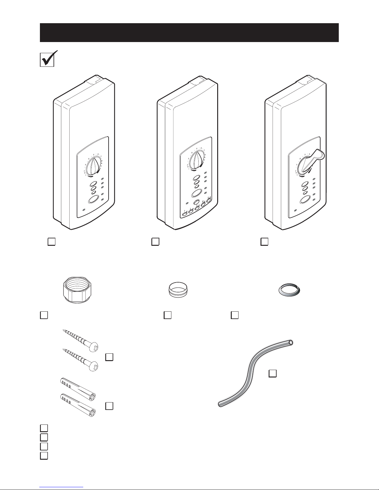
PACK CONTENTS
1 x Installation and User Guide
1 x Installer Checklist
1 x Installation Template
1 x Guarantee Card
1 x Olive 1 x Compression Nut 1 x Tap Connector Adaptor
(for fi tting to existing tap connector)
1 x Mira Advance ATL
Standard or Standard Extra
(Whale Shower Drain Pump
supplied separately)
2 x Wall Screws
2 x Wall Plugs
1 x Earth Sleeve
Or Or
Tick the appropriate boxes to familiarize yourself with the part names and to
confi rm that the parts are included.
1 x Mira Advance ATL
Memory
1 x Mira Advance ATL
Flex or Flex Extra
(Whale Shower Drain Pump
supplied separately)
7
5
6
4
7
3
8
2
9
1
1
2
3
4
5
Flow
High
Medium
Temperature
Stop
Low
Reset Low Pressure
5
6
4
7
3
8
2
9
1
Flow
High
Medium
Temperature
Stop
Low
Reset Low Pressure
5
6
4
7
3
8
2
9
1
1
2
3
4
5
Flow
High
Medium
Temperature
Stop
Store
Low
Reset
Low Pressure
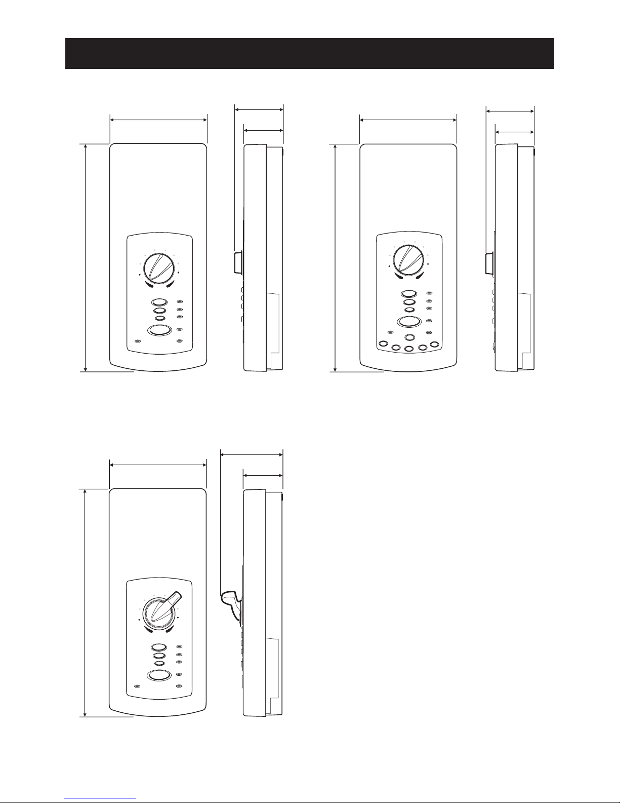
DIMENSIONS
168 mm 168 mm
168 mm
Advance A TL Flex
or Flex Extra
Advance A TL Standard
or Standard Extra
Advance A TL Memory
84.5 mm
68 mm
84.5 mm
68 mm
395 mm395 mm
395 mm
110 mm
68 mm
All dimensions are nominal

8
SUPPLY/SPECIFICATIONS
Plumbing Supply
Supply Source Mains cold water only
Recommended Minimum
Dynamic Pressure*
100 kPa (1.0 bar)
Maximum Static Pressure 1000 kPa (10 bar)
Minimum Static Pressure** 20 kPa (0.2 bar)
Maximum Inlet Temperature 28°C
Minimum Inlet Temperature 2°C
Inlet/Outlet Connections ½" BSP male fitting
Electrical Supply
Nominal Rating at 230 V 8.0 kW 9.0 kW
Nominal Rating at 240 V 8.7 kW 9.8 kW
Supply Fuse/Circuit Breaker
8.7 kW 40 Amps
9.8 kW 45 Amps
Residual Current Device RCD
(Strongly Recommended)
30 mA
Supply Cable
No larger than 16mm²
Note: Refer to current IEE
regulations to determine
minimum cable size.
Isolation Switch
45 Amp Double pole, with
3mm contact separation.
Maximum Ambient T emperature 30°C
Minimum Ambient T emperature 2°C
* Thermostatic performance will be maintained down to 50 kPa (0.5 bar) with reduced flow
performance.
** Static pressure must never fall below 20 kPa (0.2 bar) when other draw offs are in use, e.g. fl ushing
toilet. This is the minimum pressure required to keep the fl ow valve closed.
Standards and Approvals
The Mira Advance ATL complies with the requirements of the BEAB Care Mark
Standard and the relevant directives for CE marking.
Patents and Design Registration
Design Registration: 2 087 315, 2 087 316, D.13322, D.13320
Patents: 2269466, 2270370, 2298478, 2298479, 2298481
9
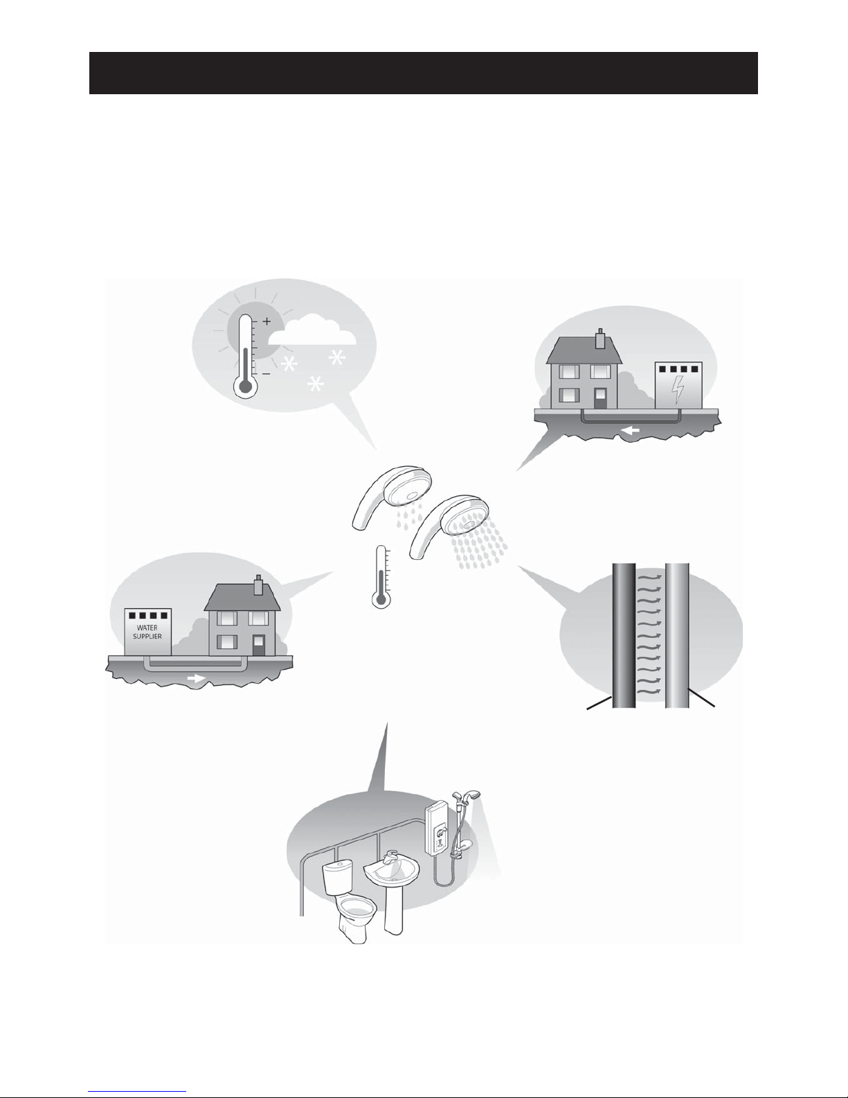
SHOWER PERFORMANCE
Seasonal changes
affecting water supply
temperature.
Changes of incoming
supply pressure.
Changes of incoming
supply voltage.
Mains cold water draw
off, e.g. toilet, wash
basin etc.
Heat transfer due to
position of mains cold
water pipe.
Changes in Flow Rate
(force of shower).
Temperature remains
constant.
What affects shower performance?
The shower unit's top priority is to keep the desired water temperature constant.
To maintain this temperature, the shower may have to automatically change the
rate of water fl owing through the unit. Any of the following conditions can cause the
shower to change the fl ow rate (force of the shower) in order to keep the temperature
constant. Most changes are minor and will go unnoticed.
hot pipe
mains cold
pipe
E.g.
Positioned next to hot
water pipe.
Routed through heated
area such as loft or
airing cupboard.

10
General Notes
This product works best when supply temperatures and pressures remain
stable and within the product specifi cations, refer to section "Specifi cations".
If the supply conditions fall outside the specifi cations, the shower may go into
a safe shut down condition.
1. Plumbing
Refer to section: "Important Safety Information" fi rst.
1.1 Do not use sealing compounds on any pipe fi ttings or joints.
Supply pipework MUST be fl ushed to clear debris before connecting the Mira
Advance ATL. Debris will reduce the performance of the unit.
1.2 Avoid running the pipework through excessively hot or cold areas such as hot
loft spaces, airing cupboards, or in close proximity to hot water pipes. If this
cannot be avoided, we would recommend insulating the pipes.
1.3 Never fi t the unit to hot water supplies or to gravity systems of any description.
Only fi t the product to a mains cold water pipe.
1.4 The Mira Advance A TL is suitable for installation within a shower area and must
be positioned over a water catchment area with the controls at a convenient
height for the user . The shower fi ttings should be positioned so that the handset
discharges down the centre line of the bath, or across the opening of a shower
cubicle, and must be directed away from the Mira Advance ATL.
1.5 The Mira Advance ATL is fi tted with an inlet connector assembly that is designed
to accept water supplies from the top or bottom. The water supply can be fed with
15 mm pipe or 10 mm microbore pipe, suitably adapted for the inlet connector
assembly . If 10 mm microbore is used, then an allowance for increased pressure
loss must be made to make sure that the minimum maintained inlet pressure
of 1 bar is achieved, refer to section: "Specifi cations".
1.6 The Mira Advance A TL must be fi tted onto the fi nished wall surface i.e. on top of
the tiles. Do not block the air ventilation gaps around the sides of the unit, either
by tiling up to the sides of the unit or by using a sealant around the case (Small
pillars moulded on to the back of the case allow air circulation). The appliance
is designed to be ventilated. Failure to do this may cause product failure.
1.7 We recommend that a non-restrictive (free fl owing) isolating valve is fi tted in
the cold water supply pipe to allow maintenance of the Mira Advance ATL. Do
not fi t a valve that has a loose washer plate (jumper) as this can lead to a build
up of static pressures.
1.8 When installed in very hard water areas (above 200 ppm temporary hardness)
your installer may advise the installation of a water treatment device, to reduce
the effects of limescale formation. Malfunction of the Mira Advance ATL due to
excessive limescale formation is not covered by the manufacturer's guarantee.
Your local water company will be able to advise the hardness of water in your
area.
INSTALLATION REQUIREMENTS
11
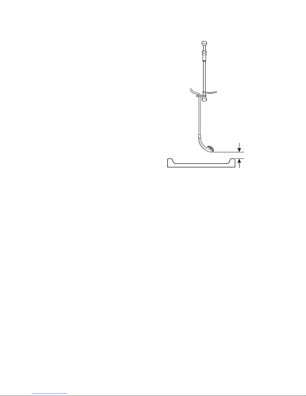
1.9 The hose should be fi tted through the hose retaining ring to prevent the handset
from dropping below the spill-over level of the bath or shower , which could lead
to contamination from backsiphonage.
The hose retaining ring should meet
the majority of user requirements
for shower installations with fl exible
outlet fi ttings. However, there will be
occasions when the hose retaining
ring will not provide a suitable solution.
In these instances an outlet double
checkvalve, e.g. the Mira DCVH, must be fi tted, refer to section:
"Accessories". The inclusion of the
Mira DCV -H will increase the required
supply pressure typically by 10 kPa
(0.1 bar).
Caution! Double checkvalves, fi tted
in the inlet supply to the appliance,
cause a pressure buildup, which could
exceed the maximum static inlet pressure for the appliance.
1.10 Avoid layouts where the shower hose will be sharply kinked. This may reduce
the life of the hose.
Spill-over
Level
25 mm
minimum

12
2. Electrical
Refer to section: "Important Safety Information" fi rst.
2.1 In a domestic installation, the rating of the electricity supplier ’s fuse and the
consumer unit must be adequate for the additional demand. All Mira Advance
ATL electric showers are high power units, therefore it is essential to contact
your electricity supplier to make sure that the supply is adequate for the
product. Voltage drop due to local heavy demand will reduce the shower’s
performance.
2.2 The Mira Advance ATL must be earthed by connecting the supply-cable earth
conductor to the earth terminal.
Supplementary bonding: Within the bathroom or shower room, all accessible
conductive parts of electrical equipment and extraneous conductive parts (metal
parts) that are likely to introduce earth potential, must be electrically bonded to
earth using a minimum cable size of 4.0 mm
2
if the cable is not mechanically
protected, (2.5 mm
2
if mechanically protected).
2.3 The minimum required supply cable size must conform to BS 7671.
2.4 As a guide only, and in accordance with BS 7671 we recommend close circuit
protection:
i.e. 8.7 kW = 40 Amp
9.8 kW = 45 Amp
It is strongly recommended that a 30 mA Residual Current Device (RCD) is
included in the electrical circuit. This may be part of the consumer unit or a
separate unit.
A separate, permanently connected supply is taken from the consumer unit to
the appliance through a double-pole switch, which has at least 3 mm contact
separation. The switch can be a ceiling mounted pullcord type within the shower
room or a wall mounted switch in an adjacent room.
2.5 DO NOT twist the individual cable cores of either the live or neutral conductors,
as this will prevent them from entering the terminal block.
2.6 DO NOT exert strain on the terminal block. Make sure that the electrical
connections are tightly screwed down.
2.7 DO NOT turn on the electrical supply until the plumbing has been completed.
13
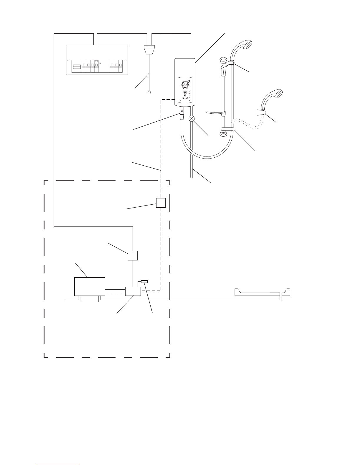
Plumbing and Electrical Schematic Diagram
5
4
7
3
8
2
9
1
L
ow
P
re
s
s
u
r
e
Hig
h
Medium
L
ow
S
to
p
Tem
p
e
r
a
t
u
r
e
S
e
r
v
ic
e
Flow
Mira Advance A TL
Optional Outlet
Double Checkvalve
45 A Double-pole
Isolating Switch
Hose
Retaining
Ring
Mains-fed Cold
Water Supply
Clamp
Bracket
RF2 Handset
Holder
Consumer Unit
Isolating
Valve
Terminal Block
Switched
Spur
Transformer/
Controller
Shower
Drain Pump
Standard Extra & Flex Extra
models only
Signal Cable
Push Button
Override Switch
14
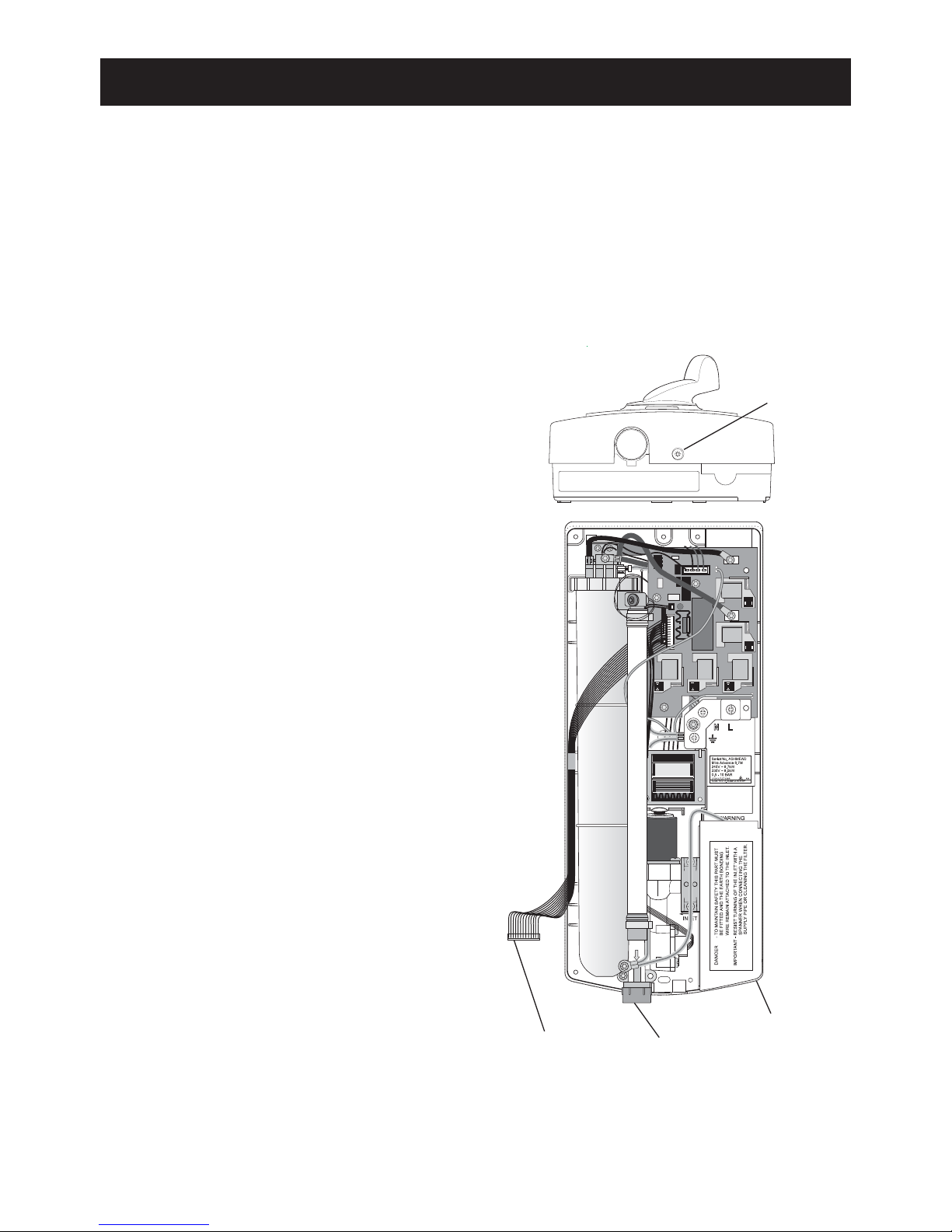
INSTALLATION
Plumbing Connection
1.1 Unscrew the Case Securing Screw
and carefully pull the bottom of the
Cover outwards and upwards off the
Case.
1.2 Remove the Inlet Shield, located over
the Inlet Connector Assembly.
1.3 When deciding the position of the
Mira Advance ATL on the wall, allow
100 mm minimum clearance to
the right hand side of the case, to
provide unrestricted access to the
inlet connector, for installation and
maintenance. Allow 10 mm minimum
clearance from the top of the case to
allow the cover to be removed.
1.4 Determine whether the cold water
and cable supplies will be top (falling),
bottom (rising), or rear inlet to the
Mira Advance A TL. Provision must be
made for routing the signal cable from
the appliance to the Shower Drain
pump (up to 2 m), this applies to the
Standard Extra and Flex Extra models
only.
Note! Rear inlet must allow access to
the water supply pipe fi ttings.
Refer to section: "Important Safety Information" fi rst.
This installation covers all models of the Mira Advance ATL Thermostatic
shower.
Warning! Isolate the electrical and water supplies before proceeding with the
installation of the Mira Advance ATL. The electricity supply must be turned off at the
mains and the appropriate circuit fuse removed, if applicable.
Note! Bottom inlet is illustrated for clarity in these instructions.
Case Securing
Screw
13-Way
Multi-Connector
Inlet Shield
Transit
Sealing Cap
(outlet)
 Loading...