

Mira Platinum Installation Manual
1
These instructions are to be left with the user
Installation Guide
Mira Platinum

2
Contents
Introduction ................................................................................................3
Products Covered by this Guide ................................................................3
Patents and Design Registration ...............................................................3
Important Safety Information .....................................................................4
Pack Contents Checklist ...........................................................................6
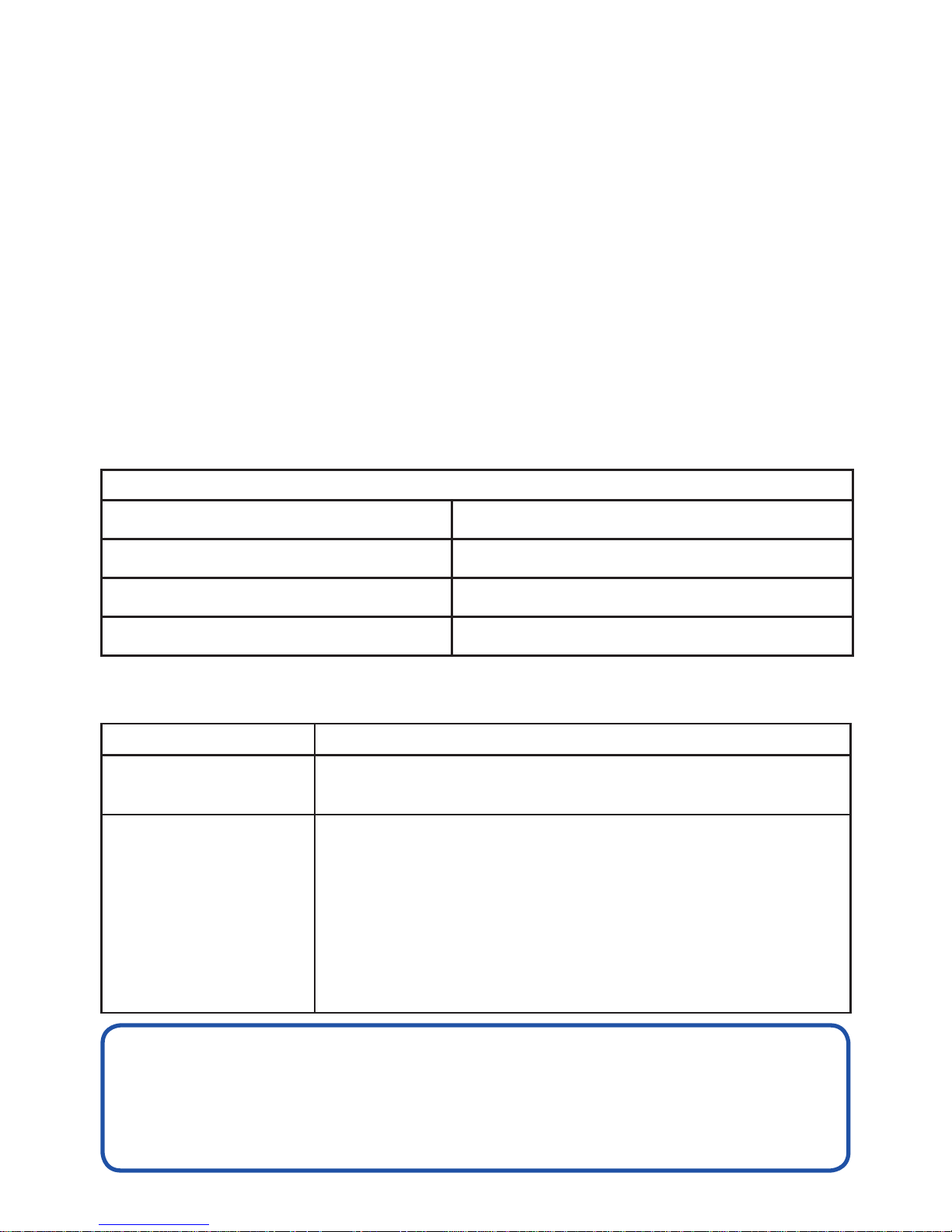
Specications ..........................................................................................10
Installation ...............................................................................................12
Commissioning ........................................................................................29
Fault Diagnosis ........................................................................................31
Maintenance ............................................................................................35
Spare Parts .............................................................................................36
Accessories .............................................................................................39
Dimensions ..............................................................................................40
Disposal and Recycling ...........................................................................41
Customer Services ..................................................................................43
3
Introduction
Thank you for purchasing a quality Mira product. To enjoy the full potential of your
new product, please take time to read this guide thoroughly. Having done so, keep
it handy for future reference.
The Mira Platinum Mixer Valve is designed to be used with the Mira Platinum
showerhead and ttings.
Products Covered by this Guide
Mira Platinum Digital Mixer - High Pressure/Combi Valve
Mira Platinum Digital Mixer - Pumped Valve.
Mira Platinum Wireless Controller.
Mira 360 Fittings (Ceiling Fed or Rear Fed).
Recommended Usage
Domestic
Light Commercial
Heavy Commercial
Healthcare
If you experience any difculty with the installation or operation
of your new shower, then please refer to the Fault Diagnosis section,
before contacting Kohler Mira Ltd.
Our telephone and fax numbers can be found in the back of this guide.
Patents and Design Registration
Design Registration 001065023-0003
Patents GB: 2 392 225, 2 421 297
USA: 7 240 850
Patent Applications
UK:
0723827.2
0715612.8
0804172.5
Euro: 03254070.0
USA: US-2007-0221740-A1
PCT/GB2008/004020
WO 2009/022112

4
Important Safety Information
Warning!
Follow all warnings, cautions and instructions contained in this guide, and
on or inside the appliance.
1. THIS APPLIANCE MUST BE EARTHED. ENSURE SUPPLEMENTARY
BONDING COMPLIES WITH THE “REQUIREMENTS FOR ELECTRICAL
INSTALLATIONS”.
In accordance with the current edition of ’The Plugs and Sockets etc. (Safety)
Regulations’ in force at the time of installation, the Mira Digital Mixer Valve is
intended to be permanently connected to the xed electrical wiring of the mains
system. A means for electrical isolation of the appliance shall be provided in the
xed wiring in accordance with local wiring regulations.
2. Products manufactured by us are safe and risk-free, provided that they are
installed, used and maintained in good working order, in accordance with our
instructions and recommendations.
3. Isolate the electrical and water supplies before connecting to the appliance.
4. Mains connections are exposed when the cover of the Digital Mixer Valve is
removed.
5. Make sure that any pipework that could become frozen is properly insulated.
6. Having completed the installation, make sure that the user is familiar with the
operation of the appliance.
7. Make sure that this guide is left with the user.
8. DO NOT commission this appliance if water leaks from the unit.
9. Only Mira recommended outlet ttings should be used.
10. Ensure all electrical connections are tight, to prevent overheating.
11. This product is not suitable for areas with high humidity (i.e steam rooms).
Please consult your installer.
Installation must be carried out in accordance with these instructions and by
designated, qualied and competent personnel.

5
Caution!
1. Read all of these instructions and retain this guide for later use.
2. The electrical installation must comply to “BS 7671 - Requirements for Electrical
Installations”, commonly referred to as the IEE Wiring Regulations - Part 7, or
any particular regulations and practices, specied by the local electricity supply
company.
3. The plumbing installation must comply with the requirements of UK Water
Regulations/Bye-laws (Scotland), Building Regulations or any particular
regulations and practices, specified by the local water company or water
undertakers.
4. Make sure that you fully understand how to operate this shower and make sure
that it is properly maintained in accordance with the instructions given in this
manual.
5. The appliance is not intended for use by persons (including children) with reduced
physical, sensory or mental capabilities, unless they are supervised or have been
given instruction concerning the use of the appliance by a person responsible
for their safety.
6. Sunburn or skin conditions can increase your sensitivity to hot water. Make sure
that you set the shower to a cooler temperature.
7. If any of the following conditions occur, isolate the electricity and water supplies
and refer to section ”To contact us”, in the back pages of this guide.
• If the cover is not correctly tted and water has entered the
appliance case.
• If the case is damaged.
• If the appliance begins to make an odd noise, smell or smoke.
• If the appliance shows signs of a distinct change in performance,
indicating a need for maintenance.
• DO NOT operate if water leaks from the appliance.
• DO NOT operate this appliance if it is frozen. If suspected of being
frozen, isolate and contact us for advice.
6
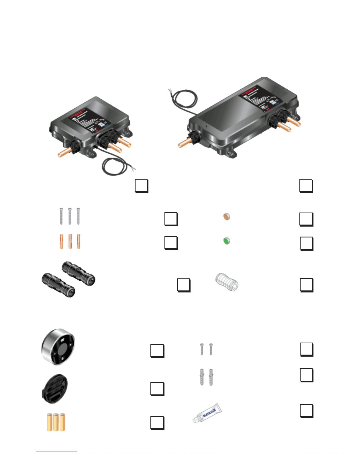
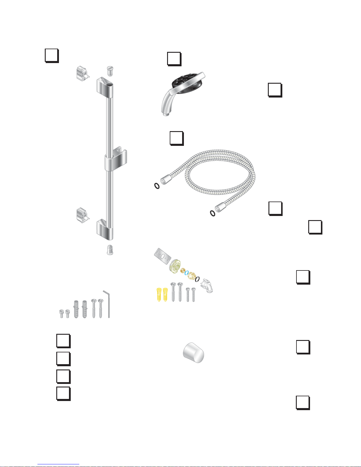
Pack Contents Checklist
Digital Mixer Valve
Wireless Controller
Tick the appropriate boxes to familiarise yourself with the part names and to
conrm that the parts are included.
1 x Orange
Flow Regulator
3 x Fixing Screws
2 x Fixing Screws
2 x Wall Plugs
1 x Silicon Glue
Digital Mixer High Pressure/Combi Valve
Digital Mixer - Pumped Valve
2 x Push-Fit Isolators
3 x Wall Plugs
1 x Green
Flow Regulator
1 x Outlet
Connector
1 x Wireless
Controller
1 x Backplate
3 x AA Batteries
OR
7
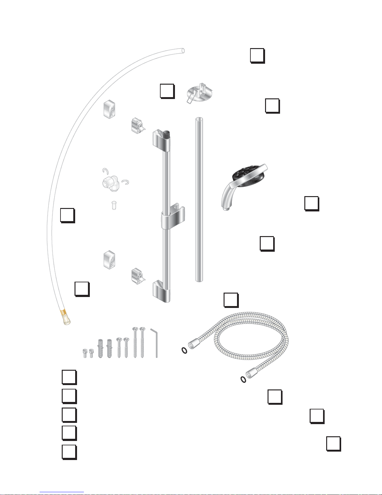
Ceiling Fed Fittings
1 x Installation Template
(not shown)
1 x Ceiling Plate
1 x Showerhead
1 x Extension
1 x Slide Bar
Assembly
2 x Brackets
2 x Hex Screws
2 x Wall Plugs
2 x 45mm Screws
2 x 70mm Screws
1 x Hex Key
1 x Elbow Kit
2 x Spacers
2 x Rubber Washers
1 x Hose
1 x Plastic Pipe
8
2 x Hex Screws
2 x Wall Plugs
2 x 45mm Screws
1 x Hex Key
1 x Installation Template
(not shown)
2 x Rubber Washers
1 x Right Angle
Connector (RAC) Kit
1 x Right Angle
Connector Shroud
1 x Hose
2 x Brackets
1 x Slide Bar
Assembly
2 x End Plugs
1 x Showerhead
Rear Fed Fittings

9
Documentation
1 x Wireless Controller User Guide
1 x Showerhead User Guide
1 x Customer Support Brochure
10
Specications
Standards and Approvals
The Mira Platinum complies with all relevant directives for CE marking.
The Mira Platinum is a type 1 electronic, independently mounted control for
surface mounting.
General
Pollution Degree 2
Rated Impulse Voltage 2.5 kV
Suitable for Drinking Not Suitable
Connections 15 mm Compression/Pusht
Mira Digital Mixer Valve High Pressure
Pressures
Maximum Static Pressure 1000 kPa (10 bar) = 100 m max. total head
Maximum Maintained Pressure 500 kPa (5 bar) = 50 m max. total head
Minimum Maintained Pressure 50 kPa (0.5 bar) = 5 m max. total head
Supply Pressure Differential Nominally Equal
Temperatures
Maximum Temperature (factory preset) 45 °C
Maximum Temperature (setting range) 39 °C - 48 °C
Minimum Temperature Thermostatic control down to 30 °C
Hot Water Range 55 °C - 65 °C
Cold Water Range 1 °C - 20 °C
Temperature Stability ± 1 °C at recommended supply conditions
Ambient Temperature 1 °C - 40 °C
Maximum Relative Humidity 95% non-condensing
Flow Rates and Times
Nominal Flow Rates (will vary depending
on inlet maintained pressure and spray
mode)
Max @ 1.0 bar = 16l/min
Min @ 1.0 bar = 5l/min
Electrical
Supply Voltage 230V RMS 50 Hz ± 10%
Maximum Load 20 W
11
Mira Digital Mixer Valve Pumped
Pressures
Maximum Static Pressure 100 kPa (1 bar) = 10 m max. total head
Maximum Maintained Pressure 100 kPa (1 bar) = 10 m max. total head
Minimum Maintained Pressure 1 kPa (0.01 bar) = 0.1 m min. total head
Supply Pressure Differential Nominally Equal
Temperatures
Maximum Temperature (factory preset) 45 °C
Maximum Temperature (settable range) 39 °C - 48 °C
Minimum Temperature Thermostatic control down to 30 °C
Full Cold also selectable
Hot Water Range 50°C - 65°C
Cold Water Range 1°C - 20°C
Temperature Stability ± 1°C at recommended supply conditions
Ambient Temperature 1°C - 40°C
Maximum Relative Humidity 95% non-condensing at 30 °C
Flow Rates and Times
Flow Rates (will vary depending on inlet
maintained pressure and spray mode)
Max @ 0.01 bar = 16 l/min
Min @ 0.01 bar = 6 l/min
Electrical
Supply Voltage 230V ± 10%, RMS 50 Hz
Maximum Load 200 W at 230V AC
12
Installation
General
The installation must be carried out in accordance with these instructions, and
must be conducted by designated, qualied and competent personnel.
The installation must comply with any particular regulations and practices,
specied by the local water supply regulations.
The Digital Mixer Valve may be installed in a loft space, under the bath
or in a convenient cupboard space provided there is enough room for
maintenance (e.g. Removal of Digital Mixer Valve Lid). Failure to do so may
result in an inability to carry out any maintenance. Safe and easy access to
the product should be available at all times.
Isolating valves must be installed to both inlets (supplied) and outlet, close to the
Digital Mixer Valve for ease of maintenance.
Caution! Risk of product damage. The Digital Mixer Valve must be installed
in a dry, ventilated area where it will not freeze.
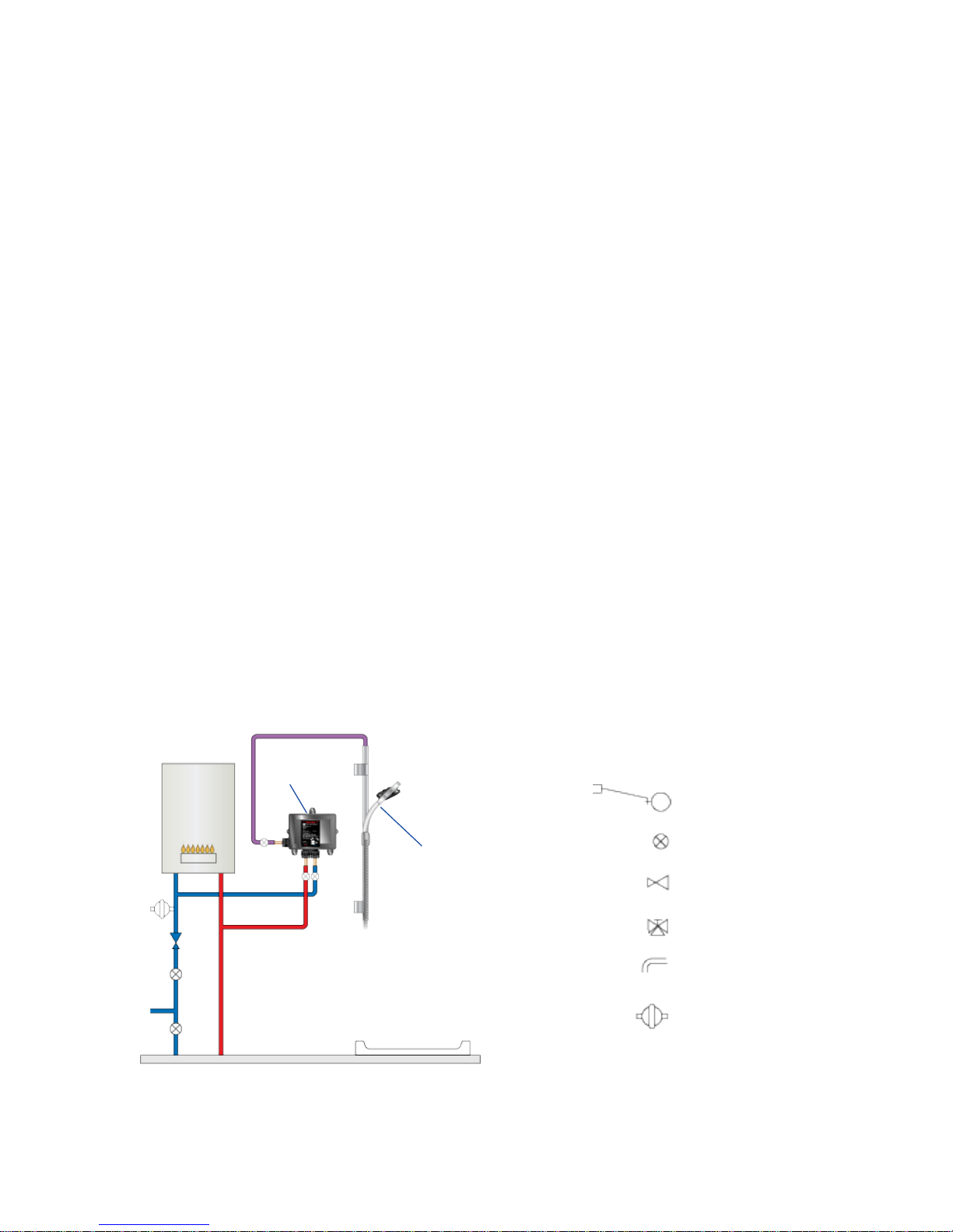
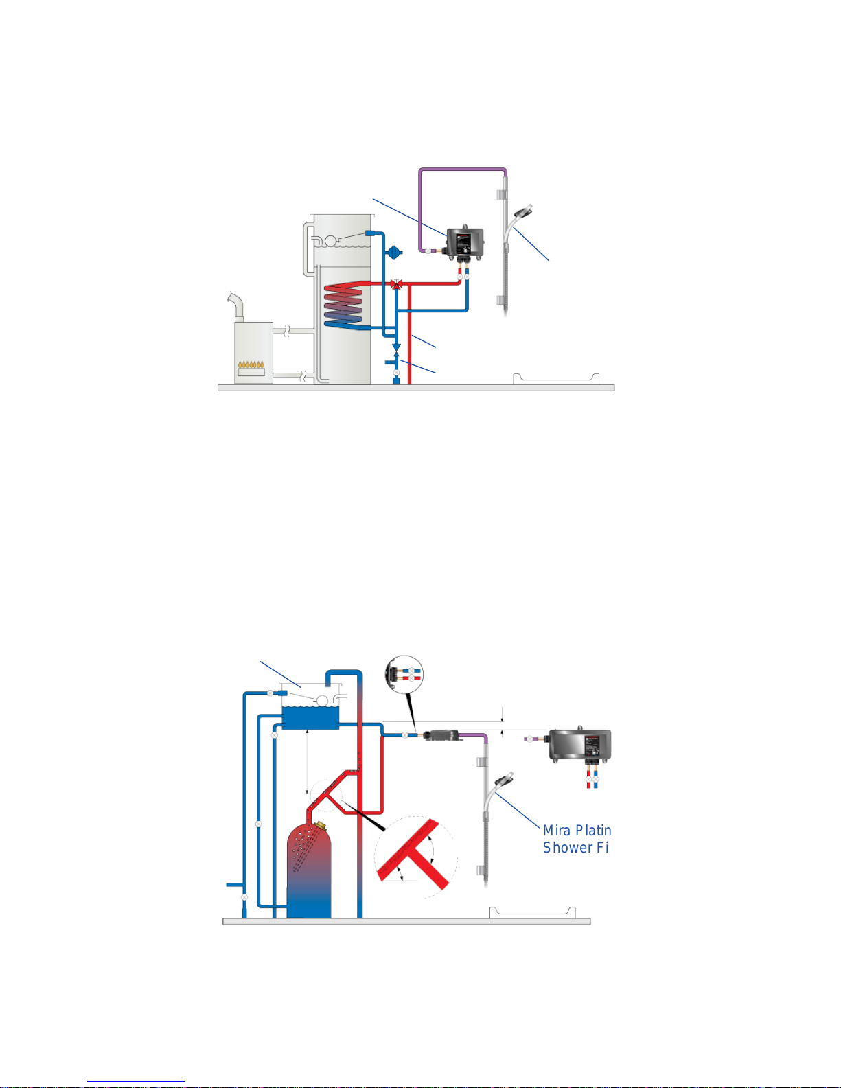
1. Instantaneous Multipoint Water Heaters and Combination Boilers
Only install the High Pressure Digital Mixer Valve with a multipoint gas water
heater or combination boiler of a fully modulating design (i.e. where the water
draw-off rate indirectly controls the gas ow rate to the burner).
Typical Suitable Installations:
Mira Platinum
Shower Fittings
Digital Mixer
Valve
Float Valve
Key to Symbols
Isolating Valve
Tempering Valve
Overow Indicator
Mini Expansion
Vessel
Pressure Reducing
Valve
COLD HOT
Caution! Risk of product damage. Do not t the Mira Digital Mixer - PUMPED
VALVE with Instantaneous Multipoint Water Heaters or Combination Boilers.
13
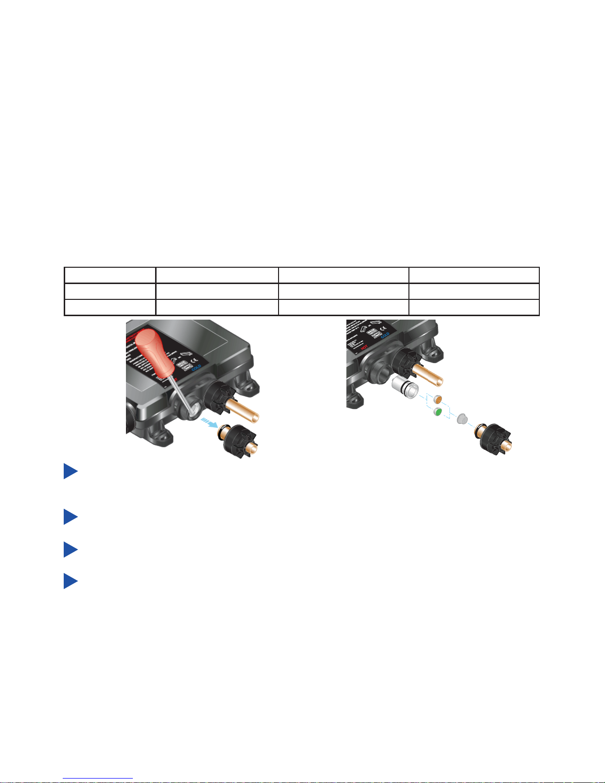
Use of Flow Regulators with Combination Boilers
The Mira Digital Mixer Valve can demand hot water quicker than some
instantaneous water heaters/combination boilers can provide, especially in winter
when the mains water is colder. A ow regulator may need to be used to ensure
that the Digital Mixer Valve can deliver a full range of water temperatures. The
table indicates the ow regulator to be tted in the hot water inlet of the Mira
Digital Mixer Valve.
Boiler Rating 24 kW (80,000 Btu/h) 30 kW (100,000 Btu/h) 36 kW (120,000 Btu/h)
Flow Regulator 7 litres/min 9 litres/min Not required
Colour White Green White/Orange -
Use of Warm-up Feature with Combination Boilers
When using the warm-up feature (see User Guide) with the Digital Mixer Valve
supplied via an instantaneous water heater/combination boiler, the user may
experience a brief temperature uctuation. This is caused by the usual operation
of a standard instantaneous water heater/combination boiler whereby the boiler
will turn off when the ow is stopped (as happens after the warm-up sequence
has been completed). Upon restart of the shower, a cold shot will be ushed
through followed by a brief hot shot until the hot water supply has stabilised.
An expansion vessel must be tted (and regularly maintained) if any form of
backow prevention device is tted, e.g. non-return valve or PRV. This will ensure
that excess expansion or pulse pressures do not damage the product or plumbing
system. The expansion vessel may already be tted within the boiler (check
with the manufacturer) and is in addition to the normally larger central heating
expansion vessel.
Unscrew hot inlet plastic nuts and remove pipe and seal to gain access to the
checkvalve cartridge and lter.
Use at blade screwdriver to carefully lever cartridge out.
Fit ow regulator in checkvalve cartridge behind lter as shown.
Ret seal, pipe and plastic nut. Plastic nuts require hand tightening only.
14
Mira Platinum
Shower Fittings
3. Gravity Fed Showers
The shower control must be fed from a cold water storage cistern and a hot
water cylinder providing nominally equal pressures. Pipework layouts and
connections must be such that other draw-offs will not effect water supplies to the
shower. It is therefore best practice to have independent hot and cold supplies to
the Low Pressure (pumped) Digital Mixer Valve.
1.0 metre
minimum
100 mm from the lowest level of
water in the tank
Cistern
Minimum 230 litres
Packages of this type, tted with a tempering valve can be used. A drop type
pressure reducing valve must be tted (and regularly maintained) if any form
of backow prevention device is tted, e.g. non-return valve, PRV. This will
ensure that excess expansion or pulse pressures do not damage the product or
the plumbing system. The expansion vessel may already be tted externally or
internally within the thermal store (check with thermal store manufacturer).
90°
30° - 60°
2. Mains Pressurised Instantaneous Hot Water Shower, Heated
from a Thermal Store
Digital Mixer
Valve
COLD
HOT
Mira Platinum
Shower Fittings
Caution! Risk of product damage. Do not t the Mira Digital Mixer - PUMPED
VALVE with Mains Pressurised Systems.
Caution! Risk of product damage. Do not t the Mira Digital Mixer - HIGH
PRESSURE/COMBI VALVE with Gravity Fed Systems.
Air Separation
15
Digital Mixer
Valve
Outlet
Isolators
Isolator
Hot Inlet
Cold Inlet
To Mains
Power Supply
3 amp switched
fused spur
Metal pipework must
be earth bonded
Mira Platinum Shower
Fittings & Wireless Controller
Installation Schematic
A separate, permanently connected supply must be taken from the consumer
unit to the appliance through a 3 amp switched fuse spur.
Inlet and outlet isolating valves must be installed close to the Digital Mixer
Valve for ease of maintenance (recommended maximum 300 mm from the
product on the inlets).
The use of supply-line or zone strainers will reduce the need to remove
debris at the Digital Mixer Valve. The recommended maximum mesh aperture
dimension for such strainers is 0.5 mm.
Pipework must be rigidly supported to avoid any strain on the connections.
A 30 mA Residual Current Device (RCD) must be included in the electrical
circuit. This may be part of the consumer unit or a separate unit.
16
Pipework dead-legs should be kept to a minimum.
Supply pipework layout should be arranged to minimize the effect of other
outlet usage upon the dynamic pressures at the Digital Mixer Valve inlets.
To eliminate pipe debris it is essential that supply pipes are thoroughly
ushed through before connection to the Digital Mixer Valve.
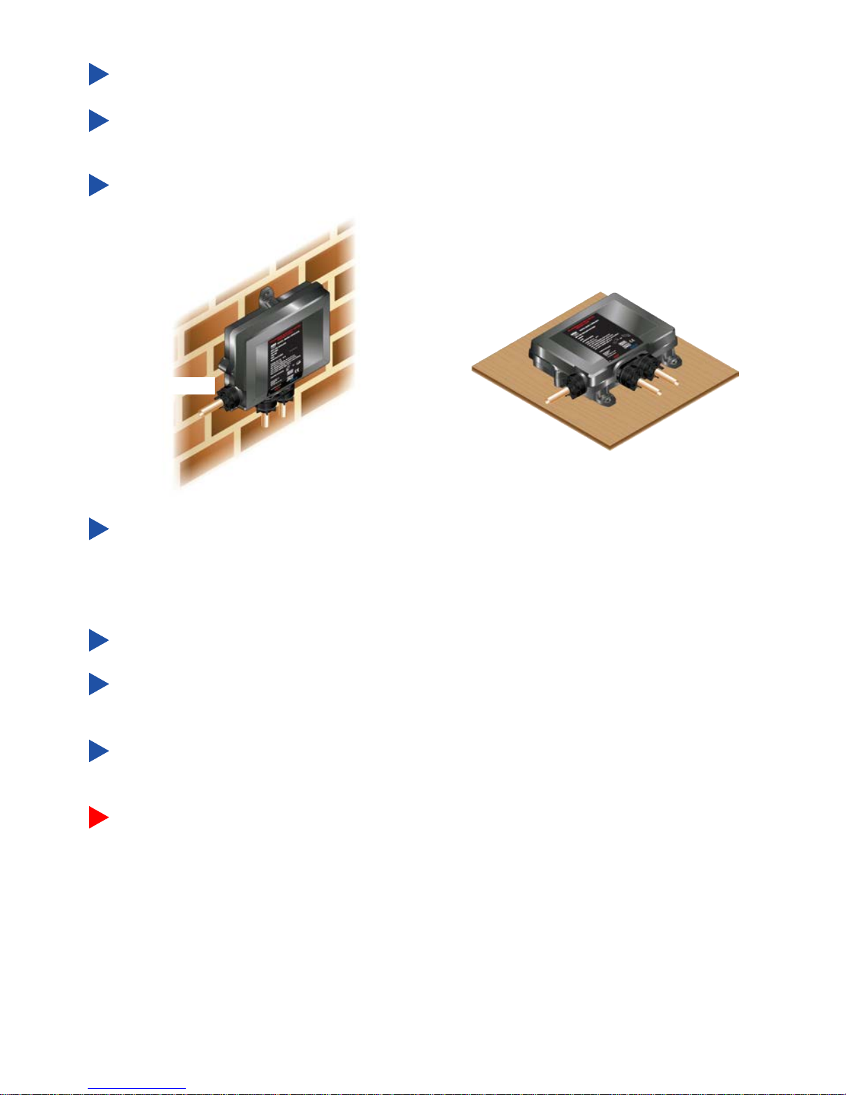
Mounting on a Vertical Surface
Inlets
Outlet
Inlets
Outlet
Mounting on a Horizontal Surface
The Digital Mixer Valve (which contains the thermostatic mixing valve) may
only be orientated in the positions shown when mounted on a vertical or
horizontal surface. Failure to do so will compromise the ability of the unit to
fail-safe and deliver constant blend.
Maximum hot water range 50°C - 65°C.
This appliance is intended for permanent connection to the xed electrical
wiring circuit.
If the supply cords are damaged, they must be replaced by the manufacturer
or a service engineer.
Warning! Turn off the electrical and water supplies before proceeding with
the installation of the appliance. The electricity must be turned off at the
mains and the appropriate circuit fuse electrically isolated, if applicable.
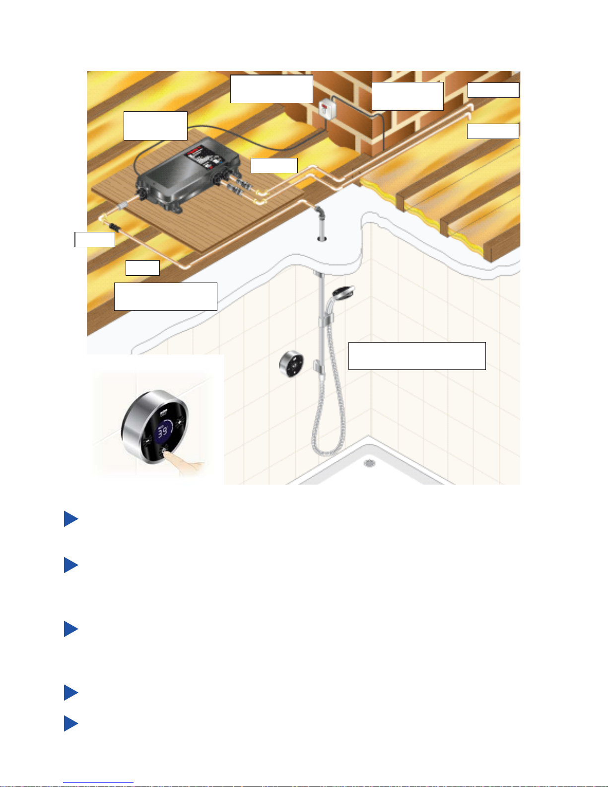
17
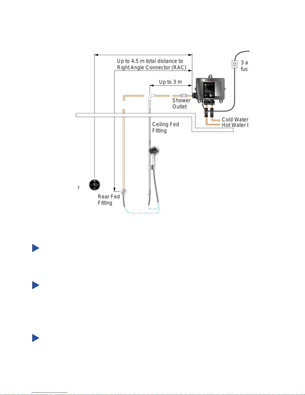
Up to 10 m
3 amp switched
fused spur
Up to 3 m
Ceiling Fed
Fitting
Rear Fed
Fitting
Cold Water Inlet
Hot Water Inlet
Shower
Outlet
Wireless
Controller
Up to 4.5 m total distance to
Right Angle Connector (RAC)
Digital Mixer Valve
Position and Signal Test
The Wireless Controller can be sited up to 10 m from the Digital Mixer Valve.
However, wall thicknesses and construction types may affect the remote signal
strength and thereby reduce the range. The Controller range should be tested
on site prior to installation to ensure shower’s reliability.
Important! When choosing a position for the Digital Mixer Valve in relation to the
Wireless Controller and the Shower Fittings, consider the following points:
The length of pipework running from the Digital Mixer Valve to the Shower Fitting
will have an effect on the showering temperature and the response time when
changing the temperature using the Wireless Controller. The shorter the length
of pipework from the Digital Mixer Valve the better the shower will respond. It
is recommended that this length does not exceed 3 m (Ceiling Fed Fitting) or
4.5 m (Rear Fed Fitting).
The ambient temperature of Digital Mixer Valve site (loft space, airing cupboard
etc...) can have an effect on showering temperature. Insulate all pipework as
required, particularly from the Digital Mixer Valve to the Shower Fitting.
Important! Insulate pipework only. Do not attempt to insulate or cover the
Digital Mixer Valve.
18
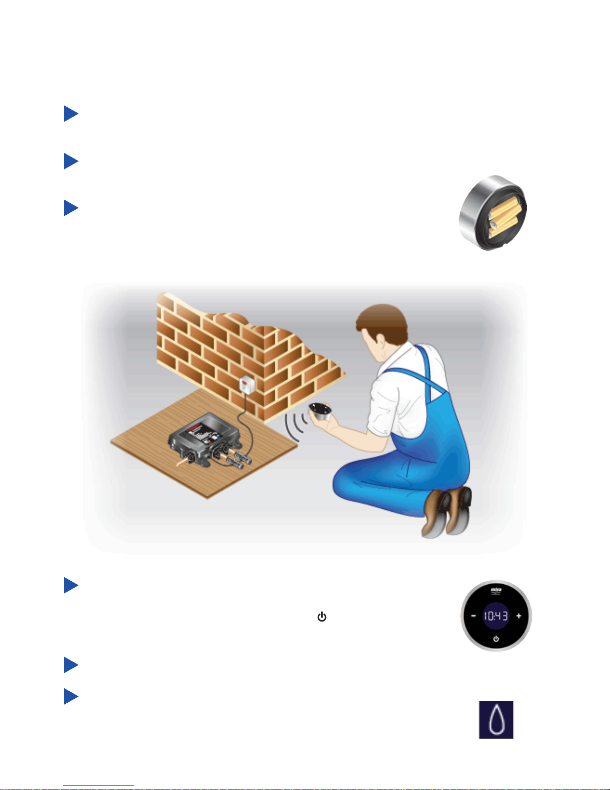
Place the Digital Mixer Valve in the required location, no more than 10 m from
the nal position of the Wireless Controller.
Connect the Digital Mixer Valve to the electrical supply via a 3 amp fused
spur switch.
Bring Wireless Controller to within approximately 1 m of the
Digital Mixer Valve. Fit 3 x AA batteries supplied.
The following procedure details how to assign the Wireless Controller to the Digital
Mixer Valve and test the remote signal strength.
Note! No plumbing connections are required for this test.
The Wireless Controller enters “Clock Setting” function
automatically when batteries are connected. Press “-” to alter
hours and “+” to alter minutes. Press “ ” to set time and exit
“Clock Setting” function.
Switch on electrical supply to Digital Mixer Valve.
Droplet symbol is displayed for approximately 30 seconds.
Do not remove the batteries or switch off the Digital Mixer
Valve. Droplet symbol goes out indicating Digital Mixer Valve
and Wireless Controller have been assigned to each other.
19
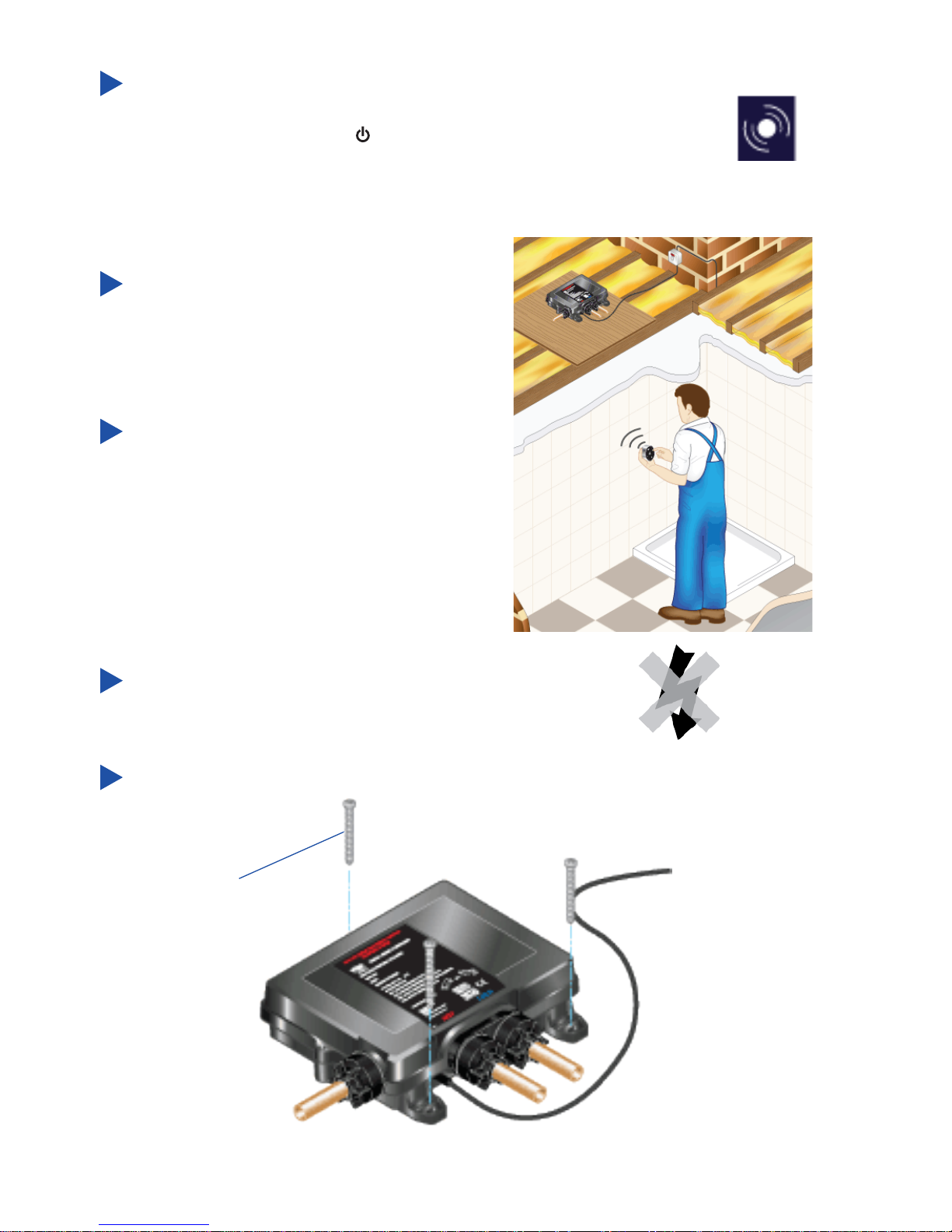
Place Wireless Controller in approximate nal position (no
more than 10 m from Digital Mixer Valve) and test wireless
signal by pressing the “ ” and adjusting the temperature. If
temperature display remains unchanged and “out of range”
symbol is displayed, units are unable to communicate with each
other.
If test fails, reposition unit(s) and
repeat test until satised shower will
work reliably.
Caution! Risk of product damage.
Do not run Pumped Valve (low
pressure version) without a water
supply for longer than 15 minutes
during test.
Isolate electrical supply to Digital
Mixer Valve.
Fixing Screw x 3
Mark the xing holes in the required positions.
20
Drill and plug the xing holes.
Note! Installers may wish to use alternative cavity xings, when installing
onto a dry lined, stud partition, shower cubicle or laminated panel wall
structures. However, these methods of xing are beyond the scope of this
guide.
Secure the Digital Mixer Valve in position with the xing screws (supplied).
Caution! Risk of product damage. Make sure both hot and cold supply
pipes are ushed thoroughly prior to connection to the Digital Mixer
Valve. Any product malfunction caused by pipework debris is not
covered under the guarantee.
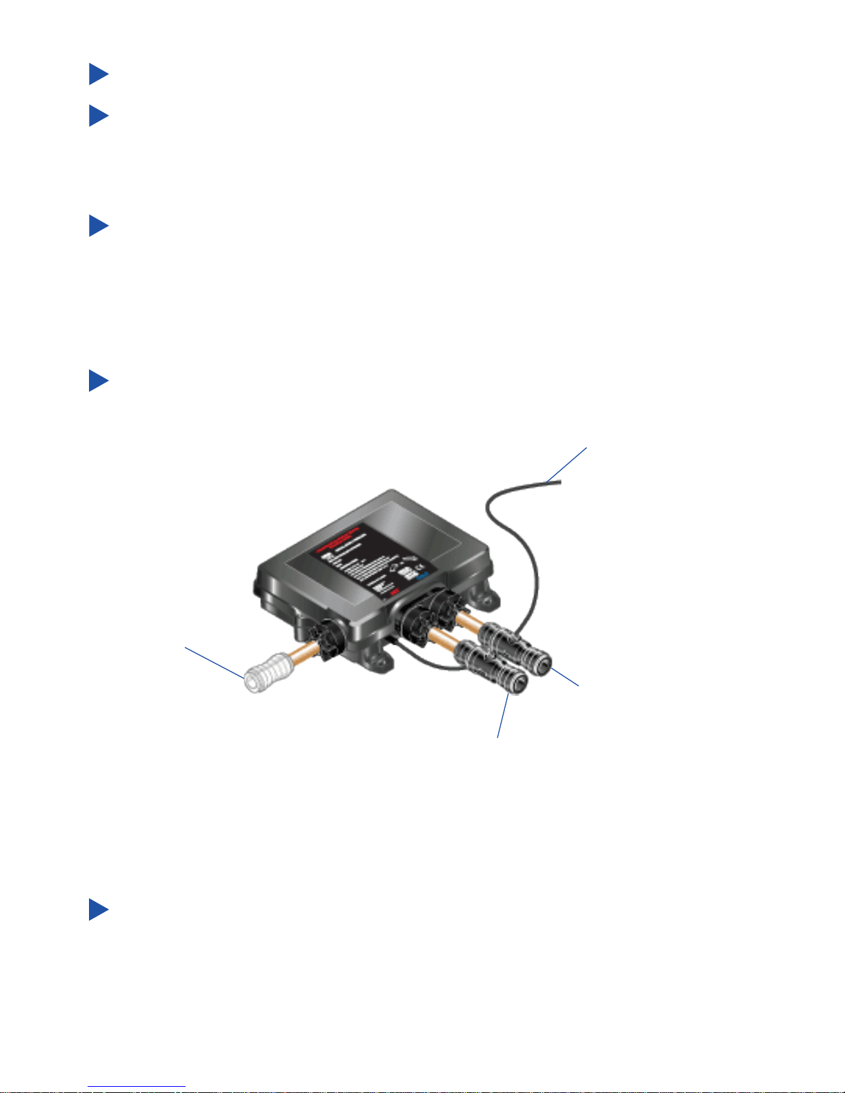
Connect the hot and cold water supply pipes to the Digital Mixer Valve.
Install the Shower Fittings and Wireless Controller (see further instructions).
Wiring to
Fused Spur Box
Push-t connector to the
Shower Fittings
Outlet
Cold Inlet
Hot Inlet
Push-t Isolators tted
to both Inlets
21
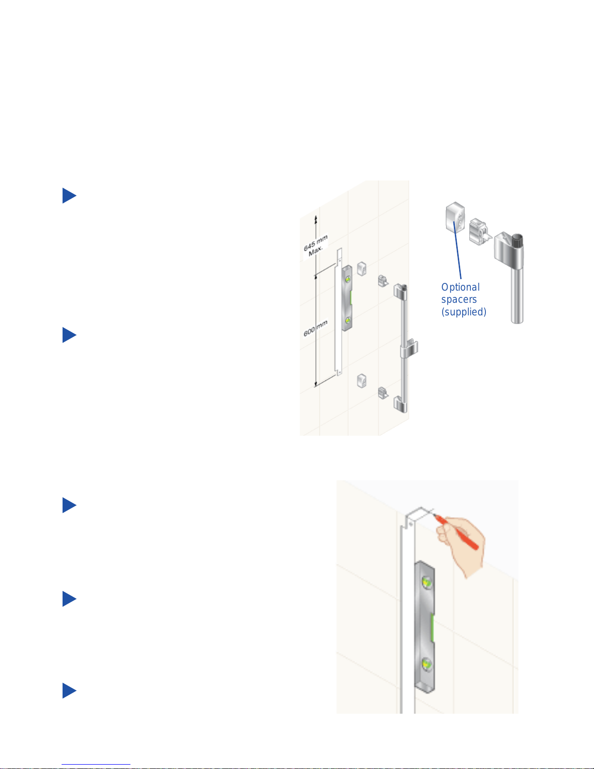
Decide on suitable position for
Slide Bar avoiding buried cables
and pipes in both wall and ceiling.
Make sure slide bar extension will t
through ceiling. Ceiling hole centre
can be altered to avoid roof joists by
using supplied spacers
Using template as guide, mark
positions of the xing holes for Wall
Brackets (600 mm). Upper hole
to be no more than 645 mm from
ceiling.
Note! Use spirit level to make sure
xing holes are vertical.
Fold long end of template and move
up to ceiling. Using upper marked
xing hole as guide, mark centre for
hole in ceiling.
Important! If supplied Slide Bar
spacers are required, centre
distance for hole will increase to
75 mm from wall.
Cut hole in ceiling 45 mm diameter.
Suitable for solid, dry-lined, stud partition, shower cubicle or laminated panel
walls.
The Slide Bar should be xed to the wall at a convenient height for all the family.
It should be positioned so that water sprays down the centre of the bath, or away
from the opening of a shower cubicle. Water should spray away from the Wireless
Controller when the Showerhead is held on the Slide Bar.
Optional
spacers
(supplied)
Shower Fittings - Ceiling Fed
22
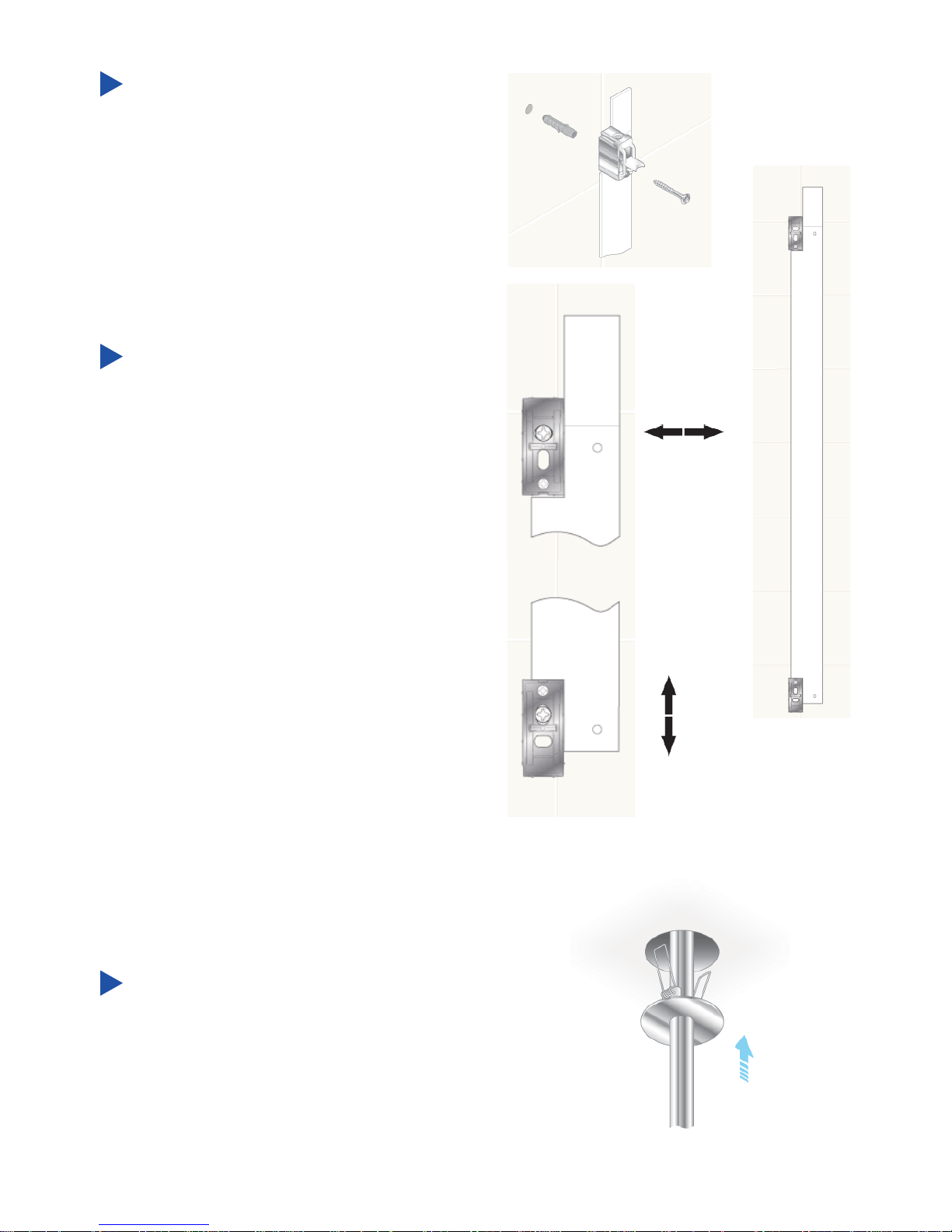
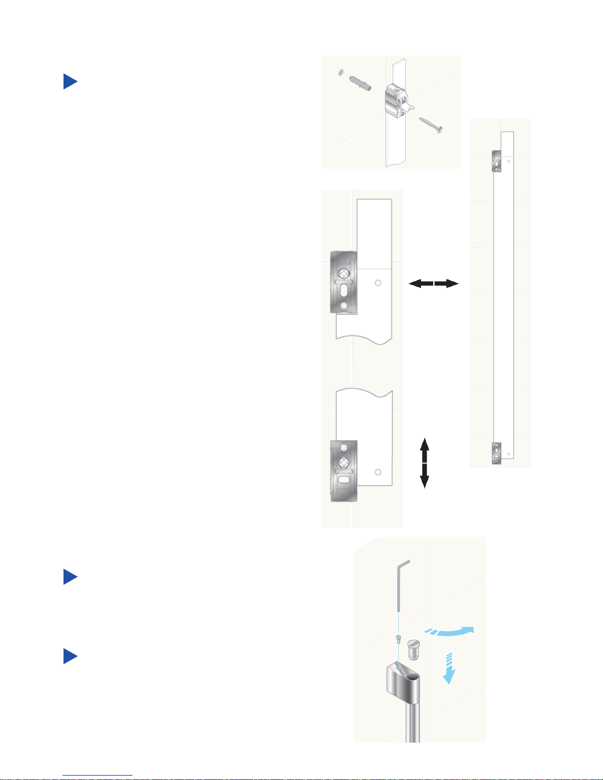
Drill and plug Slide Bar Assembly
xing holes.
Insert xing screws through holes
in Wall Brackets and x to wall. Do
not fully tighten. Use template to
set correct distances between Wall
Brackets. Fully tighten screws. Use
longer xing screws if using spacers
supplied.
Note! Slots in Wall Brackets allow
for adjustment. Use one horizontal
slot and one vertical slot.
Make sure that holes for Slide Bar
Securing Screws are positioned
correctly, as shown.
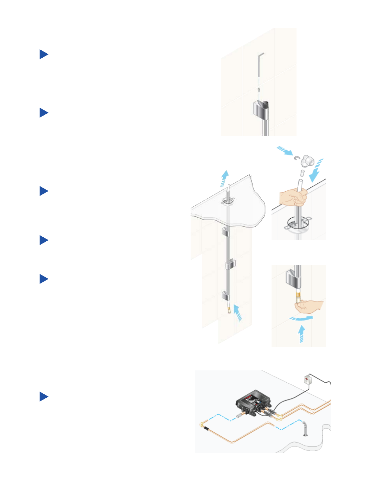
Fit ceiling plate and extension tube.
Note! Extension tube may need to
be shortened. Make sure rough end
is concealed in ceiling.
23
Fit Slide Bar Assembly over Wall
Brackets and secure with screws
supplied. (Do not overtighten.)
Connect ceiling extension tube.
Feed plastic pipe up through the
slide bar and extension into ceiling.
Do not allow any debris to block the
plastic pipe.
Push and twist plastic pipe end until
it “clicks” and locks in place.
Connect plastic pipe in ceiling to
outlet pipe from valve using elbow
supplied. Push all parts together
fully and lock elbow onto pipes
using clips supplied.
Connect elbow to Digital Mixer
Valve. Fit an isolating valve between
to enable easy maintenance. (Pipe
and isolating valve not supplied).
Lock pipe to elbow using clip
supplied.
24
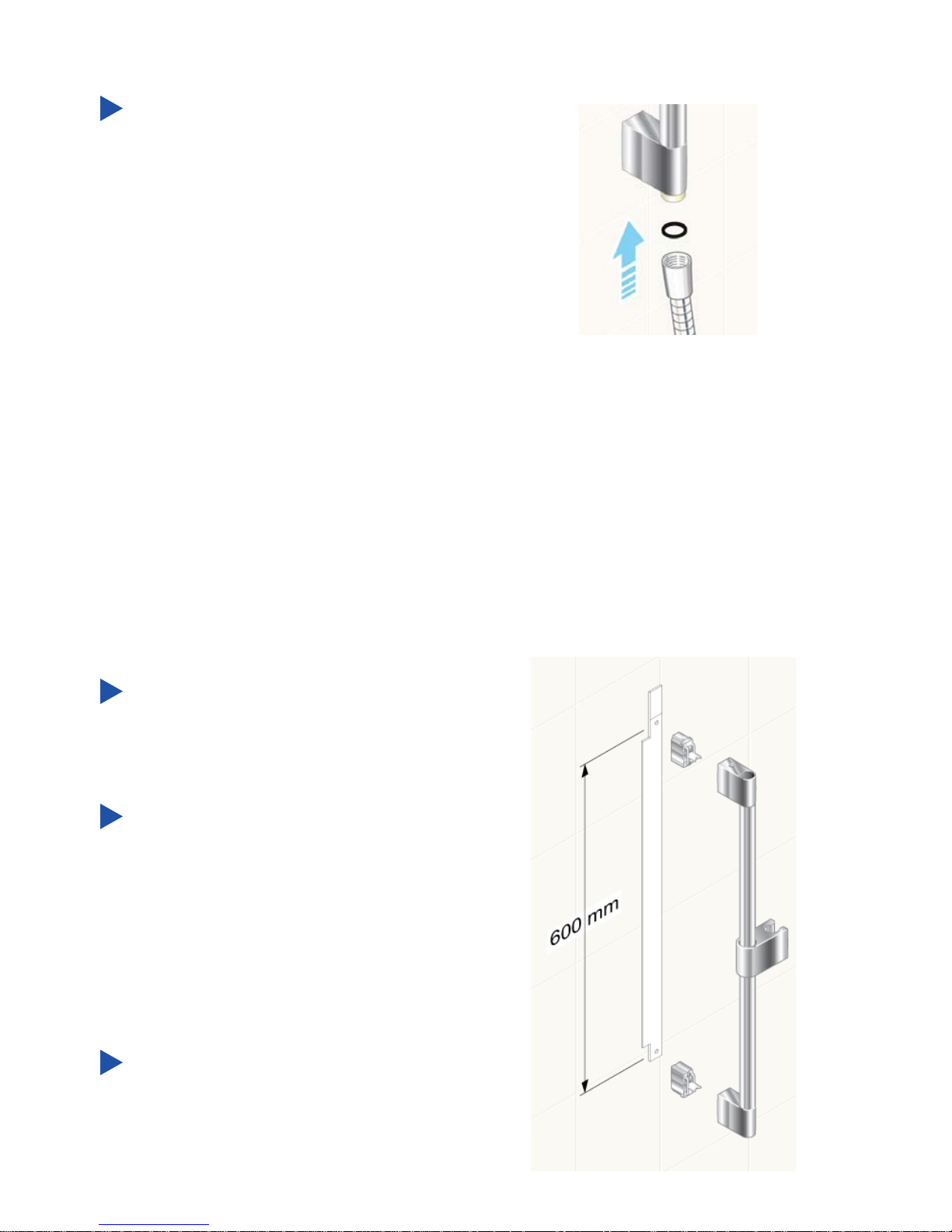
Place rst washer in end of hose,
then attach to pipe end. Do not t
showerhead until after pipework
has been fully ushed through. See
section “Commissioing”.
Shower Fittings - Rear Fed
Decide on suitable position for Slide
Bar avoiding buried cables and
pipes in wall.
Using template as guide, mark
positions of the xing holes for Wall
Brackets (600 mm).
Note! Use spirit level to make sure
xing holes are vertical.
Drill and plug xing holes.
Suitable for solid, dry-lined, stud partition, shower cubicle or laminated panel
walls.
The Slide Bar should be xed to the wall at a convenient height for all the family.
It should be positioned so that water sprays down the centre of the bath, or away
from the opening of a shower cubicle. Water should spray away from the Wireless
Controller when the Showerhead is held on the Slide Bar.
25
Insert xing screws through holes
in Wall Brackets and x to wall. Do
not fully tighten at this stage. Use
template to set correct distances
between Wall Brackets. Fully tighten
screws.
Note! Slots in Wall Brackets allow
for adjustment. Use one horizontal
slot and one vertical slot.
Make sure that holes for Slide Bar
Securing Screws are positioned
correctly, as shown.
Position Slide Bar over Wall
Brackets and secure with screws.
(Do not overtighten.)
Fit Slide Bar End Caps into top and
bottom of Slide Bar Assembly. Push
and twist caps until they “click” and
lock in place.
 Loading...