

Mira Moto, Pace, Miniduo, Minilite, Minilite Eco User Manual
...
MIRA MOTO, MIRA PACE†,
MIRA MINILITE†, AND MIRA MINIDUO†
(†including Eco models)
THERMOSTATIC MIXERS
INSTALLATION & USER GUIDE
These instructions must be left with the user.
1

CONTENTS
Introduction 2
Guarantee 3
Recommended Usage 3
Patents and Design Registration 3
Safety Warnings 3
Pack Contents 4
Exposed Thermostatic Mixers 4
Built-in Thermostatic Mixers 5
Valve Combinations 6
Specications 7
Installation 9
Suitable Plumbing Systems 9
General 9
Exposed Thermostatic Mixers 10
Adjustable Elbow Installation 13
Flow Regulators 19
Operation 23
Commissioning 23
Maximum Temperature Setting 23
Type 2 Valves 24
Fault Diagnosis 26
User Maintenance 26
Filter Replacement 26
Lubricants 27
Cleaning 27
Spare Parts 29
Accessories 31
Customer Service 32
INTRODUCTION
Thank you for purchasing a quality Mira product. To
enjoy the full potential of your new product, please
take time to read this guide thoroughly, having
done so, keep it handy for future reference.
The Mira Moto, Mira Minilite and Mira Minilite Eco
are thermostatic mixers with a single control lever
for on/off and temperature control.
The Mira Pace, Mira Pace with Eco Showerhead,
Mira Miniduo and Mira Miniduo with Eco
Showerhead are thermostatic mixers with
separate on/off and temperature controls.
The thermostatic mixers incorporate a wax
capsule temperature sensing unit, which provides
an almost immediate response to changes in
pressures or temperature of the incoming water
supplies to maintain the selected temperature. An
adjustable maximum temperature stop is provided
which limits the temperature to a safe level.
Inlet lters are tted to protect the thermostatic
cartridge.
These products have been certied as Type 2
valves under the BUILDCERT TMV2 scheme.
They also comply with the Water Supply (water
ttings) Regulations 1999.
If you experience any difficulty with the
installation or operation of your new
thermostatic mixer, please refer to ‘Fault
Diagnosis’, before contacting Kohler Mira Ltd.
Our contact details can be found on the back
cover of this guide.
2

Guarantee
For domestic installations, Mira Showers
guarantee the products listed in this guide against
any defect in materials or workmanship for a
period of three years from the date of purchase
(shower ttings for one year).
For non-domestic installations, Mira Showers
guarantee the products listed in this guide against
any defect in materials or workmanship for a
period of one year from the date of purchase.
For terms and conditions refer to the back cover
of this guide.
Recommended Usage
Application
Domestic
Light Commercial
Heavy Commercial
Healthcare
Valve with
Fittings
ü
ü
û
û
Patents and Design Registration
Patents:
GB: 2 291 693, 2 340 210, 2 392 225,
2 421 297
Euro: 1 672 257 DE, FR, GB, IT, NL, SE
USA: 7 240 850
Patent Applications:
Euro: 03254070.0
USA: 2006-0124758-A1, 2007-0221740-A1
Design Registration:
000793401-0005-00011
SAFETY WARNINGS
Mira thermostatic mixers are precision engineered
and should give continued safe and controlled
performance, provided:
1. They are installed, commissioned, operated and
maintained in accordance with manufacturer’s
recommendations.
2. Type 2 Valves are only used for applications
covered by their approved designations, refer
to section: ‘Type 2 Valves’.
3. Periodic attention is given, when necessary,
to maintain the product in good functional
order.
Caution!
1. Read all of these instructions.
2. Retain this guide for later use.
3. Pass on this guide in the event of change of
ownership of the installation site.
4. Follow all warnings, cautions and instructions
contained in this guide.
5. Anyone who may have difculty understanding
or operating the controls of any shower should
be attended whilst showering. Particular
consideration should be given to the young,
the elderly, the inrm or anyone inexperienced
in the correct operation of the controls.
6. Rapid/Excessive movement of the ow and/
or temperature control levers may result in
momentary unstable blend temperatures.
7. Care is required when adjusting flow or
temperature, make sure that the temperature
has stabilised.
8. When this product has reached the end of its
serviceable life, it should be disposed of in a
safe manner, in accordance with current local
authority recycling, or waste disposal policy.
3
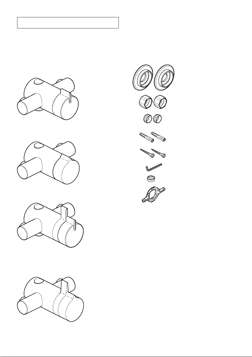
PACK CONTENTS
Tick the appropriate boxes to familiarise yourself
with the part names and to conrm that all of the
parts are included.
Documentation
q 1 x Guarantee Registration Document
q 1 x Installation Template
Exposed Thermostatic Mixers
q 1 x Thermostatic Mixing Valve
Mira Minilite EV or
Mira Minilite Eco EV
Mira Moto EV
Component Pack
q 2 x Concealing Plates
q 2 x Compression Nuts
q 2 x Olives
q 2 x Wall Plugs
q 2 x Fixing Screws
q 1 x 2.5 mm Hexagonal Key
q 1 x Flow Regulator (refer to
section: ‘Flow Regulators’)
q 1 x ‘O’ Key
Mira Miniduo EV or
Mira Miniduo with adjustable elbows
Mira Miniduo with Eco Showerhead EV
Mira Pace EV
Mira Pace with adjustable elbows
Mira Pace with Eco Showerhead EV
4

Built-in Thermostatic Mixers
q 1 x Thermostatic Mixing Valve
Mira Minilite BIV or
Mira Minilite Eco BIV
Mira Miniduo BIV or
Mira Miniduo with Eco Showerhead BIV or
Mira Miniduo with Eco Showerhead BIR
Documentation
q 1 x Guarantee Registration Document
q 1 x Cardboard Building-in Shroud
Component Pack
q 3 x Compression Nuts
q 3 x Olives
q 5 x Wall Plugs
q 5 x Fixing Screws
q 1 x 2.5 mm Hexagonal Key
oror
q 1 x Flow Regulator (refer to
section: ‘Flow Regulators’)
q 1 x ‘O’ Key
Mira Pace BIV
q 1 x Concealing Plate
Assembly
or
q 1 x RAC Assembly
5

Valve Combinations
These thermostatic mixers are available with various shower ttings and water saving features, refer to
the table below to identify your mixer valve combination:
Mixer Valve
Moto EV /
Minilite EV
Pace EV /
Miniduo EV
Minilite BIV L14A 12 L/Min Natural
Minilite Eco EV L14A 6 L/Min Black
Minilite Eco BIV L14A 6 L/Min Black
Miniduo BIV L98B
Pace with Eco
Showerhead EV
Miniduo with Eco
Showerhead EV
Miniduo with Eco
Showerhead BIV
Miniduo with Eco
Showerhead BIR
Shower
Fittings
L14A 12 L/Min Red
L98B 12 L/Min Red
L98B with Eco
Showerhead
L98B with Eco
Showerhead
L98B with Eco
Showerhead
Eco BIR
Showerhead
Flow Rate Colour Comments
12 L/Min Natural
7.0 L/Min Olive Green
7.0 L/Min Olive Green
7.0 L/Min Olive Green
7.3 L/Min
Bright
Green
Flow Regulator
Supplied in the component pack, designed to
be tted in the shower valve outlet
Supplied in the component pack, designed to
be tted in the shower valve outlet
Supplied in the component pack, designed
to be tted between the shower hose and
RAC assembly
Factory tted in the shower valve outlet
(optional 8 L/Min (white/natural) flow
regulator supplied separately in the
component pack)
Factory tted in the RAC assembly (optional
8 L/Min (white/natural) flow regulator
supplied separately in the component pack)
Supplied in the component pack, designed
to be tted between the shower hose and
RAC assemblyPace BIV L14D
Supplied in the component pack, designed
to be tted between the shower hose and
shower valve outlet
Supplied in the component pack, designed
to be tted between the shower hose and
shower valve outlet
Supplied in the component pack, designed
to be tted between the shower hose and
RAC assembly
Supplied with the Eco BIR shower head,
designed to be tted between the wall plate
and inlet nipple
Flow regulators are supplied for installation on high pressure systems (above 0.5 bar).
For gravity fed or other low pressure systems do not t the ow regulator.
The Mira Minilite Eco has a ow regulator factory tted in the shower valve outlet or RAC assembly,
on older combination boiler systems it may be necessary to replace this 6 L/Min ow regulator with the
8 L/Min ow regulator (supplied), in order to achieve the minimum ow rate required to ignite and run
the boiler.
Important! The tting of anyow regulator to Pace and Miniduo models will invalidate TMV2
compliance due to the minimum ow rate requirements. Do not t ow regulators in TMV2
applications to these models.
For further information on how and where to t the ow regulator, refer to section: ‘Flow Regulators’.
6
SPECIFICATIONS
45
For Type 2 Valves, the supply conditions specied
in section: ‘Type 2 Valves - Application’ take
precedence over the operating parameters which
follow.
Pressures
• Max Static Pressure: 10 Bar.
• Max Maintained Pressure: 5 Bar.
• Min Maintained Pressure (Gravity System):
0.1 Bar (0.5 Bar for models with Eco
Showerhead). (0.1 bar = 1 Metre head from
cold tank base to showerhead outlet).
Note! For gravity fed or other low pressure
systems (0.5 bar or below) do not t the outlet
ow regulator (where applicable).
• For optimum performance supplies should be
nominally equal.
Temperatures
• Factory Pre-set (Blend) Shower: 41°C.
• Optimum Thermostatic Control Range: 35°C
to 43°C (achieved with supplies of 15°C cold,
65°C hot and nominally equal pressures).
• Recommended Hot Supply: 60°C to 65°C
Note! The mixing valve can operate at
higher temperatures for short periods without
damage, however this could detrimentally
affect thermostatic performance. For safety
and performance reasons it is recommended
that the maximum hot water temperature is
limited to 65°C.
• Cold Water Range: up to 25°C.
• Minimum Recommended Differential between
Hot Supply and Outlet Temperature: 12°C.
Thermostatic Shut-down
• For safety and comfort the thermostat will
shut off the mixing valve within 2 Seconds if
either supply fails (achieved only if the blend
temperature has a minimum differential of
12°C from either supply temperature).
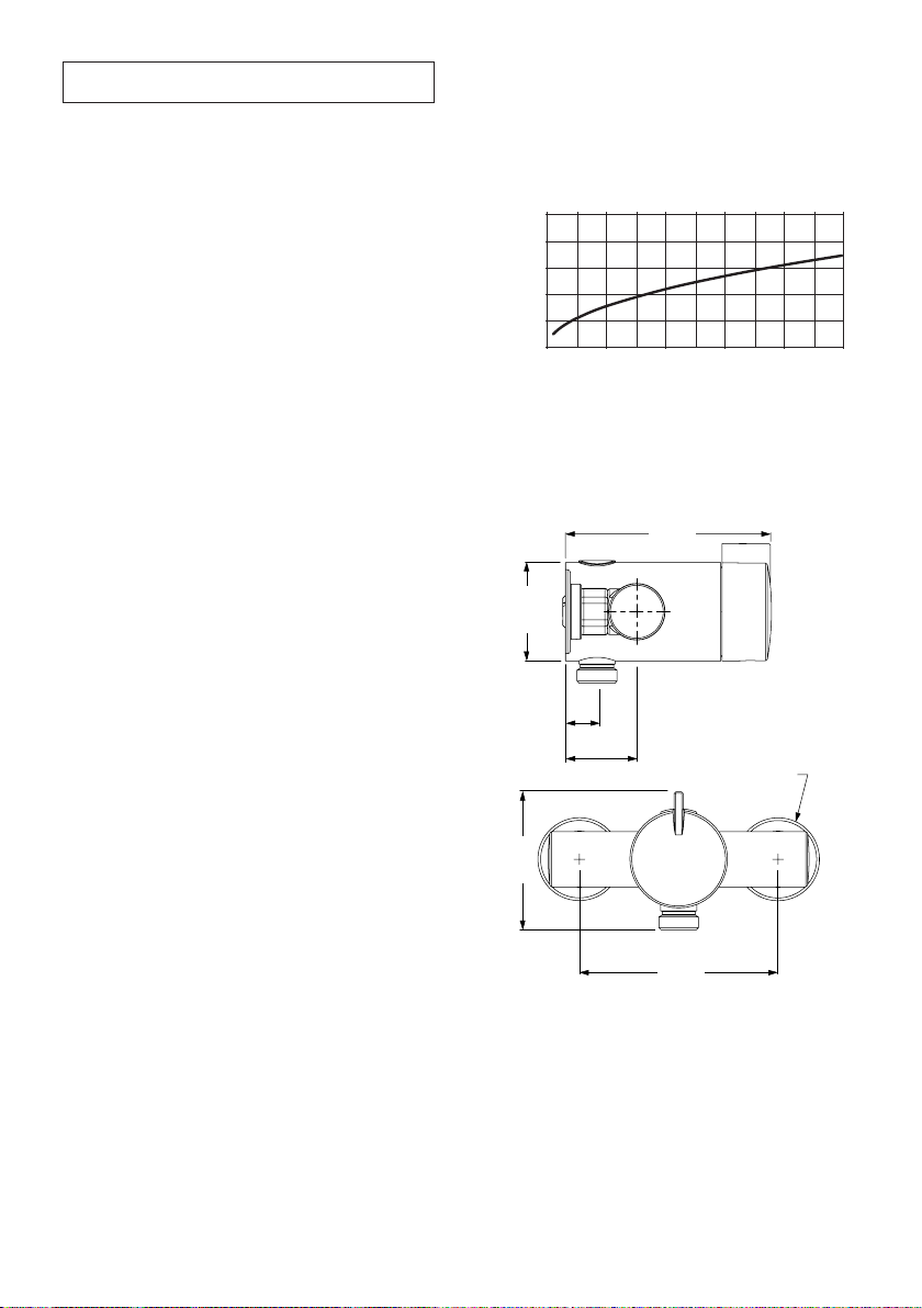
Flow Rates
Typical Flow Rates.
Mira Miniduo with Mira L98B Shower Fittings:
50
40
30
20
10
Flow Rate (L/Min)
0
0.5 1.5 2.5 3.5 4.5
01 23
Supply Pressure (bar)
Dimensions
(All dimension in millimetres)
Moto, Minilite and Minilite Eco EV
113
Ø54
17
39
Ø46
76.5
110
See Note! below
Connections
• Inlets: 15 mm Compression.
• Outlet: ½” BSP Flat Face / 15 mm
Compression
• Standard connections are: hot - left, cold -
right, outlet - bottom (EV models), top (BIV
and BIR models).
7
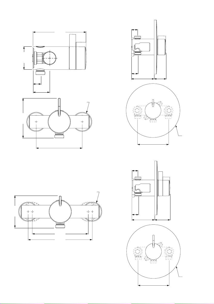
Pace, Pace with Eco Showerhead, Miniduo and
Miniduo with Eco Showerhead EV
125
Ø54
17
39
Ø46
95
110
See Note! below
Note! If you are retro-tting your mixing valve onto
existing pipework, an Adjustable Elbow Pack is
available if required, refer to section: ‘Accessories’.
Miniduo and Pace with Adjustable Elbows
Minilite and Minilite Eco BIV
20
21
56-76 39-59
Ø183
103
Pace, Miniduo BIV and Miniduo with Eco
Showerhead BIV / BIR
20
76.5
133
153
Pipe Centres at extremes of elbow adjustment
Ø46
21
56-76 53-73
Ø183
103
8
INSTALLATION
Suitable Plumbing Systems
Gravity Fed:
The thermostatic mixer must be fed from a cold
water cistern (usually tted in the loft space) and
a hot water cylinder (usually tted in the airing
cupboard) providing nominally equal pressures.
Mains Pressurised Instantaneous Hot Water
System (Combination Boiler):
The thermostatic mixer can be installed with
systems of this type with balanced pressures.
(Recommended Minimum Maintained Pressure:
1.0 Bar).
Note! On combination boiler systems we
recommend that the thermostatic mixer is
operated in the maximum ow position in order to
achieve the minimum ow rate required to ignite
and run the boiler.
Unvented Mains Pressure System:
The thermostatic mixer can be installed with an
unvented, stored hot water system.
Pumped System:
The thermostatic mixer can be installed with an
inlet pump (twin impeller). The pump must be
installed in a suitable location and in accordance
with its instructions.
3. Isolating valves must be installed close to the
Mixer for ease of maintenance.
4. Pipework must be rigidly supported and avoid
any strain on the connections.
5. Pipework dead-legs should be kept to a
minimum.
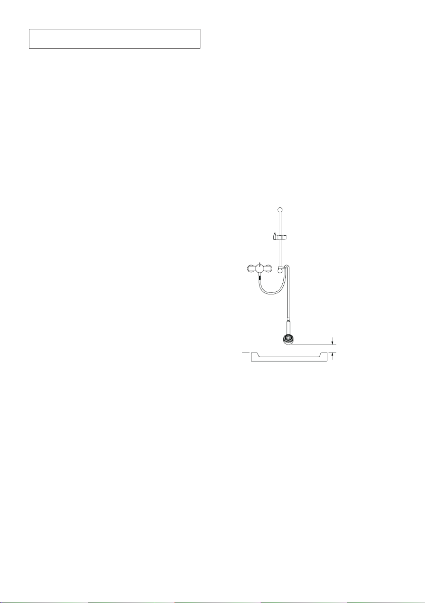
6. Decide on a suitable position for the Mixer.
The position of the Mixer and the Shower
Fittings must provide a minimum gap of 25 mm
between the spill-over level of the shower tray/
bath and the showerhead (refer to illustration).
This is to prevent back-siphonage. For further
information on the installation of your Shower
Fittings, refer to the Fittings Installation and
User Guide.
Note! Only use Shower Fittings recommended
by the manufacturer or supplier.
25 mm
Spill Over
Level
General
Installation must be carried out in accordance
with these instructions, and must be conducted by
designated, qualied and competent personnel.
The installation must comply with the “Water
Supply Regulations 1999 (Water Fittings)” or any
particular regulations and practices, specied by
the local water company or water undertakers.
Note! Make sure that all site requirements
correspond to the information given in section:
‘Specications’. For Type 2 Valves see also
supply conditions in section: ‘Type 2 Valves’.
1. The Mixer must not be installed in an area
where it may freeze.
2. For stud partitions alternative xings may be
required.
9
Exposed Thermostatic Mixers
For Built-in Thermostatic Mixers go to section:
‘Installation, Built-in Thermostatic Mixers’.
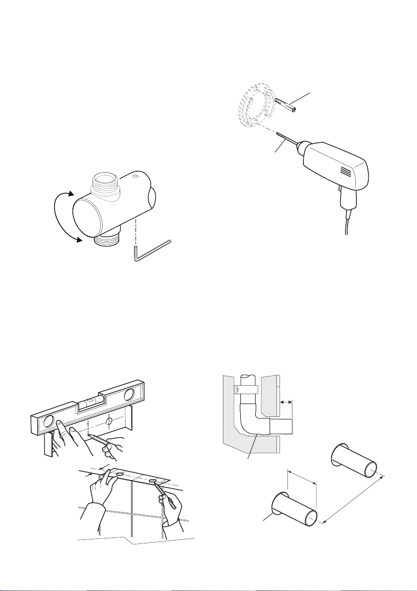
1. The thermostatic mixer can be installed with
rear, rising or falling supply inlets. Decide
on the most appropriate method for your
installation, and if necessary, loosen the
grubscrews and rotate the inlet elbows to
suit.
Important! Make sure that the elbows are
pushed fully onto the mixer before tightening
the grubscrews, do not overtighten.
2. Use the installation template to mark the
positions of the holes for the backplate and
the pipe centres.
For rising or falling supplies the pipe positions
should be set 39 mm from the centre of pipe
to the nished wall at 110 mm centres.
Note! If you are retro-tting your mixing valve
onto existing pipework, an Adjustable Elbow
Pack is available if required, refer to section:
‘Accessories’.
3. For solid walls drill the holes for the backplate
with a 6 mm drill and insert the wall plugs
(supplied). For other types of wall structure
alternative fixings may be required (not
supplied).
Wall Plug
6 mm Drill
4. For Rear Entry Supplies Only:
a) Drill the holes for the supply pipes at
110 mm centres.
Note! Recess the inlet holes Ø19 mm x
2 mm deep to allow for the concealing
plates.
5. Fit the supply pipework: Hot - Left, Cold
- Right. The inlet pipework should extend
23 mm from the nished wall surface.
Note! If it is not possible to install the
mixer with this pipework conguration follow
instruction 6.
39 mm
Recess Ø19 mm
x 2 mm deep
10
Elbow
23 mm from nished
wall surface
COLD
23 mm
HOT
110 mm
 Loading...