

Page 1
1
These instructions must be left with the user
Installation Guide
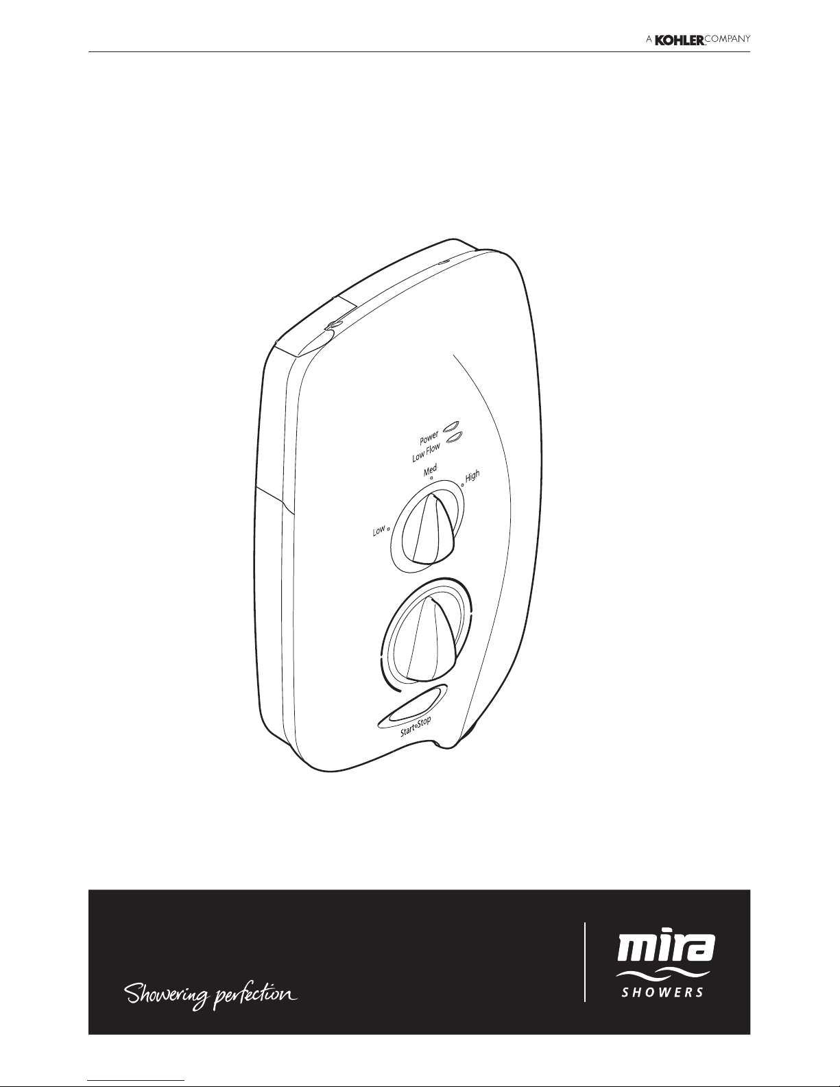
Mira Sport
7.5, 9.0 & 9.8 kW
Page 2

2
If you experience any difculty with the installation or operation of your new Electric
Shower, please refer to ‘Fault Diagnosis’, before contacting Kohler Mira Ltd. Our
telephone and fax numbers can be found on the back cover of this guide.
CONTENTS
Introduction .............................................................................................3
Guarantee ............................................................................................3
Patents and Design Registration ..........................................................3
Important Safety Information .................................................................4
Pack Contents Checklist ........................................................................5
Wiring Diagram ........................................................................................ 6
Specications .......................................................................................... 7
Plumbing ..............................................................................................7
Electrical ............................................................................................... 7
Dimensions ...........................................................................................7
Installation Requirements ......................................................................8
Plumbing ..............................................................................................8
Electrical ............................................................................................. 10
Installation ............................................................................................. 11
Commissioning .....................................................................................13
User Instructions ................................................................................... 15
User Safety Information ........................................................................ 17
Fault Diagnosis ......................................................................................19
User Maintenance ..................................................................................23
Cleaning .............................................................................................23
De-scaling the Showerhead ...............................................................23
Servicing ................................................................................................24
Inlet Filter - Cleaning/Renewing .........................................................24
Spare Parts ............................................................................................25
Accessories ...........................................................................................27
Customer Service .................................................................................. 28
Page 3
3
INTRODUCTION
Thank you for purchasing a quality Mira product. To enjoy the full potential of your
new product, please take time to read this guide thoroughly. Having done so, keep
it handy for future reference.
The Mira Sport is an electric shower with separate controls for power selection and
temperature/ow adjustment. A unique ow regulator stabilises temperature changes
caused by water pressure uctuations. These can result from taps being turned on
or off or toilets being ushed. Individual lights indicate "POWER" and "LOW FLOW".
Mira Sport models covered by this guide:
Product Model Number Colour
Mira Sport 7.5 J95A White/Chrome
Mira Sport 9.0 J95B/J95V White/Chrome & Chrome
Mira Sport 9.8 J95C/J95W White/Chrome & Chrome
Guarantee
For domestic installations, Mira Showers guarantee the Mira Sport against any
defect in materials or workmanship for a period of 2 years from the date of purchase
(shower ttings for one year).
For non-domestic installations, Mira Showers guarantee the Mira Sport against
any defect in materials or workmanship for a period of 1 years from the date of
purchase.
For Terms and Conditions refer to the back cover of this guide.
Patents and Design Registration
Design Registration: 000373543-002-004
Patents: GB: 2 341 667
Ireland: 82835
Patent Applications: UK: 2 427 460, 2 432 201
Ireland: 2006/0462, 2006/0818
Page 4

4
IMPORTANT SAFETY INFORMATION
WARNING - This shower can deliver scalding temperatures if not operated,
installed or maintained in accordance with the instructions, warnings and
cautions contained in this guide and on or inside the appliance.
TO REDUCE THE RISK OF FIRE, ELECTRIC SHOCK OR INJURY:
1. Installation of this shower must be carried out in accordance with these
instructions by qualied, competent personnel.
2. Isolate the electrical and water supplies before commencing installation. The
electricity must be isolated at the consumer unit and the appropriate circuit
fuse removed, if applicable. Mains connections are exposed when the cover
is removed.
3. DO NOT install the shower in areas with high humidity and temperature (i.e.
steam rooms and saunas).
4. DO NOT install the shower where it may be exposed to freezing conditions.
Ensure that any pipework that could become frozen is properly insulated.
5. DO NOT switch the shower on if there is a possibility that the water in the
shower is frozen.
6. DO NOT switch the shower on if water starts leaking from the shower case.
Isolate the electrical supply to the shower immediately.
7. DO NOT connect the outlet of the shower to any tap, control valve, trigger
handset or showerhead other than those specied for use with this shower.
Only Kohler Mira recommended accessories should be used.
8. The water supplies to this product must be isolated if the product is not to be
used for a long period of time. If the product or pipework is at risk of freezing
during this period they should also be drained of water.
9. DO NOT perform any unspecied modications to the shower or it’s accessories.
When servicing only use Genuine Kohler Mira replacement parts.
10. If the shower is dismantled during installation or servicing then upon completion
the product must be inspected to ensure all electrical connections are tight and
that there are no leaks.
11. Read all installation instructions before installing this shower.
12. Upon completion of the installation, make sure that the user is familiar with the
operation of the shower, and leave this guide with the owner.
Page 5
5
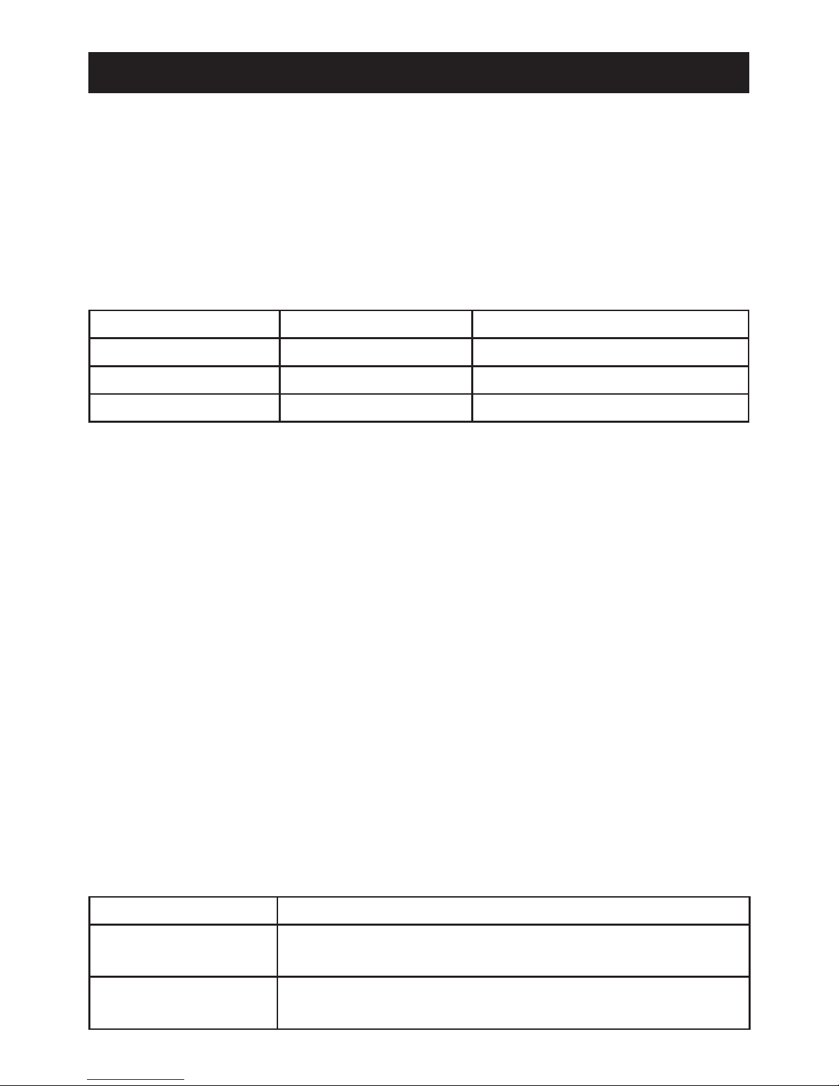
PACK CONTENTS CHECKLIST
Tick the appropriate boxes to familiarize yourself with the part names and to
conrm that the parts are included.
q 3 x Wall Plugs
q 1 x Compression Nut
q 3 x Fixing Screws
q 2 x Case Inserts
q 1 x Olive
q 1 x Mira Sport 7.5, 9.0 or 9.8
Documentation
q 1 x Installation Template
q 1 x Installer Checklist
q 1 x Guarantee Card
Page 6
6
BROWN
BROWN
BROWN
BROWN
BLACK
BLACK
BLACK
BLUE
BLUE
GREEN
GREEN
BLACK
RED
RED
RED
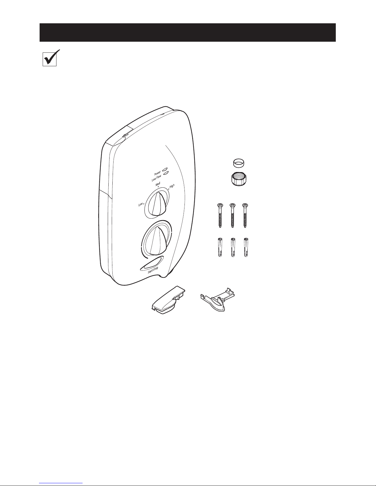
Thermal Cutout
Dual Disc
L
Solenoid
Valve
Pressure/Power
Selector Switch
Low Flow
Neon
Power On
Neon
N
E
Tank Connection
Inlet Connector
Internal Wiring Diagram
Load
WIRING DIAGRAM
START/STOP
Page 7
7
SPECIFICATIONS
European Conformity Information
Mira Sport range of showers complies with the following European directives:
2006/95/EC Low Voltage Directive, 2004/108/EC EMC Directive.
Mira Sport range of showers are high power appliance and are subject to
conditional connection. If the main electrical supply fuse is rated less than 80
Amps, the local electricity supply company must be contacted to conrm if the
electrical supply is adequate.
Mira Sport range of showers complies with the requirements of the UK’s water
regulations.
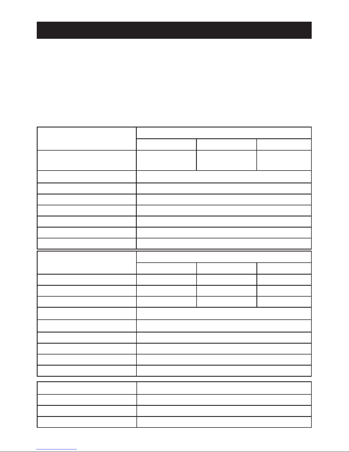
Dimensions
Height 340 mm
Width 204 mm
Depth 80 mm
Electrical
Variant
Sport 7.5 Sport 9.0 Sport 9.8
Nominal Power at 230 V ac 6.9 kW 8.3 kW 9.0 kW
Nominal Power at 240 V ac 7.5 kW 9.0 kW 9.8 kW
Recommended MCB Rating 40 A 40 A 45 A
Maximum Supply Cable Size 16 mm²
Recommended RCD Rating 30 mA tripping current
Recommended Isolator Switch 45 A double-pole with 3 mm contact separation
Appliance Sealing Rating IP X4 - Suitable for installation in Zone 1
Maximum Ambient Temperature 30°C
Minimum Ambient Temperature 2°C
Plumbing
Variant
Sport 7.5 Sport 9.0 Sport 9.8
Minimum Dynamic Pressure 70 kPa
(0.7 bar)
70 kPa
(0.7 bar)
70 kPa
(0.7 bar)
Maximum Static Pressure 1000 kPa (10 bar)
Minimum Static Pressure 20 kPa (0.2 bar)
Maximum Inlet Temperature 30°C
Minimum Inlet Temperature 2°C
Inlet Connection 1/2” BSP Male / 15 mm Compression Fitting
Maximum Water Hardness 200 ppm CaCO
3
Outlet Connection 1/2” BSP Male
Page 8

8
Please read the Important Safety Information and specications sections at
the front of this guide, and the requirements detailed in this section before
installing the shower.
WARNING - TO REDUCE THE RISK OF FIRE, ELECTRIC SHOCK OR INJURY:
Plumbing
1. The plumbing installation must comply with all national or local water regulations
and all relevant building regulations, or any particular regulation or practice
specied by the local water supply company.
2. Do not install the product in a position in which service access is limited.
3. Decide on a suitable position for the shower (minimum distance of 200 mm from
the ceiling to allow for cover t and removal).
4. The position of the shower and shower ttings must provide a minimum gap of
25 mm between the showerhead and the spill over level of any bath, shower
tray or basin and a minimum gap of 30 mm between the showerhead and the
spill over level of any toilet, bidet or other appliance with a Fluid Category 5
backow risk (see diagram on page 9).
5. The shower is suitable for installation within the shower area and is tted with
a pressure relief valve. It must be positioned over a water catchment area with
the controls at a convenient height for the user.
6. The shower must be tted to a waterproof at and even wall surface.
7. DO NOT t the shower to the wall and tile up to the case.
8. DO NOT seal the gap between the shower and the wall surface.
9. The showerhead should be positioned so that it discharges down the centre
line of the bath or across the opening of a shower cubicle.
10. The showerhead must be directed away from the shower unit, during normal
use the showerhead must not spray directly on to the shower unit.
11. DO NOT apply excessive force to plumbing connections; always provide
mechanical support when making plumbing connections. Any soldered joints
should be made before connecting the shower.
12. This shower is not designed to be plumbed directly from the rear. For rear-entry
supply, add an elbow to the supply pipe and connect as a rising or a falling supply.
13. If pipework and/or electrical cables enter the shower from the rear through a
hole in the wall provision must be made to prevent water ingress back into the
wall structure.
14. Only use the inlet connector supplied with the shower. DO NOT use any other
type of tting.
INSTALLATION REQUIREMENTS
Page 9
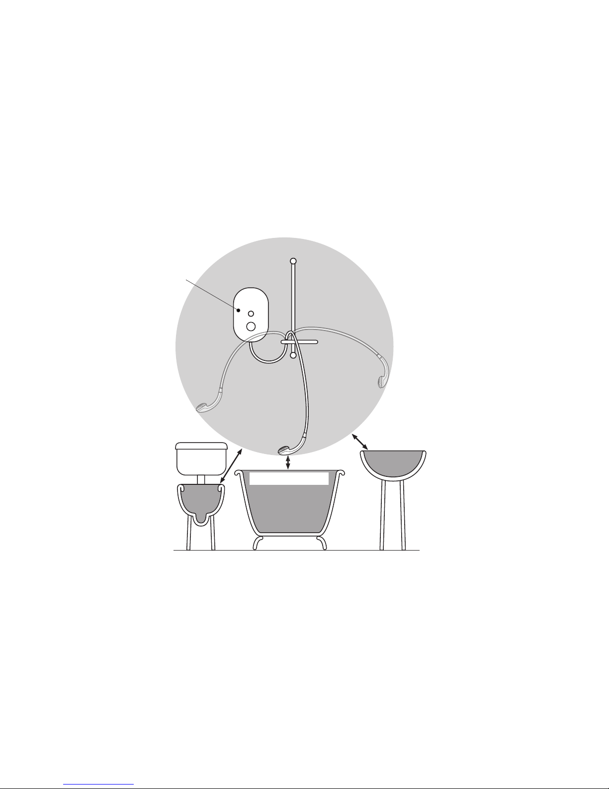
9
Hose Retaining Ring tted and shower ttings xed at a suitable height preventing
dirty water backow.
Note! There will be occasions when the hose retaining ring will not provide a suitable
solution for Fluid Category 3 installations, in these instances an outlet double
checkvalve must be tted, this will increase the required supply pressure typically
by 10kPa (0.1 bar). Double checkvalves tted in the inlet supply to the appliance
cause a pressure build up, which could exceed the maximum static inlet pressure
for the appliance and must not be tted. For Fluid category 5 double checkvalves
are not suitable.
Zone of
Backow Risk
30 mm
Minimum
Toilet or Bidet
FC5
Hand Basin
FC3
Bath or Shower
Tray FC3
Electric
Shower
25 mm
Minimum
25 mm Minimum
15. A full bore/non restrictive servicing valve must be tted in a readily accessible
position adjacent to the shower to facilitate maintenance of the shower.
DO NOT use a valve with a loose washer plate (jumper) as this can lead to a
build up of static pressure.
16. A water treatment device should be installed where the water hardness may
exceed 200 ppm. Malfunctions caused by excessive limescale formation are
not covered by this shower’s guarantee (see back page for details).
17. The installation must not cause the hose to be sharply kinked during normal
use.
18. DO NOT perform the electrical installation until the plumbing has been
completed and checked for leaks.
Page 10

10
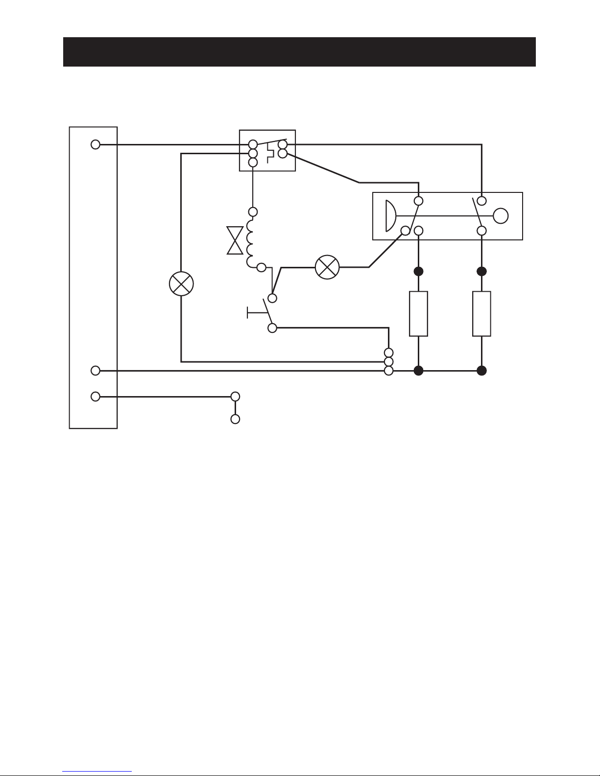
Consumer Unit
Double-pole Isolating
Switch
WARNING - TO REDUCE THE RISK OF FIRE, ELECTRIC SHOCK OR INJURY:
Electrical
1. The electrical installation must comply with BS 7671 (commonly referred to as
the IEE Wiring Regulations) and all relevant building regulations, or any particular
regulation or practice specied by the local electricity supply company.
2. Ensure that all circuit protection devices, switches and cabling is adequate
for the rated current of the shower and that the rating of the electricity supply
company fuse and the consumer unit are adequate for the additional demand.
3. The shower must be earthed. Ensure any supplementary bonding complies
with the relevant regulations.
4. This shower is intended to be permanently connected to the xed electrical wiring
of the mains system. A separate supply must be provided from the consumer
unit to the shower.
5. DO NOT supply any other electrical equipment including extractor fans or pumps
via this product.
6. This shower must be provided with means for local disconnection that is
incorporated into the xed wiring in accordance with the relevant local wiring
regulations. This must be a double pole switch, which has at least 3 mm contact
separation in each pole. The switch can be a ceiling mounted pull-cord type within
the shower room or a wall mounted switch tted in the applicable zone area.
7. A 30mA Residual Current Device (RCD) is recommended to be tted in the
circuit to the shower.
8. DO NOT apply excessive force to the terminal block.
9. All electrical connections should be checked for tightness to prevent overheating
before switching on the electrical supply.
10. DO NOT switch on the electrical supply until the plumbing has been completed
and checked for leaks.
Plumbing and Electrical Schematic
Page 11

11
INSTALLATION
Read the section “Important Safety Information” rst
Electrical supply is turned
off at the mains.
200 mm minimum gap
from ceiling.
Remove three screws.
INSTALLATION TEMPLATE
Mira Sport
Attention Installer
Caution! Do not drill into
buried cables or pipes.
Drill and plug* the three
holes using template.
Remove cover and
determine supply pipe
position.
For back inlet use soldered
elbow.
Do not trap green wire.
Fix appliance to wall. Flush a minimum of 10
litres through pipework.
* Alternative xings for some wall structures are not supplied.
1. 2.
200 mm
3.
4. 5. 6.
7. 8. 9.
Page 12

12
Connect supply pipe. Do not
overtighten!
Feed cable into Case. Fit Earth
sleeve (not supplied) and strip
insulation.
Do not twist cable cores.
Firmly connect the conductors.
Do not exert strain on the terminal
block.
Make sure wires are clear of all
mounting holes.
Ret the Service Tunnel and Cover.
Make sure they t correctly.
Do not overtighten screws.
Do not use alternative screws to
secure the Cover. This can cause
internal damage to the appliance.
Do not seal around the back of
appliance.
L = BROWN
E = GREEN
N = BLUE
10. 11.
12. 13.
14. 15.
Important! Make sure that the inlet earth
wire is routed as shown. Failure to do so
may cause product malfunction.
Page 13

13
Before carrying out the commissioning procedure install the Shower Fittings,
refer to the Shower Fittings Installation and User Guide.
If you are unsure how an electric shower works, please read through the User
Instructions section before continuing.
COMMISSIONING
Electrical supply is turned
off at the mains.
Turn control to full cold. Turn water supply fully
on.
Check for water leaks. Set control to LOW. Switch on electrical
supply.
Push START button.
COLD
Water will be at full force and
at a cool temperature.
Turn control slowly.
Temperature remains cool
and ow is reduced.
Turn control to full cold. Set control to MEDIUM.
_
+
The temperature will rise
slightly.
0 - 5 secs
5 - 10 secs
1. 2. 3.
4. 5. 6.
7. 8. 9.
10. 11. 12.
Page 14

14
Note! A slight hissing sound may be heard from the Mira Sport during operation.
High mains water pressure and high shower temperatures will affect the tone. This
is quite normal in use.
Set control to HIGH.
_
+
The temperature will rise further.
Adjust temperature as required.
Flow rate will adjust automatically.
Press STOP and isolate power.
The shower will purge water from
its tank for a few seconds.
Residual water may drain over a
few minutes.
5 - 10 secs
0 - 5 secs
13. 14.
15. 16.
17. 18.
Page 15

15
USER INSTRUCTIONS
The warmer the shower, the lower the
ow rate and vice versa.
_
+
COLD
_
+
_
+
Hot water is produced by passing cold
water through a heating tank.
The shower has three heater settings.
How Your Electric Shower Works
Page 16

16
_
+
Water inlet pressure uctuations due to other draw offs (e.g. ushing toilet) will cause
the showering temperature to increase.
*
*
*
_
+
For a cold shower select LOW
For a summer warm shower select MEDIUM
For a winter warm shower select HIGH
Adjust the temperature as required
The ow rate will adjust automatically
The Effect of Seasonal Changes
The Effect of Other Water Devices
Showering temperature
will stabilize to within 6°C
band if other outlets are
opened whilst showering,
providing the minimum
pressure does not fall
below 70 kPa (0.7 bar).
Selected
Showering
Temperature
Example of how shower temperature
stabilizes due to pressure changes.
Page 17

17
USER SAFETY INFORMATION
1. Make sure that you fully understand how
to operate this shower before use, read
all operating instructions and retain this
guide for future reference.
2. This shower is not intended for use
by persons (including children) with
reduced physical, sensory or mental
capabilities, or lack of experience and
knowledge, unless they have been given
supervision or instruction concerning
the use of the shower by a person
responsible for their safety.
3. Children should be supervised to ensure
that they do not play with the shower.
4. DO NOT switch the shower on if there is
a possibility that the water in the shower
is frozen.
5. DO NOT switch the shower on if water
leaks from the shower unit. Isolate
the electrical supply to the shower
immediately.
6. DO NOT switch the shower on if
the case appears to be damaged or
incorrectly tted. Isolate the electrical
supply to the shower immediately.
7. Switch off the appliance at electrical
isolating switch when not in use. This is
for safety and is recommended with all
electrical appliances.
8. DO NOT connect the outlet of the
shower to any tap, control valve, trigger
handset or showerhead other than those
specied for use with this shower. Only
Kohler Mira recommended accessories
should be used.
9. Always check the water temperature
before entering the shower. Sunburn
or skin conditions can increase your
WARNING - THIS SHOWER CAN DELIVER SCALDING TEMPERATURES IF
NOT OPERATED, INSTALLED OR MAINTAINED IN ACCORDANCE WITH THE
INSTRUCTIONS, WARNINGS AND CAUTIONS CONTAINED IN THIS GUIDE AND
ON OR INSIDE THE APPLIANCE.
To reduce the risk of re, electric shock or injury:
sensitivity to hot water. Make sure
that you set the shower to a cooler
temperature.
10. DO NOT operate the temperature
control rapidly, allow 10 – 15 seconds for
the temperature to stabilise before use.
11. Care is required if the shower is turned
off and back on during showering as
this may result in unstable temperature.
Ensure temperature has stabilised
before re-using shower.
12. The showerhead must be de-scaled
regularly, refer to the user maintenance
section towards the rear of this guide
for details.
13. The shower hose must be checked
regularly and replaced if damaged, refer
to the user maintenance section towards
the rear of this guide for details.
14. DO NOT store bathroom items on top of
the shower unit (i.e. shampoo or shower
gel containers).
15. The shower must be operated and
maintained in accordance with the
requirements of this guide.
16. If any of the following conditions occur,
isolate the electricity and water supplies
and contact Kohler Mira Customer
Service.
• If the case is damaged or the cover
is not correctly tted and water has
entered the shower case.
• If the shower begins to make an
odd noise, smell or smoke.
• If the shower shows signs of a
distinct change in performance
indicating a need for maintenance.
Page 18

18
A small amount of water may
continue to drain over a few
minutes.
Press STOP button. Shower will
continue to run for a few seconds
before stopping.
_
+
Switch on electrical supply. Press START button.
Set to desired position.
Allow 10-15 seconds for any temperature adjustments to reach the
handset.
_
+
Check water temperature before
entering shower.
Using Your Shower
Read the section “User Safety Information” rst.
1. 2.
3. 4.
6. 7.
5.
Page 19

19
FAULT DIAGNOSIS
The trouble shooting information tabled below gives details on probable causes and
remedies should difculties be encountered whilst the shower is in operation.
Warning! There are no user serviceable components beneath the cover of the
appliance. Only a competent trades person should remove the front cover!
Symptom
Power
Light
Low
Flow
Light
Heater
Low/
Med/
High
Probable Cause Possible Remedy
Appliance
fails to
operate.
OFF
OFF
OFF
OFF
Any
Any
Electrical supply
isolated at double
pole switch.
Fuse blown or
MCB/RCD tripped,
indicating possible
electrical fault.
Switch on electrical
supply via the
pullcord or wall
mounted switch.
Renew the fuse
or reset the MCB/
RCD. If fault
persists, contact
your installer.
Shower
cycles from
hot to cold.
ON
ON
ON
ON
ON
OFF
Med/
High
Med/
High
Med/
High
Handset blocked.
Water pressure
below minimum
required for
appliance
operation.
Temperature dial or
heater setting too
high.
Remove and clean.
Make sure incoming
mains water
stopcock and/or
appliance isolating
valve is fully turned
on.
Turn the heater
selector knob to
medium or turn
the temperature
control until a
cooler temperature
is achieved.
Page 20

20
Symptom
Power
Light
Low
Flow
Light
Heater
Low/
Med/
High
Probable Cause Possible Remedy
Unable to
select a
cool enough
shower.
ON OFF High Due to the rise in
mains water supply
temperature, the
Heater setting may
be too high.
Turn the heater
selector knob to
medium and adjust
the temperature
control until a
suitable temperature
is achieved.
Handset
dripping.
OFF
OFF
OFF
OFF
Any
Any
Insufficient water
supply pressure for
shut off.
Flow Valve faulty.
Min static pressure
to ensure shut off
and prevent dripping
is 20 kPa (0.2 bar).
Note! If other
appliances are
operating, static
pressure may
drop below 20
kPa (0.2 bar).
Contact local water
company. Renew
Flow Valve.
Replace.
Low or no
ow.
ON ON Any Water supply
pipework or inlet
lter restricted by a
blockage or partial
blockage.
Insufficient water
supply pressure/
ow for operation.
Flush supply pipe.
Clean Inlet Filter.
Contact local water
company. Supply
pressure must be a
minimum of 70 kPa
(0.7 bar).
Note! If other
appliances are
operating, pressure
may drop below
70 kPa (0.7 bar).
(cont....)
Page 21

21
Symptom
Power
Light
Low
Flow
Light
Heater
Low/
Med/
High
Probable Cause Possible Remedy
Low or no
ow.
(cont....)
ON
ON
ON
ON
ON
ON
OFF
OFF
OFF
OFF
Any
Any
Any
Any
Any
Other outlets (e.g.
toilet, garden hose,
washing machine,
etc.) drawing water
while the shower is
being used.
Handset blocked.
Service tunnel or
cover not fitted
correctly causing
Start/Stop button
not to operate.
Flow Valve faulty.
Heater Tank
excessively scaled.
Turn off other
appliances whilst
shower is in use.
Remove and clean.
Check case inserts
are cut and fitted
correctly. Check
services (electrical
or plumbing) are
not interfering with
location of service
tunnel or cover.
Replace.
Replace. In hard
water areas consider
the use of a water
softener.
Operation of
Temperature
Control
has little or
no effect
on water
temperature.
ON
ON
ON
ON
ON
OFF
OFF
OFF
Med/
High
Med/
High
Med/
High
Med/
High
Handset or Inlet
Filter blocked.
Flow Valve faulty.
Heater Tank failure.
Microswitch failure.
Remove and clean.
Replace.
Replace.
Replace.
Page 22

22
Symptom
Power
Light
Low
Flow
Light
Heater
Low/
Med/
High
Probable Cause Possible Remedy
No change in
temperature
between Low/
Medium/High
setting.
ON
ON
ON
OFF
Any
Any
Insufficient mains
water pressure.
Possible failure
of flow valve,
microswitch, or
heater tank.
Contact local water
company.
Use a suitable
continuity device to
check the continuity
of the microswitch
or heater tank and
replace parts as
necessary.
Water will not
turn off.
ON
ON
OFF
ON
Any
Any
Flow valve, solenoid,
or Start/Stop switch
faulty.
Supply pressure
below 20 kPa
(0.2 bar).
Replace as
necessary.
Contact local water
company. Check
mains water static
pressure.
Appliance
fails to
produce
hot water
when set
on Medium/
High Heater
Setting.
ON
ON
ON
ON
OFF
OFF
Med/
High
Med/
High
Med/
High
Insufficient water
supply.
Possible failure of
the microswitch or
thermal switch.
Heater tank failure.
Contact local water
company.
Use a suitable
continuity device to
check the continuity
of the microswitch
or heater tank and
replace parts as
necessary.
Replace.
Page 23

23
USER MAINTENANCE
There are no user serviceable
parts inside the shower. Only
qualified, competent personnel
should remove the front cover,
mains connections are exposed
when the cover is removed.
Switch the shower off at the isolator
switch before performing any user
maintenance or before cleaning
the shower.
DO NOT allow young children
to perform user maintenance
including cleaning of the shower.
Use your thumb or a
soft cloth to wipe any
limescale from the
soft nozzles
DO NOT use the showerhead to
clean the shower.
If the shower is not to be used for
a long period, the electrical supply
and water supply to the shower
should be isolated. If the shower
or pipework is at risk of freezing
during this period a qualified,
competent person should drain
them of water.
Unscrew the hose from
the showerhead and
the shower outlet.
Inspect the hose.
Cleaning
Many household cleaners contain abrasives and chemical substances, and should not
be used for cleaning plated or plastic ttings. These nishes should be cleaned with
a mild washing up detergent or soap solution, and then wiped dry using a soft cloth.
WARNING - TO REDUCE THE RISK OF FIRE, ELECTRIC SHOCK OR INJURY:
De-scaling the Showerhead
Important! Keeping the showerhead
clean and free from limescale will ensure
that your shower and showerhead
continue to perform to their maximum.
A blocked showerhead can restrict the
flow rate and may cause damage to
your shower
Inspecting the hose.
Important! The shower hose should
be inspected periodically for damage
or internal collapse, internal collapse
can restrict the flow rate from the
showerhead and may cause damage to
the shower. Remove the shower hose
from the shower, inspect and replace the
hose if necessary.
Page 24

24
Make sure that the electrical supply
is turned off at the mains and that the
water supply is fully turned off.
Remove the three screws and the
cover.
Inlet Filter - Cleaning/Renewing
Read the section “Important Safety Information” rst
Cover
Cover Retaining
Screw
Hold a wrench across the ats of the
metal connector. Unscrew the lter
using another wrench as shown. Clean
or renew the Filter as necessary. Ret
in reverse order making sure the Filter
is screwed fully home.
Do not overtighten! Make sure
plumbing connections are sealed
before restoring electricity supply.
Refit the cover making sure it is
correctly located. Do not overtighten
the screws.
Filter
SERVICING
WARNING
There are no user serviceable parts inside the shower.
Servicing of the shower must only be carried out by qualied, competent
personnel following the instructions provided in this guide and those provided
with any spare part.
Before replacing any parts, ensure that the underlying cause of the malfunction
has been resolved.
Page 25

25
SPARE PARTS
405.58 Inlet Connector Assembly
406.27 Inlet Filter (with 'O' seal tted)
416.38 Clamp Bracket (Inlet)
416.41 Thermal Switch
416.48 Latching Switch
416.51 Solenoid Coil
872.01 Microswitch N/O - 2 pin
872.28 Microswitch C/O - 3 pin
1563.500 Heater Tank 7.5 kW 240 V AC (6.85 kW 230 V AC)
1563.502 Heater Tank 9.0 kW 240 V AC (8.2 kW 230 V AC)
1563.504 Heater Tank 9.8 kW (9.0 kW 230 V AC)
1563.507 Flow Valve Assembly
1563.509 Switching Assembly
1563.511 Cover Assembly
1563.513 Screw Pack - components identied 'A'
1563.514 Low Flow Neon Assembly
1563.515 Power On Neon Assembly
1563.516 Outlet Connector
1563.517 Service Tunnel
1563.518 Component Pack - components identied 'B'
1563.519 Terminal Block Assembly 9.8 kW 240 V AC (9.0 kW 230 V AC) only
1563.520 Wire Pack (not shown)
1563.522 Cover Seal (not shown)
1695.017 Cover Assembly (Chrome)
1695.018 Service Tunnel (Chrome)
1695.019 Component Pack (Chrome) Not Shown
1695.026 Case Insert Chrome Top (Not Shown)
1695.027 Case Insert Chrome Bottom (Not Shown)
Note! Case inserts 1695.026 and 1695.027 adapted for chrome variants with top
or bottom service entry points are available on request.
Page 26

26
416.41
1563.502
1563.500
1563.504
1563.511
416.48
416.51
1563.514
1563.515
416.38
406.27
405.58
1563.517
1563.516
A
A
A
B
B
B
B
B
B
B
B
B
1563.507
1563.519
1563.509
872.28
872.01
Important! Push-t connectors must be assembled
back to back onto terminals of micro-switches.
A minimum air gap of 4 mm must be maintained
between the connectors after assembly.
4 mm MINIMUM
1695.017
1695.018
Page 27

27
ACCESSORIES
Genuine Mira accessories can be purchased direct from Customers Services (our contact details can
be found on the back cover of this guide) or from approved stockists or merchants.
Everclear Showerhead
White - 2.1616.030
Chrome - 2.1616.031
Mira's new Everclear range has
been specially designed for hard
water areas and reduces the risk
of lime scale build up.
Shower Seat
White - 2.1536.128
White/Chrome - 2.1536.129
For use in or out of the showering
area. Folds up when not in use.
Maximum User Weight - 127 kg
(20 stone) Note! Must be installed
onto a solid wall.
Premium Shower Seat
White/Chrome - 2.1731.001
Grey/Chrome - 2.1731.002
Stylish, slim-line and robust
shower seat for use in or outside
of the shower area. Folds up when
not in use. Maximum User Weight
- 150 kg (23.5 stone) Note! Must
be installed onto a solid wall.
Logic Showerhead Holder
White - 2.1605.149
White/Chrome - 2.1605.150
An alternative to the traditional
slide bar. Often a useful addition
when positioned for the smaller
members of the family.
Outlet Double Check Valve
(DCV-H)
Chrome - 1.0.110.55.1
An outlet double check valve,
designed to prevent the back ow
or back-siphonage of potentially
contaminated water, through
shower controls which are tted
with a exible shower hose as part
of the outlet shower tting.
Mira Standard Grab Bars
300 mm - 2.1605.070
450 mm - 2.1605.071
600 mm - 2.1605.072
Premium grade, highly polished,
stainless steel grab bars.
Note! Must be installed onto a
solid wall.
Page 28

28
Guarantee
Your product has the benefit of our manufacturer’s
guarantee which starts from the date of purchase.
To activate this guarantee, please return your completed
registration card, visit our website or free phone 0800
0731248 within 30 days of purchase (UK only).
Within the guarantee period we will resolve defects in
materials or workmanship, free of charge, by repairing or
replacing parts or product as we may choose.
This guarantee is in addition to your statutory rights
and is subject to the following conditions:
● The guarantee applies solely to the original installation
under normal use and to the original purchaser only.
The product must be installed and maintained in
accordance with the instructions given in this user
guide.
● Servicing must only be undertaken by us or our
appointed representative. Note! if a service visit
is required the product must be fully installed and
connected to services.
● Repair under this guarantee does not extend the original
expiry date. The guarantee on any replacement parts
or product ends at the original expiry date.
● For shower fi ttings or consumable items we reserve
the right to supply replacement parts only.
The guarantee does not cover:
● Call out charges for non product faults (such as
damage or performance issues arising from incorrect
installation, improper use, lack of maintenance, build up
of limescale, f rost damage, corrosion, system debris or
blocked fi lters) or where no fault has been found with
the product.
● Water or electrical supply, waste and isolation issues.
● Compensation for loss of use of the product or
consequential loss of any kind.
● Damage or defects caused if the product is repaired
or modifi ed by persons not authorised by us or our
appointed representative.
● Routine maintenance or replacement parts to comply
with the requirements of the TMV 2 or TMV 3 healthcare
schemes.
● Accidental or wilful damage.
● Products purchased ex-showroom display.
What to do if something goes wrong
If your product does not function correctly when you fi rst
use it, contact your installer to check that it is installed
and commissioned in accordance with the instructions in
this manual.
If this does not resolve the issue, contact
our Customer
Services Team who will offer you or your installer help
and advice.
If you experience problems, check in this manual to see if
simple home maintenance is required. If you require further
assistance call our Customer Services Team.
Extended Guarantees
A selection of protection plans are available that
enable you to cover repair bills for the life of your policy
(excludes Eire). Ring 01922 471763 for more details.
Helpdesk Service
Our Customer Services Team is comprehensively trained
and can offer help and advice, spare parts, accessories or
a service visit.
We will need you to have your model name or number,
power rating (if applicable) and date of purchase. As part of
our quality and training programme calls may be recorded
or monitored.
Mira Showers Website
(www.mirashowers.co.uk)
From our website you can register your guarantee,
download additional user guides, diagnose faults, purchase
our full range of accessories and popular spares, refer to
our FAQ’s and request a service visit.
Spares and Accessories
We maintain extensive stocks of genuine spares and
accessories and aim to provide support throughout the
product’s expected life.
Payment can be made by phone at time of order using
most major Credit or Debit cards and we aim to despatch
orders within 2 working days. Items purchased from us are
guaranteed for 12 months from date of purchase. For safety
reasons spares exposed to mains voltages should only be
fi tted by competent persons.
Returns – items can be returned within one month of date
of purchase, providing that they are in good condition and
the packaging is unopened. If you wish to return any items
please notify us in writing within seven days of receipt.
Service / Repairs
Our nationwide team of Service Technicians can carry out
service or repair work to your product within the guarantee
period and beyond. You have the assurance of a fully trained
Technician, genuine spare parts and a 12 month guarantee
on any chargeable work done.
Payment should be made directly to the Service Technician
who will accept most major Credit or Debit cards.
To Contact Us
UK
Telephone: 0844 571 5000
E-mail - Visit www.mirashowers.co.uk/contactus
Fax: 01242 282595
By Post: Mira Customer Services Dept, Cromwell Road,
Cheltenham, Gloucestershire, GL52 5EP
Eire
Telephone: 01 459 1344
E-mail: sales@modernplant.ie
Fax: Dublin 01 459 2329
By Post: Modern Plant Ltd (Dublin),
Otter House, Naas Road, Clondalkin, Dublin 22
Mira is a registered trade mark of
Kohler Mira Limited.
The company reserves the right to alter
product specifi cations without notice.
FM 14648
1060737-W2-G (1563) (J95A/B/C/V/W) © Kohler Mira Limited, January 2012
CUSTOMER SERVICE
 Loading...