

Mira Flight Shower Tray, Flight Shower Tray Riser, Flight Shower Tray Non-Riser User Manual
Page 1
Mira Flight Shower Tray
Riser and Non-Riser
These instructions must be left with the user
Installation and User Guide
1
Page 2

INTRODUCTION
Thank you for purchasing a quality product. To enjoy the full potential of your new
shower tray, please take time to read this guide thoroughly, and keep it handy for
future reference.
Important! The shower trays featured in this manual are available for use as riser
and non-riser products.
Mira Flight Shower Trays - are av ailable in various shapes and sizes with or without
upstands and are all supplied with an 85 mm top access waste and trap.
Mira Flight Riser Conversion Kit - comprises of adjustable legs, panels, panel
securing clips, corners and optional end pieces. Riser Conversion Kits are available
to purchase separately.
Mira Flight Offset Leg Adaptor Fittings Kit - for use with the Mira Flight Riser
Conversion Kit, the Offset Leg Adaptor allows the installation of pipework behind the
adjustable legs. Offset Leg Adaptor Fittings Kits are available to purchase separately
(refer to section: ‘Accessories’).
Mira Flight Upstand Tiling Strip - Upstand Tiling Strips are available to purchase
separately (refer to section: ‘Accessories’).
IMPORTANT INFORMATION
Important! The shower trays featured in this manual are available for use as
riser and non-riser products.
The shower waste can cope with a ow rate of up to 25 L/min, with a pipe length
of 3 m for 40 mm pipe and 4 m for 50 mm pipe, with a fall of between 18 and
90 mm/m. The ow rate will be reduced with the introduction of bends or T ttings
in the waste outlet pipe.
Carefully unpack and check the tray for colour, size, general acceptability and
compatibility with the shower enclosure and other bathroom furniture.
Check for transit damage and report any faults immediately to your supplier.
No claims for the above will be considered after installation.
Carefully remove all of the blue protective lm from the tray for inspection.
Caution! Additional protective coverings such as a dust sheet should then be
used to protect the tray from damage from falling objects.
Place the shower tray on a at surface and using a spirit level check that it
is straight and at and that the shower cubicle will sit on its surface correctly
when tted.
Once the waste pipe has been connected pour water into the tray to check the
tray and pipe connection for correct drainage prior to nal x and tiling.
2
Page 3

Due to the physical nature of water, small pockets of water may remain on
EN 14527 - CL1 + CL2
the shower tray after showering. We recommend that both the tray and the
enclosure are wiped down with a dry cloth after use.
We recommend this tray is tted as part of a fully enclosed cubical. If this tray
is tted as a walk-in installation, it is expected that an amount of water will spill
onto the open area of the oor. We would therefore advise xing a threshold
strip to minimize this.
Fitting this product is acceptance of quality.
Notication to designers, installers and users:
The majority of all shower trays will show an increase in the potential for
slipping, when the surface is wet. This is particularly the case when soap,
shampoo, bath oil etc. are used. The Construction Products Directive (89/106/
EEC).
Warning! The Mira Flight 760 and 800 variants weigh less than 25 kg and are
a ‘one‑person‑lift’. All other Mira Flight tray variants weigh in excess of 25 kg
and will require a ‘two‑person‑lift’.
Guarantee
Mira Showers guarantee the Mira Flight Tray against any defect in materials or
workmanship for a period of ten years from the date of purchase.
For terms and conditions refer to the back cover of this guide.
Recommended Usage
Domestic
Light Commercial
Heavy Commercial
Healthcare
Patents
Patent Applications GB: 0526168
Euro: 1667562
Kohler Mira Limited, Cromwell Road, Cheltenham,
Gloucestershire, GL52 5EP, UK
12
3
ü
ü
ü
Page 4
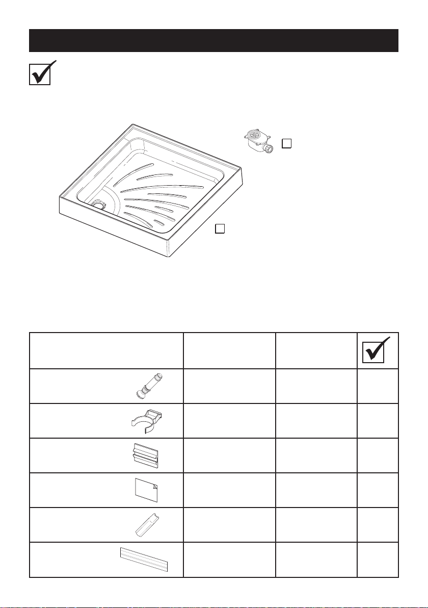
PACK CONTENTS
Tick the appropriate boxes to familiarise yourself with the part names and to
conrm that the parts are included.
Square or Rectangular Shower Tray
1 x 85 mm Waste
1 x Square or Rectangular Shower Tray
Square/Rectangular Riser Conversion Kit (if purchased)
Description
Quantity
Square
or 900 x 760 rectangle
Quantity
Rectangle
all other rectangles
Adjustable Legs 4 6
Clips 4 6
Locators 4 6
Sticky Pads 5 7
90° Corner 1 1
Panels 2 2
4
Page 5
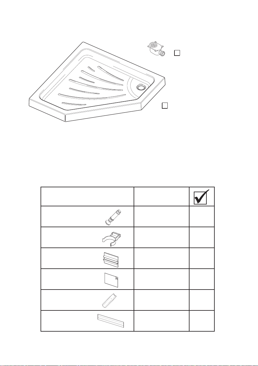
Pentangle Shower Tray
Pentangle Riser Conversion Kit (if purchased)
Description Quantity
1 x 85 mm Waste
1 x Pentangle Shower Tray
Adjustable Legs 5
Clips 5
Locators 5
Sticky Pads 6
135° Corner 2
Panels 3
5
Page 6
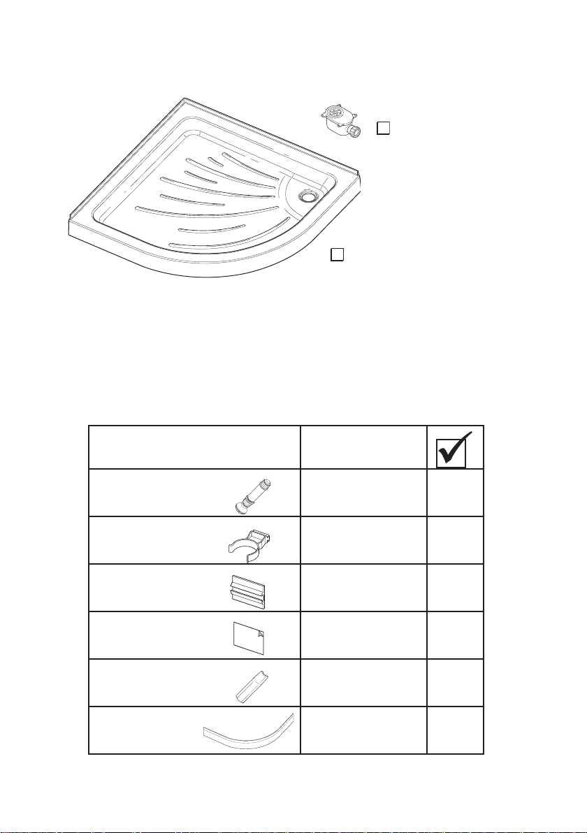
Quadrant Shower Tray
Description Quantity
1 x 85 mm Waste
1 x Quadrant Shower Tray
Adjustable Legs 4
Clips 4
Locators 4
Sticky Pads 5
90° Corner 1
Panels 1
6
Not
Used
Page 7
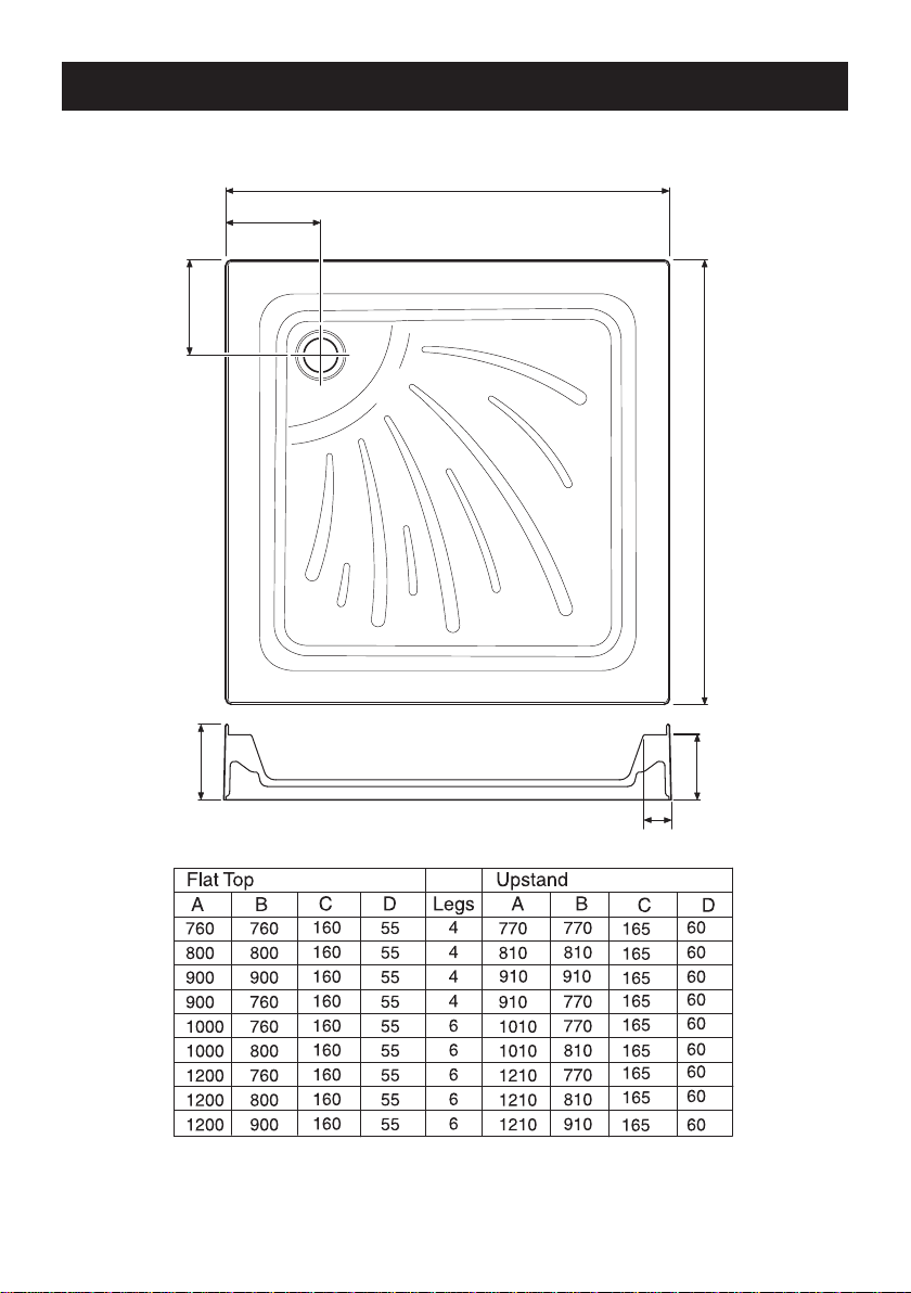
Square or Rectangular Shower Tray
90
B
A
C
C
112
D
DIMENSIONS
All Dimensions in mm
7
Page 8
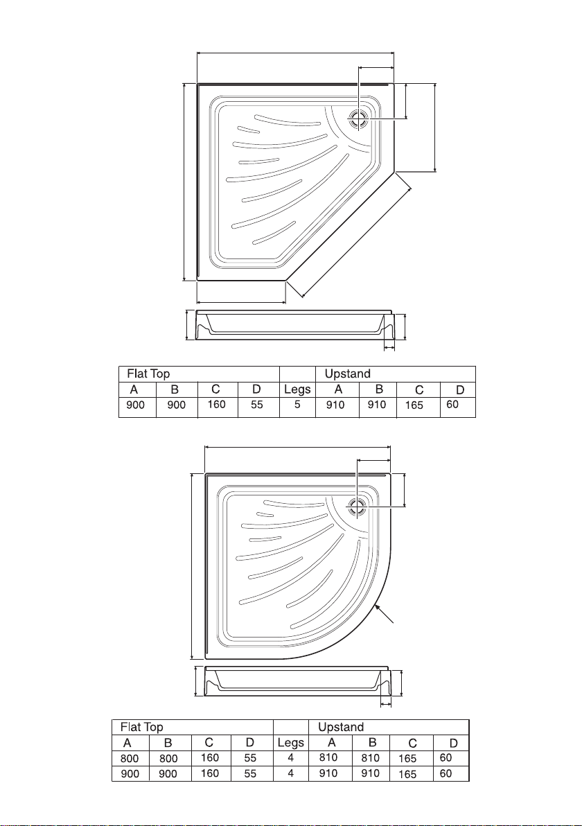
90
Radius 550
D
112
B
C
C
A
90
D
112
707
410
410
B
A
C
C
Pentangle Shower Tray
Quadrant Shower Tray
All Dimensions in mm
8
Page 9

INSTALLATION
Please read these instructions carefully before starting the installation
procedure.
Important Notes
1. It is recommended that the shower tray is installed before tiling. This will make
sure that the tray is rebated into the plaster behind where the tile face will be,
thus helping to achieve a watertight joint.
2. With a rebate or partial rebate the amount of adjustment on the enclosure could
be affected. Therefore make sure that the enclosure to be tted has sufcient
adjustment to mate with the shower tray.
3. A waste with an 85 mm diameter ange must be used with these shower trays
as supplied.
The rst step of the installation is to decide whether you need a non-riser or riser
installation for your tray. To nd out answer these simple questions.
1. If the oor is out of level by 1/4” (6 mm) or more across the
tray length the installation of a riser tray is recommended
2. Can a hole be made to t the waste into
the oor/timber/between the joists
YES NO
Follow Non‑Riser
Installation Procedure
Follow Riser Installation
Procedure and Purchase a
Riser Conversion Kit
9
Page 10

Non‑Riser Installation
1. Carefully remove all of the blue protective lm from the tray for inspection.
Caution! Additional protective coverings such as a dust sheet should then be
used to protect the tray from damage from falling objects.
2. Fit the 85 mm top access waste (supplied) to the tray before setting down being
careful not to overtighten. Make sure that the seal is in place. Additional beads
of silicone sealant must be used (refer to Figure 1).
Note! To tighten, remove the Shower Grid from the Flange and turn it upside
down. Locate it into the slots on the ange and tighten in a clockwise direction.
Remove and ret the Shower Grid to it’s original position.
Shower Grid
(invert to
tighten ange)
Bead of
Silicone Sealant
Flange
For Non-Riser
Installations coat the
underside of the tray with
silicone sealant, a tiling
cement or a weak mix of
sand and cement (5:1)
Figure 1
Install the Tray Waste
Seal
3. Position the tray up to the walls and rebate into the plaster as required, refer
to section: ‘Installation, Rebating the Shower Tray’. Remove the tray from
its position.
4. Make sure that the oor is clean, dry, rm and level. Coat the ribbed underside
of the tray with silicone sealant, a tiling cement or a weak mix of sand and
cement (5:1). Then press down into place ensuring the tray is positioned into
rebates.
Note! Where the tray comes into contact with the wall or plaster board surface,
apply a liberal amount of silicone sealant before installation. This will help secure
the tray in position and reduce any rubbing of the surfaces.
10
Page 11

5. Make sure that the tray is level.
Note! The bottom of the shower tray has a built in fall to allow for correct
drainage. Therefore check the edges of the tray with a spirit level (refer to
Figure 2).
Make sure that the
shower tray is level
Figure 2
Level the Shower Tray
Connect the waste pipe.
6.
7. Seal the joint between the shower tray and adjoining wall with silicone sealant
to provide a secondary seal.
The area is now ready for tiling.
8.
9. The 3 mm gap between the tiling and the shower tray must be lled with a
bead of silicone sealant, refer to section: ‘Installation, Rebating the Shower
Tray’.
11
Page 12

Riser Installation
1. Carefully remove all of the blue protective lm from the tray for inspection.
Attention should then be paid to effectively cover the tray to protect from
damage.
2. Spots on the adjustable leg mouldings are provided to help set equal heights.
Set the adjustable legs to the third spot from the bottom, this will give the initial
clearance for the waste supplied.
Note! Do not adjust the legs above the fourth spot as this will be too high to
accommodate the riser panel.
3. Fit the adjustable legs into the holes on the back of the tray.
Note! A soft faced mallet can be used to aid installation.
4. Temporarily t the waste outlet pipework and the trap to the tray. Adjust the
height of the feet to give the required clearance.
Note! The feet must be adjusted so that the shower tray does not rock.
5. Position the tray up to the walls and rebate the tray into the plaster (as required),
refer to section: ‘Installation, Rebating the Shower Tray’.
Note! Where the tray comes into contact with the wall or plaster board surface,
apply a liberal amount of silicone sealant before installation. This will help secure
the tray in position and reduce any rubbing of the surfaces.
6. Make sure that the tray is level.
Note! The bottom of the shower tray has a built in fall to allow for correct
drainage, therefore check the edges of the tray with a spirit level (refer to
Figure 2). If necessary adjust the height of the feet so that the tray is level in
all directions.
7. Once the tray is level - tighten the individual lock nuts on the leg sets and check
the tray is rm and secure.
8. Tighten the waste being careful not to overtighten. Make sure that the seal is in
place, additional beads of silicone sealant must be used (refer to Figure 1).
9. Connect the waste pipe.
10. Seal the joint between the shower tray and adjoining wall with silicone sealant
to provide a secondary seal.
11. The area is now ready for tiling.
12. The 3 mm gap between the tiling and the shower tray must be lled with a
bead of silicone sealant, refer to section: ‘Installation, Rebating the Shower
Tray’.
12
Page 13

Rebating the Shower Tray
The gures below provide an indication of the type of typical recommended
installation methods. It does not provide a fully detailed description for ALL installation
methods / procedures.
To aid installation, optional accessories are available, refer to section
‘Accessories’.
Plasterboard
9.5 mm Thick
3 mm
Gap
Plasterboard
9.5 mm Thick
3 mm
Gap
Plasterboard
9.5 mm Thick
Grout
2 mm Thick
Tile
5 mm Thick
Clear Area
Silicone Sealant
A
Grout
2 mm Thick
Tile
5 mm Thick
Clear Area
Silicone Sealant
C
Grout
2 mm Thick
Tile
5 mm Thick
16.5 mm
16.5 mm
16.5 mm
Plasterboard
9.5 mm Thick
3 mm
Gap
Plasterboard
9.5 mm Thick
3 mm
Gap
Plasterboard
9.5 mm Thick
Grout
2 mm Thick
Tile
5 mm Thick
Clear Area
Silicone Sealant
B
Grout
2 mm Thick
Tile
5 mm Thick
Clear Area
Silicone Sealant
D
Grout
2 mm Thick
Tile
5 mm Thick
16.5 mm
16.5 mm
16.5 mm
3 mm
Gap
Clear Area
Silicone Sealant
E
THIS SIDE SHOWN
WITH SOLID WALL
Note:- The amount of rebate affects the enclosure size.
3 mm
Gap
Figure 3
Rebating the Shower Tray
13
Clear Area
Silicone Sealant
F
THIS SIDE SHOWN
WITH STUD PARTITION
Page 14

BASIC PANEL INSTALLATION
Square/Rectangle
Cut the panel to length.
1.
Note! When cutting to length, make sure that you take into account the amount
of panel that goes into the corner connector.
Note! The panel can be cut or shaped to suit the wall prole e.g. skirting
board.
2. Remove the backing from one side of each of the pads and stick the pads to
back of locators.
3. Slide the locators onto the clips (refer to Figure 4).
Pad
Locator
Clip
Figure 4
Assemble the Panel Fixings
4. Slide the clips onto the legs until the bottom edge of the pad is 55 mm from the
oor. Where two clips are tted on one leg, one of the clips can be inverted to
allow both pads to be located at the same height.
Note! Make sure that they are parallel to the tray edge (refer to Figure 5).
Figure 5
Install the Locators and Clips
14
Locator and Clip
(with adhesive
pad attached)
55 mm
Make sure that the
top edge of the clip is
parallel to the tray
Page 15

5. Offer up the panel to the tray with the horizontal grooves nearest the oor and
make sure that the panel is the correct length.
Note! If extra panel stability is required, secure wooden blocks or batons to the
oor along the rear edge of the panel as shown.
6. Remove the backing paper from the sticky pads and remove the protective lm
from the panel.
7. Starting at the wall end. Offer the panel up to the locator and press rmly.
Continue along the panel making sure that it sticks correctly (refer to Figure
6).
8. Fit the corner to the other panel.
9. Fit the corner onto the xed panel and continue along pressing rmly.
10. Seal the top edge of the panel to the tray wall using a line of silicone sealant.
Wooden
Block or
Baton
Panel
Panel
Corner
Figure 6
Install the Panels
15
Page 16

Pentangle
1. Cut the panel to length.
Note! When cutting to length, make sure that you take into account the amount
of panel that goes into the corner connector.
Note! The panel can be cut or shaped to suit the wall prole e.g. skirting
board.
2. Remove the backing from one side of each of the pads and stick the pads to
back of locators.
3. Slide the locators onto the clips (refer to Figure 7).
Pad
Locator
Clip
Figure 7
Assemble the Panel Fixings
4. Slide the clips onto the legs until the bottom edge of the pad is 55 mm from the
oor.
Note! Make sure that they are parallel to the tray edge (refer to Figure 8).
55 mm
Figure 8
Install the Locators and Clips
16
Locator and Clip
(with adhesive
pad attached)
Make sure that the
top edge of the clip
is parallel to the
tray.
Page 17

5. Offer up the panel to the tray with the horizontal grooves nearest the oor and
make sure that the panel is the correct length.
Note! If extra panel stability is required, secure wooden blocks or batons to the
oor along the rear edge of the panel as shown.
6. Remove the backing paper from the sticky pads and remove the protective lm
from the panel.
7. Starting at the wall end. Offer the panel up to the locator and press rmly (refer
to Figure 9).
8. Fit the corner onto one end of the larger panel (710 mm) so that it ts onto the
tted panel.
9. Locate onto the tted panel (410 mm) and rmly press onto the pads.
10. Fit the second corner onto one end of the panel (410 mm) so that it ts onto
the tted panel (710 mm).
11. Press the panel rmly onto the locators.
12. Seal the top edge of the panel to the tray wall using a line of silicone sealant.
Wooden
Block or
Baton
Corner
Figure 9
Install the Panels
17
Panel
Corner
Page 18

Quadrant
1. Cut the panel to length.
Note! Cut each end equally to maintain the correct t of the curved panel.
The panel can be cut or shaped to suit the wall prole e.g. skirting board.
2. Remove the backing from one side of each of the pads and stick the pads to
back of locators.
3. Slide the locators onto the clips (refer to Figure 10).
Pad
Locator
Clip
Figure 10
Assemble the Panel Fixings
4. Slide the clips onto the legs until the bottom edge of the pad is 55 mm from the
oor. Make sure that they are parallel to the oor (refer to Figure 11).
Make sure that
55 mm
the top edge of
the clip is parallel
to the tray.
Figure 11
Install the Locators and Clips
18
Locator and Clip
(with adhesive
pad attached)
Page 19

5. Offer up the panel to the tray and make sure that the panel is the correct
length.
Note! If extra panel stability is required, secure wooden blocks or batons to the
oor along the rear edge of the panel as shown.
6. Remove the backing paper from the sticky pads and remove the protective lm
from the panel.
7. Put the panel in position and press rmly. Continue along the panel making
sure that it sticks correctly (refer to Figure 12).
8. Seal the top edge of the panel to the tray wall using a line of silicone sealant.
Wooden
Block or
Baton
Panel
Figure 12
Install the Panels
19
Page 20

MAINTENANCE
General
Providing the shower tray has been correctly installed in accordance with the
instructions contained in this guide, difculties should not arise. If any maintenance
is required then it must be carried out by a competent tradesperson for whom the
maintenance instructions are provided.
Cleaning
It is advised that the shower tray is cleaned immediately after use, to remove any
insoluble products. Hot soapy water should be used and then the tray should be
wiped. Cleaners of gritty or abrasive nature should never be used.
The acrylic ABS surface of this shower tray has good resistance properties to acids
but should not come into contact with alkalis or organic solvents, such as caustic
soda, dry cleaning agents and paint strippers.
20
Page 21

ACCESSORIES
Genuine Mira accessories can be purchased direct from Customers Services (our
contact details can be found on the back cover of this guide) or from approved
stockists or merchants.
Apply Silicone
Sealant
Shower Tray
Offset Leg adaptor
Adjustable Leg
(with locking Nut removed)
Offset Leg Adaptor Fittings Kit (2 off) ‘Patent
Pending’
1570.557 WH (white)
The Offset Leg Adaptor allows the Adjustable
Legs to be installed offset to the tray, thus
allowing installation of pipework behind the
Adjustable Legs (refer to illustration).
Important! Unscrew and remove the Locking
Nut when using the Offset Leg Adaptor.
Shower Seat
White - 2.1536.128
White/Chrome - 2.1536.129
For use in or out of the showering area. Note!
Must be installed onto a solid wall.
Shower seat folds up when not in use
Upstand Tiling Strip (3 off, 1250 mm long)
1570.558 WH (white)
Eliminates the need to rebate the shower tray
into solid or stud walls.
Wall Mounted Soap Dish
White - 1.1540.278
Chrome - 1.1540.279
Wall mounted for use anywhere in, or outside
the showering area.
21
Page 22

SPARE PARTS
1570.002 WH
1570.002 SC (soft cream)
1570.002 PG (pergamon)
1570.003 WH (white) Connector (135 Degrees)
1570.003 SC (soft cream)
1570.003 PG (pergamon)
1570.004 WH (white) Quadrant Panel
1570.004 SC (soft cream)
1570.004 PG (pergamon)
1570.005 WH (white) 1200 mm Panel
1570.005 SC (soft cream)
1570.005 PG (pergamon)
1570.589 WH (white) End Piece
1570.589 SC (soft cream)
1570.589 PG (pergamon)
(white) Connector (90 Degrees)
(for use with Square, Rectangle and Pentangle Trays)
1570.280 Mira Flight Riser Fittings Pack
Comprising of: 1 Leg
1 Clip
1 Locator
2 Sticky Pads
1570.296 6 Leg Pack
22
Page 23

NOTES
23
Page 24

CUSTOMER SERVICE
Guarantee
Your product has the benefi t of our manufacturer’s 10
year guarantee which starts from the date of purchase.
To activate this guarantee, please return your completed
registration card, visit our w ebsite or free phone
0800 0731248 within 30 days of purchase (UK only).
Within the guarantee period we will resolve defects in
materials or workmanship by either repairing the product,
providing new goods and parts to you in replacement
or refunding (up to but not in excess of) the original
purchase price, as we may choose.
This guarantee is in addition to your statutory rights
and is subject to the following conditions:
● The guarantee applies solely to the original installation
under normal use and to the original purchaser only.
The product must be installed and maintained in
accordance with the instructions given in this user
guide. The product must be inspected and issues
reported before installation.
● Servicing must only be undertaken by us or our
appointed representative. Note! if a service visit
is required the product must be fully installed and
connected to services.
● Repair under this guarantee does not extend the original
expiry date. The guarantee on any replacement
parts or product ends at the original expiry date.
● For trims or consumable items we reserve
the right to supply replacement parts only.
The guarantee does not cover:
● Call out charges for damge or defects c aused
by incorrect installation, frost damage, mildew,
limescale, corrosion, lack of maintenance, improper
use, inappropriate cleaning (please refer to our Care
and Maintenance Instructions) or where no fault has
been found with the product.
● Compensation for loss of use of the product or
consequential loss of any kind.
● Damage or defects caused if the product is repaired
or modifi ed by persons not authorised by us or our
appointed representative.
● Wear and tear.
● Accidental or wilful damage.
● Products purchased ex-showroom display.
● Costs of removal of the product following installation
and/or reinstallation of any replacement product (or
part) including without limitation, tiling costs.
IMPORTANT! Trays must be inspected for defects
and/or distortion prior to installtion. This Guarantee
does not cover the costs of removal and/or
reinstallation where a defect would have been
discovered by inspection prior to installation.
What to do if something goes wrong
If your product does not function correctly when you fi rst
use it, contact your installer to check that it is installed
in accordance with the instructions in this manual. If this
does not resolve the issue, contact us for help and advice.
Mira is a registered trade mark of
Kohler Mira Limited.
The company reserves the right to alter
product specifi cations without notice.
1056862-W2-E © Kohler Mira Limited, September 2012
24
Helpdesk Service - Contact our Customer
Services Team for product advice, to purchase
spare parts or accessories or to set up service
visit. We will need you to have your model name
or number and date of purchase.
Mira Showers Website (www.mirashowers.
co.uk)
Visit our website to register your guarantee,
download user guides, diagnose faults,
purchase our full range of accessories and
popular spares, or request a service visit.
Spares and Accessories - We hold the largest
stocks of genuine Mira spares and accessories.
Contact us for a price or visit our website to
purchase items from our accessory range and
popular spares
Service/Repairs - No one knows our products
better than our nationwide team of Service
Technicians. We can carry out service or repair
work to your product both during and after the
guarantee period. Ask about our fi xed price
service repairs.
.
To Contact Us: UK
0844 571 5000
Fax: 01 242 282595
E-mail: Visit www.mirashowers.co.uk/
contactus
Mira Customer Services Dept, Cromwell
Road, Cheltenham, Gloucestershire, GL52
5EP
To Contact Us: Eire Only
01 459 1344
Fax: Dublin 01 459 2329
E-mail: sales@modernplant.ie
Modern Plant Ltd (Dublin),
Otter House, Naas Road, Clondalkin, Dublin
22
FM 14648
Page 25

Pdf Supplied By http://www.plumbworld.co.uk/
 Loading...