

Page 1
1
1265606-W2-A
Installation & User Guide
These instructions must be left with the user
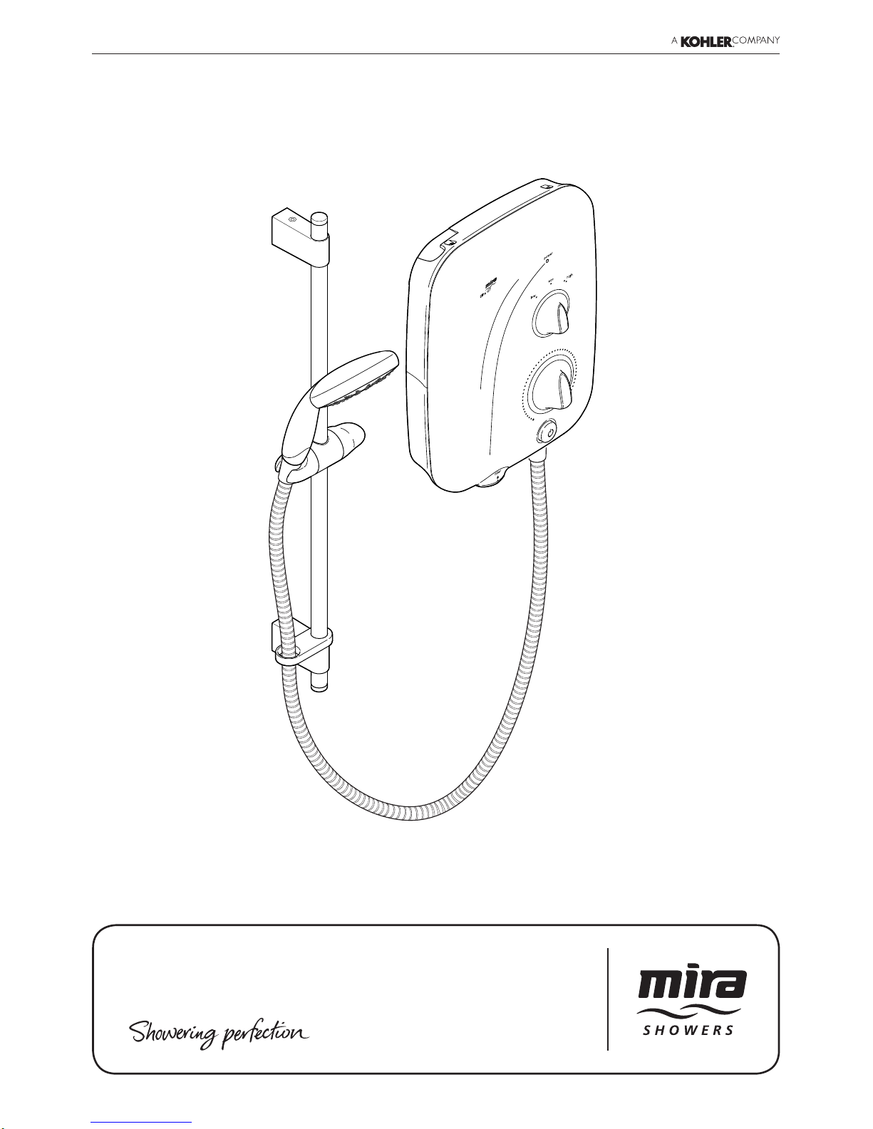
Mira Elite QT 9.8kW / 10.8kW
Page 2

2
1265606-W2-A
Important Safety Information
WARNING! This shower can deliver scalding temperatures. For
continued safe operation, follow all instructions, warnings and
cautions contained in this guide and on or inside the shower unit.
Failure to follow the instructions provided with the shower will
invalidate the guarantee.
PLEASE OBSERVE THE FOLLOWING TO REDUCE THE RISK OF
FIRE, ELECTRIC SHOCK OR INJURY:
INSTALLING THE SHOWER
1. Installation of the shower must be carried out in accordance with
these instructions by qualied, competent personnel. Read all
instructions before installing the shower.
2. Isolate the electrical and water supplies before commencing
installation. The electricity must be isolated at the consumer unit
and the appropriate circuit fuse removed, if applicable. Mains
connections are exposed when the shower cover is removed.
3. DO NOT install the shower in areas with high humidity and
temperature (i.e. steam rooms and saunas).
4. DO NOT install the shower where it may be exposed to freezing
conditions. Ensure that any pipework that could become frozen
is properly insulated.
5. DO NOT connect the outlet of the shower to any tap, control valve,
trigger handset or showerhead other than those specied for use
with this shower. Only Kohler Mira recommended accessories
must be used.
6. DO NOT perform any unspecied modications, drill or cut holes
in the shower or ttings other than instructed by this guide. When
servicing only use genuine Kohler Mira replacement parts.
7. If the shower is dismantled during installation or servicing then,
upon completion, an inspection must be made to ensure all
electrical connections are tight and that there are no leaks.
USING THE SHOWER
8. The shower must be operated and maintained in accordance with
Page 3

3
1265606-W2-A
the requirements of this guide. Make sure you fully understand
how to operate the shower before use, read all instructions and
retain this guide for future reference.
9. DO NOT switch the shower on if there is a possibility that the
water in the shower unit or ttings is frozen.
10. DO NOT switch the shower on if water leaks from the shower
unit. Isolate the electrical supply to the shower immediately.
11. DO NOT switch the shower on if the case appears to be damaged
or incorrectly tted. Isolate the electrical supply to the shower
immediately.
12. The shower can be used by children aged from 8 years and above
and persons with reduced physical, sensory or mental capabilities
or lack of experience and knowledge if they have been given
supervision or instruction concerning use of the appliance in a
safe way and understand the hazards involved. Children must
not be allowed to play with the shower.
13. DO NOT allow children to clean or perform any user maintenance
to the shower unit without supervision.
14. Always check the water temperature is safe before entering the
shower.
15. DO NOT increase the power setting or adjust the temperature
control rapidly while using the shower.
16. Use caution when altering the water temperature, always check
the temperature before continuing to shower.
17. DO NOT switch the shower off and back on while standing in
the water ow.
18. DO NOT run the shower with the lter removed.
19. Switch the shower off at the electrical isolating switch when not
in use. This is recommended with all electrical appliances.
20. DO NOT connect the outlet of the shower to any tap, control valve,
trigger handset or showerhead other than those specied for use
with this shower. Only Kohler Mira recommended accessories
must be used.
21. The showerhead must be descaled regularly. Any blockage of the
showerhead or hose can cause damage to the shower.
Page 4
4
1265606-W2-A
Introduction
Guarantee
Recommended Usage
This product has been designed for domestic use only, Mira Showers guarantee this product
against any defect in materials or workmanship for a period of two years from the date of
purchase (shower ttings for one year).
For terms and conditions, refer to the back cover of this guide.
Recommended Usage
Domestic
Light Commercial
Heavy Commercial
Healthcare
Thank you for choosing a Mira shower. To enjoy the full potential of your new shower,
please take time to read this guide thoroughly, and keep it handy for future reference.
Products manufactured by Kohler Mira Ltd are designed to be safe, provided that they are
installed, used and maintained in good working order, in accordance with our instructions
and recommendations.
Follow all warnings, cautions and instructions contained in this guide, and on, or inside
the shower. This guide is also available in digital format from our website or by contacting
customer services.
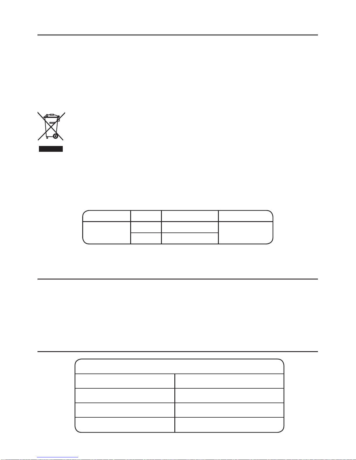
Electrical and electronic devices contain a range of materials that can be separated
for recycling and used in new products.
This product should not be disposed of with your general household waste. When this product
has reached the end of its serviceable life please take it to a recognised WEEE (Waste Electrical
and Electronic Equipment) collection facility such as your local civic amenity site for recycling.
Your local authority or retailer will be able to advise you of your nearest recycling facility.
Mira Electric Showers covered by this guide:
Product kW Model Number Colour
Mira Elite QT
9.8 J08I
White / Chrome
10.8 J08J
Page 5
5
1265606-W2-A
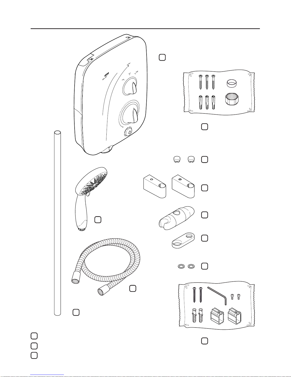
Pack Contents
1 x Shower Unit
2 x Caps
1 x Component Pack
(shower fittings)
2 x Slide Bar Supports
1 x Slide Bar
1 x Hose
1 x Clamp Bracket
1 x Showerhead
2 x Washers
1 x Hose Retaining Ring
1 x Component Pack
(shower unit)
1 x Installation & User Guide
1 x Installation Template (remove from packaging)
1 x Guarantee Card
Page 6
6
1265606-W2-A
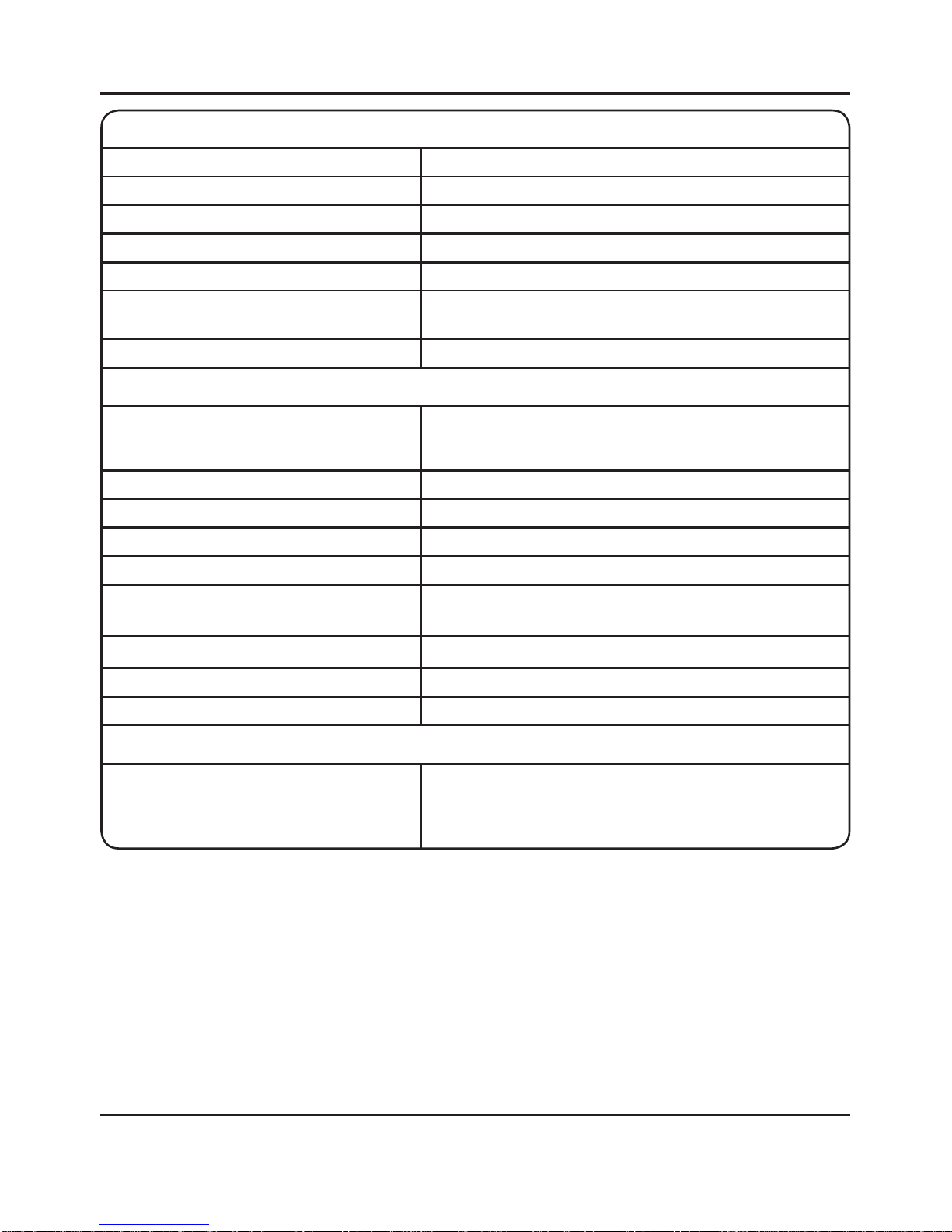
Specications
The Mira Elite QT complies with the following European directives:
2006/95/EC Low Voltage Directive, 2004/108/EC EMC Directive, 2011/65/EU RoHS Directive.
The Mira Elite QT is a high power appliance and is subject to conditional connection. If the
main electrical supply fuse is rated less than 80 Amps, the local electricity supply company
must be contacted to conrm if the electrical supply is adequate.
The Mira Elite QT complies with the requirements of the UK’s water regulations.
Design Registration & Patents
Patents: GB 2 289 323, 2 341 667, 2 359 339, 2 427 460, 2 432 201
Ireland: 80655, 82835, 83692
Plumbing
Maximum Static Pressure 100 kPa (1 bar)
Minimum Static Pressure 0.8 kPa (0.008 bar)
Minimum Inlet Temperature 2°C
Maximum Inlet Temperature 30°C
Maximum Water Hardness 200 ppm CaCO
3
Inlet
15 mm compression. Adjustable for top, bottom or rear
entry pipework.
Outlet 1/2" BSP Male to exible hose
Electrical
Power Supply
230 - 240 V, 50 Hz
9.8 kW model (230 V = 9.0 kW, 240 V = 9.8 kW)
10.8 kW model (230 V = 9.9 kW, 240 V = 10.8 kW)
Duty Cycle Continuously rated.
Maximum Supply Cable Size 16 mm²
Recommended RCD Rating 30 mA tripping current
Recommended Isolator Switch Double-pole with 3 mm contact separation, 45 A
Recommended MCB Rating 9.8 kW model = 40 A
10.8 kW model = 45 A
Ingress Protection Rating IP X4 - Suitable for installation in Zone 1
Minimum Ambient Temperature 2°C
Maximum Ambient Temperature 30°C
Dimensions (shower unit)
Height 363 mm
Width 270 mm
Depth 110 mm
Page 7
7
1265606-W2-A
Installation
Plumbing
1. The plumbing installation must comply with all national or local water regulations and
all relevant building regulations, or any particular regulation or practice specied by
the local water supply company.
2. The shower is designed to operate with a gravity fed water supply providing a pressure
from 0.8 kPa* (0.008 bar / 80 millimetres head) to 100 kPa (1 bar / 10 metres head,
the vertical distance from the base of the cold water cistern to the top of the shower
unit). The shower must have its own separate supply from the cistern.
DO NOT FIT THE SHOWER TO A MAINS WATER SUPPLY OR WHERE THE
MAXIMUM SPECIFIED PRESSURE MAY BE EXCEEDED!
Failure to comply with these restrictions may result in product damage not covered
by the guarantee.
* Note! In practice the minimum head required will increase with pipe length. See
“Pipework” for further guidance which includes a calculation table to make sure that
adequate head is available for any given installation.
3. DO NOT install the product in a position or location that will
limit access for servicing.
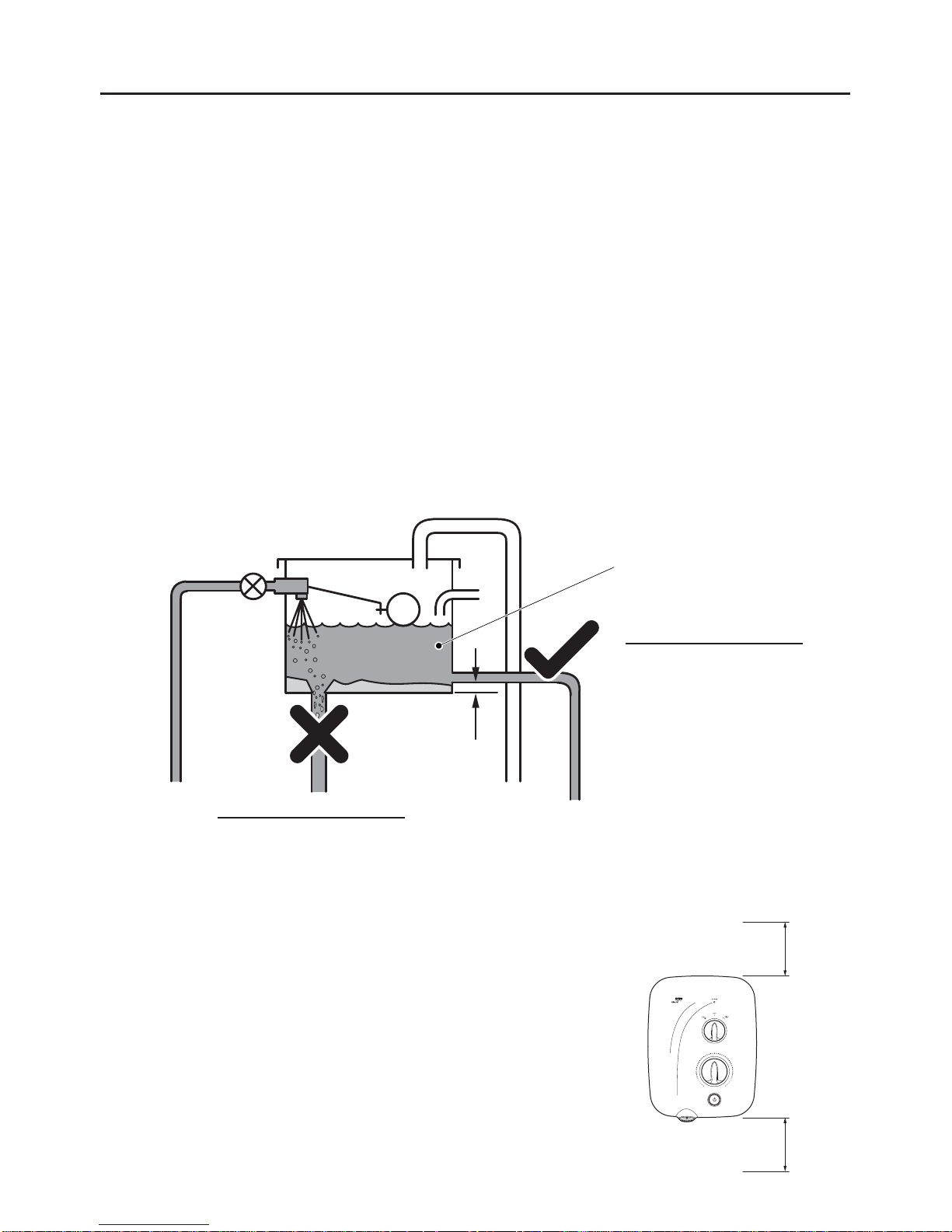
4. A suitable position for the shower will have a minimum clear
distance of 200 mm above and below the shower unit to
allow for cover removal and retting.
5. The position of the shower and shower ttings must provide
a minimum air gap of 25 mm between the showerhead
and the spill over level of any bath, shower tray or basin.
There must be a minimum distance of 30 mm between the
200 mm
200 mm
Incorrect Cistern Take Off
Debris from the bottom of the
cistern and air generated when
the cistern rells will enter the
shower supply.
Correct Cistern Take Off
Positioned away from the ball
valve, with a 25 mm distance
from the base of the cistern.
This connection will prevent
air and debris entering the
shower supply.
To shower
unit only.
25 mm
25 Gallon/113 Ltr Cistern
Page 8

8
1265606-W2-A
showerhead and the spill over lever of any toilet, bidet or other appliance with a Fluid
Category 5 backow risk.
6. The shower is suitable for installation within the shower area. The shower is tted with
an internal pressure relief valve and must be installed over a water catchment area.
7. Position the shower where the controls area at a convenient height for the user.
Position the showerhead so that the water sprays in line with the bath or across the
opening of a shower cubicle. The showerhead must not spray directly onto the shower
unit during normal use. The installation must not cause the shower hose to be kinked
during normal use.
8. The shower must be tted to a waterproof, at and even wall surface. The 3 screws
(No. 8 x 1¼”) and wall plugs supplied are suitable for most solid wall installations. Alternative
xing screws for panel structures are not supplied. Use all 3 xing points to secure the
shower unit, be sure to use xings appropriate for the chosen wall structure.
DO NOT t the shower to the wall and tile up to the case or seal the gap between the
shower and the wall surface with sealant.
9. The shower is intended to be permanently connected to a gravity fed water supply
using the inlet connection supplied as part of the shower unit.
DO NOT use any other type of tting.
10. Use a minimum of 15 mm diameter supply pipework. For long pipe runs, this should
be increased to 22 mm (see “Pipework” for guidance and calculation table). When
using exible plastic pipe it is essential that the pipe is kept at to minimise air build
up in the system.
11. A full bore/non restrictive servicing valve must be tted in a readily accessible position
adjacent to the shower to facilitate maintenance of the shower.
Note! There will be occasions
when the hose retaining ring
will not provide a suitable
solution for Fluid Category 3
installations. In these instances
an outlet double checkvalve
must be tted, this will increase
the required supply pressure
typically by 10 kPa (0.1 bar).
Double checkvalves tted
in the inlet supply to the
appliance cause a pressure
build up, which affects the
maximum static inlet pressure
for the appliance and must not
be tted. For Fluid Category
5, double checkvalves are not
suitable.
Zone of
Backflow
Risk
30 mm
Minimum
Toilet or Bidet
FC5
Hand Basin
FC3
Bath or Shower
Tray FC3
Shower
Unit
25 mm
Minimum
25 mm Minimum
Page 9
9
1265606-W2-A
DO NOT use a valve with a loose washer plate (jumper) as this can lead to a build
up of static pressure.
12. The shower is not designed to be plumbed directly from the rear. For rear-entry
supply, add an elbow to the supply pipe and connect as a rising or falling supply. We
recommend a falling supply to prevent air lock in the pipework.
13. If pipework and/or electrical cables enter the shower from the rear through a hole in
the wall, provision must be made to prevent water ingress back into the wall structure.
14. DO NOT apply excessive force to plumbing connections; always provide mechanical
support when making plumbing connections. Any soldered joints should be made
before connecting the shower.
15. A water treatment device should be installed where the water hardness may exceed
200 ppm. Malfunctions caused by excessive limescale formation are not covered by
the guarantee.
16. DO NOT perform the electrical installation until the plumbing has been completed and
checked for leaks.
17. The water supplies to this product should be isolated if the product is not to be used
for a long period of time. If the product or pipework is at risk of freezing during this
period they should also be drained of water.
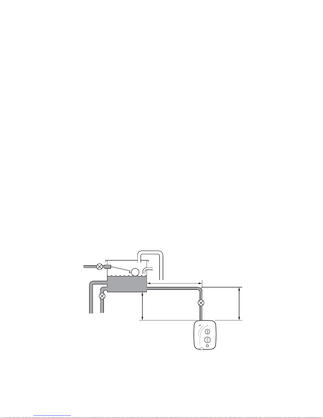
Pipework
Long pipe runs and excessive use of 90° elbow ttings will signicantly reduce the available
head to supply the shower unit. The pipework table provided should be used to ensure that
an adequate pressure is available for any given application.
Pipework Schematic Diagram
A
B
X
Use the following table to calculate the dimension (x) to give a minimum effective head of
80 mm required to produce a satisfactory shower in all conditions.
Page 10

10
1265606-W2-A
The example below is based on the “Pipework Schematic Diagram” with 15 mm pipework,
A = 1.5 m, B = 0.75 m.
(A)
(A)
1.5 + (B)
+ (B)
Number of Elbows
Number of Elbows
0.75 2.25
1
120
20
55
15
x
x
x
x
=
=
Electrical
1. The electrical installation must comply with BS 7671 (commonly referred to as the IEE
Wiring Regulations) and all relevant building regulations, or any particular regulation
or practice specied by the local electricity supply company.
2. Ensure that all circuit protection devices, switches and cabling are adequate for the
rated current of the shower and that the rating of the electricity supply company fuse
and the consumer unit are adequate for the additional demand.
3. The shower must be earthed. Ensure that any supplementary bonding complies with
the relevant regulations.
4. The shower is intended to be permanently connected to the xed electrical wiring of
the mains system. A separate supply must be provided from the consumer unit to the
shower.
5. The shower must be provided with means for local disconnection that is incorporated
into the xed wiring in accordance with the relevant local wiring regulations. This must
be a double pole switch, which has at least 3 mm contact separation in each pole.
The switch can be a pull-cord type mounted to the ceiling within the shower room or
a rocker type switch mounted to the wall in the applicable zone area.
6. For new installations a 30 mA Residual Current Device (RCD) must be incorporated into
the electrical supply to the shower in accordance with the current wiring regulations.
When replacing an existing electric shower we recommend that a 30 mA RCD is
incorporated in accordance with current wiring regulations if not already provided.
Size Quantity Head Loss (mm)
15 mm Pipe 270
22 mm Pipe
15 mm Elbow
55
22 mm Elbow
Minimum Effective Head 80
(X) mm 405
Page 11

11
1265606-W2-A
Electrical Schematic Diagram
Shower Unit Wiring Diagram
7. Check all electrical connections are tight, to prevent overheating, before switching on
the electrical supply.
DO NOT apply excessive force to the terminal block.
8. DO NOT supply any other electrical equipment including extractor fans or pumps via
the shower unit.
9. DO NOT switch on the electrical supply until the plumbing has been completed and
checked for leaks.
PUMP
TERMINAL
BLOCK
HEATER
TANK
POWER
NEON
BLUE
BLUE
GREY
RED
RED
GREEN
GREEN
GREY
BROWN
BROWN
BROWN
BROWN
BROWN BLUE
BLUE
MICRO
SWITCH (L)
MICRO
SWITCH (R)
START / STOP
SWITCH
INLET
CONNECTOR
SOLENOID
Consumer Unit
Double Pole
Isolating Switch
Shower
Unit
Page 12

12
1265606-W2-A
1
2
Warning, isolate the electrical and water supplies before installing the shower!
3
Remove the cover screws, cover and
service tunnel. Keep the screws for
further use.
Decide on a suitable position for the shower unit and ttings.
See “Installation - Plumbing” for further details.
Hold the template against the wall and
mark the positions of the 3 xing holes.
Installation of the Shower Unit
Page 13

13
1265606-W2-A
4
5
Drill the xing holes.
DO NOT drill through the shower unit into the wall.
DO NOT drill into buried cables or pipes.
Feed the water pipe and electrical
cable to the inlet of the shower unit.
For rear inlet, use an elbow tting. We
recommend a falling supply to prevent
air lock in the pipework.
6
For a falling water supply pipe, carefully
remove the thinned section of the rear
case using an appropriate cutting tool.
Thinned
Section
Rear Case
Page 14

14
1265606-W2-A
7
8 9
Fix the shower unit to the wall, 3 x No. 8 x
1¼” screws and wall plugs are supplied.
See “Installation - Plumbing” for
further details.
Turn the water supply on and check
the shower unit for leaks.
Connect the water pipe to the shower
unit.
DO NOT use jointing paste.
DO NOT overtighten the tting.
DO NOT trap the green wire.
6
Thoroughly ush the water supply
pipe. Rotate the inlet connector to suit
the direction of the water supply.
Page 15

15
1265606-W2-A
Turn the water supply back off. Feed
the electrical cable into the shower
unit. Strip the insulation and t an earth
sleeve (not supplied). Secure the wires
rmly into the terminal block.
Install the shower ttings provided with
this shower, see “Installation of the
Shower Fittings”.
The shower must be commissioned
before use, see “Commissioning” for
full instructions.
Ret the service tunnel. Align the
controls with the spindles and ret the
cover. Secure with screws supplied.
DO NOT trap any wires.
DO NOT use alternative screws to
secure the cover. This can cause
internal damage to the shower unit.
(Neutral) = Blue Wire
(Live) = Brown Wire
(Protective Earth) =
Green / Yellow
Sleeved Wire
N
L
11
1312
10
Page 16

16
1265606-W2-A
Installation of the Shower Fittings
1
3
2
Mark and drill the xing points for
the wall screws. New installations
at a distance of 600 mm. Retrot
installations up to a maximum distance
of 635 mm.
Assemble the clamp bracket, hose retaining ring, slide bar supports and caps to
the slide bar.
Fix the brackets to the wall, 2 x No. 8 x
45 mm screws and wall plugs are
supplied. Use appropriate screws for the
wall structure and use a spirit level to
align the brackets vertically.
Cap
Cap
Slide Bar
Support
Slide Bar
Support
Clamp
Bracket
Hose
Retaining
Ring
New Installation
600 mm
Retrot Installation
635 mm Max.
Page 17

17
1265606-W2-A
4
6
5
7
Fit the slide bar supports over the
mounting brackets and adjust the slide
bar vertically. The slide bar should
extend equally at both ends.
Tighten the two slide bar clamping
screws no more than half a turn to
secure the slide bar supports to the
slide bar.
Caution! Overtightening these screws
will cause damage.
Remove the assembly, without moving
the supports on the slide bar.
Fix the slide bar at both ends with the
M4 screws supplied.
Page 18

18
1265606-W2-A
8
Feed the hose through the retaining ring and screw to both the showerhead
and shower unit. Use the washers supplied to seal the connections. Place the
showerhead assembly into the clamp bracket assembly and check the operation.
Turn the water supply back on.
Switch electrical supply on.Turn power control to low.
Turn temperature control to full cold.
Commissioning
1 2
Follow this procedure to check the function and performance before using the shower for the
rst time. Make sure that all users are familiar with the operation of the shower. This
guide is the property of the homeowner.
Showerhead
Assembly
Clamp Bracket
Assembly
Page 19

19
1265606-W2-A
Start shower running, water is cold and
at maximum ow.
Turn power control to eco. Water
temperature rises, but stays cool.
Turn power control to high. Water
temperature rises further.
Stop shower and switch electrical
supply off.
Turn temperature control to mid-
temperature. Water remains cold, but
ow is reduced.
Turn shower off.
Remove lter from shower unit.
Push rod up until water ows freely.
Ret lter, turn until locked.
AIR IN SYSTEM ?
Turn temperature control to test water
temperature change. Water ow
adjusts automatically as you adjust the
temperature.
Residual water may drain for a few
minutes.
3
6
8
10
7
9
5
4
Page 20

20
1265606-W2-A
Operation
Please read “Important Safety Information” before using the shower for the rst time.
Switch electrical supply on and start
shower.
Stop shower and switch electrical
supply off.
Check water temperature before
entering shower. Spray pattern can be
adjusted while showering.
Allow a few seconds for any temperature
adjustment to take effect.
Allow temperature to stabilise before
making a new adjustment.
Set power control to low / eco / high.
Adjust temperature control until desired
showering temperature is reached.
Residual water may drain for a few
minutes.
1
5
43
2
6
Page 21

21
1265606-W2-A
Please note when altering the shower temperature...
CAUTION! Altering the temperature control rapidly can cause the water temperature to
become briey hotter or colder than required. For best results, adjust the temperature control
a small amount and allow the temperature to stabilise. Continue to adjust until a comfortable
showering temperature is reached.
DO NOT increase the power setting while standing in the water ow. Avoid changing the
power setting when the shower is in use, this can cause a large increase or decrease in
water temperature.
DO NOT switch the shower off and back on while standing in the water ow. Cycling the
shower off/on may result in unstable water temperatures. Always ensure the temperature
has stabilised before re-using the shower.
The shower has a high performance pump installed, which has been acoustically designed for
quieter performance, but will produce some noise during operation. Pump tone may change
when altering temperature position.
For a cold shower select low.
For a summer warm shower select eco / high.
For a winter warm shower select high.
Adjust the power and temperature controls as required.
Flow rate will reduce when temperature control is increased.
COLD
HOT
Effect of Seasonal Changes
The temperature of the mains water feed to the cistern is not constant throughout the year, i.e.
cooler during winter, warmer during summer. To maintain the desired showering temperature,
adjust the power and temperature controls accordingly. The shower ow rate will adjust
automatically.
Page 22

22
1265606-W2-A
Cleaning / Replacing Filter
The lter can be safely removed from the lower left of the shower unit. Isolate the electrical
supply to the shower unit before removing the lter. The water supply will shut off automatically
as the lter is removed, however we recommend isolating the water supply to the shower unit
to aid with retting the lter.
Insert a suitable coin or an 8 mm hexagonal
key into the cap and turn to the left.
Rinse the lter in clean warm water removing
any dirt or debris. Replace if the lter mesh
is damaged. Make sure the lter is correctly
retted to the locked position.
21
User Maintenance
WARNING! PLEASE OBSERVE THE FOLLOWING TO REDUCE
THE RISK OF FIRE, ELECTRIC SHOCK, INJURY OR PRODUCT
DAMAGE:
■ No user serviceable parts can be accessed by removing the cover.
Mains connections are exposed when the cover is removed. Only
qualied, competent personnel should remove the cover.
■ Isolate the electricity to the shower unit before cleaning or
performing any user maintenance.
■ DO NOT allow children to clean or perform any user maintenance
to the shower unit without supervision.
■ DO NOT use the showerhead to clean the shower unit.
■ If the shower is not to be used for a long period, the electrical
supply and water supply to the shower unit should be isolated.
If the shower unit or pipework is at risk of freezing during this
period, a qualied, competent person should drain them of water.
Cleaning
Many household cleaners contain abrasives and chemical substances, and should not be used
for cleaning plated or plastic ttings. These nishes should be cleaned with a mild washing
up detergent or soap solution, and then wiped dry using a soft cloth.
Locked
position
Page 23

23
1265606-W2-A
Fault Diagnosis
If any of the following conditions occur, isolate the electricity and water supplies and contact
Kohler Mira Customer Service.
• If the case is damaged or the cover is not correctly tted and water has entered
the shower case.
• If the shower begins to make an odd noise, smell or smoke.
• If the shower shows signs of a distinct change in performance indicating a need
for maintenance.
Only use genuine Kohler Mira replacement parts.
If you require a Mira trained service engineer or agent, please see “Customer Service” on
the back cover of this guide.
Symptom Cause Recommended Action
Shower fails to operate. Electrical supply
isolated.
Switch on shower via pull cord or
wall switch.
Fuse blown or MCB/
RCD tripped.
Reset the MCB/RCD. Replace
fuse. If fault persists, contact your
installer.
Low water flow.
No water flow.
Hose or shower head
blocked. Filter blocked
or removed.
Remove and clean. Check hose
and replace if necessary. Refit all
parts correctly.
Water supply isolating
valve set too low or
turned off.
Fully open isolating valve.
Air in system. Refer to “Commissioning” and
bleed air by removing filter.
Insufficient water
pressure or water flow
for shower operation.
Gravity fed system, minimum
pressure 0.8 kPa.
(0.008 bar / 80mm head.)
Flow Valve faulty. Contact your installer to replace.
Heater Tank excessively
scaled.
Contact your installer to replace.
Consult your installer about fitting
a water softener for hard water
areas.
Important! The showerhead must be descaled regularly. Keeping the shower spray clean
and free from limescale will ensure that your shower continues to give the best performance.
Limescale build up can restrict the ow rate and may cause damage to your shower.
The shower hose should be inspected periodically for damage or internal collapse. Any
restriction to the water ow from the showerhead and may cause damage to the shower.
Remove the shower hose from the shower, inspect and replace the hose if necessary.
Page 24

24
1265606-W2-A
Symptom Cause Recommended Action
Low water flow.
No water flow.
(continued...)
Pump overheated or
faulty.
Wait 30 minutes for pump to cool
and reset automatically. If fault
persists, contact your installer to
replace.
Water flow stops and
motor tone increases.
Stored water is blocked
or has run out.
Turn shower off immediately!
Make sure there is a constant
water supply when shower is in
use.
Air in system. Refer to “Commissioning” and
bleed air by removing filter.
Water will not turn off. Shower’s Flow Valve,
Solenoid or Start/Stop
switch has failed.
Contact your installer to replace
parts as required.
Shower cycles from hot
to cold.
Controls are set too
high.
Turn the power control to eco and
readjust the temperature control.
Filter, Hose or shower
head blocked.
Remove and clean. Check hose
and replace if necessary.
Unable to select a cool
enough temperature.
Stored water
temperature has
increased.
Turn the power control to eco and
readjust the temperature control.
Filter, Hose or shower
head blocked.
Remove and clean. Check hose
and replace if necessary.
Shower head drips
constantly.
Shower’s Flow Valve
has failed.
Contact your installer to replace.
No change in
temperature of low /
eco / high settings.
Shower’s Flow Valve,
Microswitch or Heater
Tank has failed.
Contact your installer to check the
continuity of the Microswitch or
Heater Tank and replace parts as
required.
The temperature
control has little or
no effect on water
temperature.
Filter, Hose or shower
head blocked.
Remove and clean. Check hose
and replace if necessary.
Shower’s Flow Valve
(joined to the Heater
Tank) has failed.
Contact your installer to check the
Heater Tank and replace parts as
required.
No hot water when set
to eco / high.
Shower’s Flow Valve,
Microswitch or Heater
Tank has failed.
Contact your installer to check the
continuity of the Microswitch or
Heater Tank and replace parts as
required.
Page 25

25
1265606-W2-A
Spare Parts
wire lengths are
not to scale
1845.155
Pump
(includes
pump elbow & clips)
1845.159
Motor Mount
1746.436
Thermal Switch
872.01
Microswitch
1788.429
On / Off
Switching
Assembly
1845.191
Heater Tank
9.8kW
1788.428
Heater Tank
10.8kW
(includes
microswitches)
1788.434
Solenoid
1845.156
Filter Housing
1845.160
Filter
1788.433
Valve Clamp
1788.431
Outlet
1845.184
Pump Elbow
(includes clips)
1789.085
Latching
Switch
416.38
Inlet Clamp
1845.158
Service
Tunnel
1845.157
Inlet
Connector
1845.153
Terminal
Block
1703.275
Clamp Bracket
1703.449
Hose
Retaining
Ring
1703.204
Slide Bar
1740.595
Slide Bar Support
1613.037
Hose
(includes
2 x washers)
1703.196
Cap (x2)
1845.152
Cover Assembly
(includes cover
screws)
1746.507 Cover Seal (not shown)
1703.194 Mounting Pack - ‘A’
1845.185 Wire Pack - ‘B’
1845.186 Screw Pack - ‘C’
1845.187 Component Pack - ‘D’
1740.615
Showerhead
B
B
D
A
D
C
(x5)
A
(x2)
C
(x5)
C
(x4)
Page 26

26
1265606-W2-A
Notes
Page 27

27
1265606-W2-A
Notes
Page 28

1265606-W2-A © Kohler Mira Limited, 08/2015
Customer Service
Guarantee
Your product has the benet of our manufacturer’s
guarantee which starts from the date of purchase. This
guarantee only applies in the United Kingdom and
Republic of Ireland. To activate this guarantee, please
return your completed registration card, visit our website
or free phone 0800 5978551 within 30 days of purchase
(UK only).
Within the guarantee period we will resolve defects in
materials or workmanship, free of charge, by repairing or
replacing parts or product as we may choose.
This guarantee is in addition to your statutory rights
and is subject to the following conditions:
• The guarantee applies solely to the original
installation under normal use and to the original
purchaser only. The product must be installed and
maintained in accordance with the instructions given
in this guide.
• Servicing must only be undertaken by us or our
appointed representative.
Note! If a service visit is required the product must
be fully installed and connected to services.
• Repair under this guarantee does not extend
the original expiry date. The guarantee on any
replacement parts or product ends at the original
expiry date.
• For shower ttings or consumable items we reserve
the right to supply replacement parts only.
The guarantee does not cover:
• Call out charges for non product faults (such
as damage or performance issues arising from
incorrect installation, improper use, inappropriate
cleaning, lack of maintenance, build up of limescale,
frost damage, chemical attack, corrosion, system
debris or blocked lters) or where no fault has been
found with the product.
• Water or electrical supply, wast and isolation issues.
• Compensation for loss of use of the product or
consequential loss or indirect loss of any kind.
• Damage or defects caused if the product is repaired
or modied by persons not authorised by us or our
appointed representative.
• Routine maintenance or replacement parts to
comply with the requirements of the TMV2 or TMV3
healthcare schemes.
• Accidental or wilful damage.
• Products purchased ex-showroom display.
What to do if something goes wrong
If your product does not work correctly refer to this guide
for fault diagnosis and check that it is installed and
commissioned in accordance with our instructions. If this
does not resolve the issue, contact us for help and advice.
Mira is a registered trade mark of
Kohler Mira Limited.
The company reserves the right to alter
product specications without notice.
0844 571 5000
Please note: Calls cost 7p per minute plus your phone company’s access charge.
01 531 9337
Email -
CustomerServiceEire@mirashowers.com
01242 282595
Email - Visit
www.mirashowers.co.uk/contactus
By Post:
Mira Customer Services Dept, Cromwell Road,
Cheltenham, Gloucestershire, GL52 5EP
To Contact Us: Eire Only
FM 14648
To Contact Us: UK
Helpdesk Service
Contact our Customer Service Team for product
advice, to purchase spare parts or accessories
or to request a service visit. You can contact
us via phone or e-mail - contact details below.
Please provide your model name, power rating (if
applicable) and date of purchase.
Mira Showers Website
(www.mirashowers.co.uk)
Visit our website to register your guarantee,
download user guides, diagnose faults, purchase
our full range of accessories and popular spares,
or request a service visit.
Spares and Accessories
We hold the largest stocks of genuine Mira
spares and accessories. Contact us for a price
or visit our website to purchase items from our
accessory range and popular spares. (Only
available in the United Kingdom.)
Service/Repairs
No one knows our products better than our
nationwide team of Service Technicians. We
carry out service or repair work to your product
both during and after the guarantee period. (Only
available in the United Kingdom and Republic
of Ireland.) Ask about our xed price service
repairs.
 Loading...