

Mira elite 2 Maintance Manual
1
PUMPED ELECTRIC
Maintenance Guide
SHOWER
Installation, Operation &
THESE INSTRUCTIONS ARE TO BE LEFT WITH THE USER
Po
w
e
r
Lo
w
Lo
w
F
lo
w
M
e
d
iu
m
H
ig
h
Te
m
p
e
ra
tu
re
S
ta
rt
S
to
p

2
Contents
Section Page
1 .....Introduction ................................................................... 3
2 .....Important Safety Information .......................................... 4
3 .....Pack Contents Checklist ................................................. 7
4 .....Dimensions ................................................................... 8
5 .....Wiring Diagram................................................................. 9
6 .....Specifications ................................................................. 10
7 .....Installation Requirements ............................................. 11
8 .....Installation ................................................................. 17
9 .....Commissioning............................................................... 20
10 ...Operation ........................................................................ 22
11 ...Fault Diagnosis ............................................................... 2 6
12 ...Maintenance.................................................................... 28
13 ...Spare Parts...................................................................... 38
14 ...Optional Accessories ..................................................... 40
Guarantee, Customer Care Policy, and How to contact us
.............................................................................. Back cover

3
Introduction
Section
1
Thank you for purchasing a quality Mira product. To exploit the full potential of your new
product, please take time to read this guide thoroughly, having done so, keep it handy for
future reference.
The Mira Elite 2 is a high performance tank-fed (cistern-fed) pumped electric shower for
use where the mains water supply pressure is too low, unreliable or non existent, to
operate a conventional electric shower.
The Mira Elite 2 features an internal pump unit which has been designed to provide all year
round performance, even at the highest flow rates which are necessary during the summer
months. The Elite 2 has separate controls for power selection and temperature/flow
adjustment. The Elite 2 MUST have its own separate cold water supply from the cistern
to ensure correct operation.
Mira Elite 2, 9.8 kW @ 240 Volts white/chrome finish
Mira Elite 2, 9.0 kW @ 230 Volts white/chrome finish..
If you experience any difficulty with the installation or operation of your new shower
control, then please refer to the Maintenance and Fault Diagnosis section, before
contacting Kohler Mira Limited. Our telephone and fax numbers can be found on
the back cover of this guide.

4
1
Section
Important Safety Information
2
1. Warning!
1.1. Products manufactured by us are safe and without risk provided they are
installed, used and maintained in good working order in accordance with our
instructions and recommendations.
1.2. THIS MIRA ELITE 2 MUST BE EARTHED.
In accordance with the current edition of ‘The Plugs and Sockets etc. (Safety)
Regulations' in force at the time of installation, this Mira Elite is intended to be
permanently connected to the fixed electrical wiring of the mains system.
1.3. DO NOT twist the individual cable cores of the live and neutral conductors, as
this will prevent them from entering the terminal block.
1.4. DO NOT connect the Elite 2 to a mains-fed water supply. Such a connection will
damage the appliance, and is not covered under the manufacturer’s guarantee.
1.5. DO NOT allow the Elite 2 to be run dry. We would recommend a minimum
25 gallon/113 ltr cold storage tank for water supply.
1.6. The shower unit must not be fitted where it may be exposed to freezing
conditions. Make sure that any pipework that could become frozen is properly
insulated.
1.7. DO NOT operate the appliance if it is frozen. Allow the appliance to thaw before
using again.
1.8. DO NOT operate this appliance if water leaks from the pressure relief valve,
maintenance will be required before the appliance can be safely used.
1.9. DO NOT fit any form of outlet flow control as the outlet acts as a vent for the tank
body. Only Mira recommended outlet fittings should be used.
1.10. There are no user serviceable components beneath the cover of this appliance.
Only a competent tradesperson should remove the cover.
1.11. If any of the following conditions occur, isolate the electricity and water supplies
and refer to “To contact us”, on the back page of this guide.
1.11.1. If the cover is not correctly fitted and water has entered the Mira
Elite 2 case.
1.11.2. If the case is damaged.

5
2. Caution!
2.1. Read all of these instructions and retain this guide for later use.
2.2. Pass on this guide in the event of change of ownership of the installation site.
2.3. Follow all warnings, cautions and instructions contained in this guide, and on or
inside the Mira Sport.
2.4. The electrical installation must comply with the “Requirements for Electrical
Installations” commonly referred to as the IEE Wiring Regulations, or any
particular regulations and practices, specified by the local electricity supply
company in force at the time of installation. The installation should be carried out
by an electrician or contractor who is registered, or is a member of, an association
such as:
2.5. This is a high power unit; it is essential to contact your electricity supply
company to ensure that the electricity supply is adequate for the purpose.
2.6. The plumbing installation must comply with the requirements of UK Water
Regulations/Byelaws (Scotland), Building Regulations or any particular regulations
and practices, specified by the local water company or water undertakers. The
installation should be carried out by a plumber or contractor who is registered, or
is a member of, an association such as:
1.11.3. If the appliance begins to make an odd noise, smell or smoke.
1.11.4. If the appliance shows signs of a distinct change in performance,
indicating a need for maintenance.
1.11.5. If the appliance is frozen.
1.12. Isolate the electrical and water supply before removing the cover.
1.13. Mains connections are exposed when the cover is removed.
1.14. Refer to the wiring diagram before making any electrical connections.
1.15. Ensure all electrical connections are tight, to prevent overheating.
2.4.1. National Inspection Council for Electrical Installation and Contracting.
2.4.2. The Electrical Contractors Association (ECA), England and Wales.
2.4.3. The Electrical Contractors Association of Scotland (ECAS).

6
2.6.1. Institute of Plumbing (IOP), throughout the UK.
2.6.2. National Association of Plumbing, Heating and Mechanical Services
Contractors (NAPH & MSC), England and Wales.
2.6.3. Scottish and Northern Ireland Plumbing Employers’ Federation
(SNIPEF), Scotland and Northern Ireland.
2.7. Anyone who may have difficulty understanding or operating the controls of
any shower should be attended whilst showering. Particular consideration
should be given to the young, the elderly, the infirm, or anyone
inexperienced in the correct operation of the controls.
2.8. When this appliance has reached the end of its serviceable life, it should be
disposed of in a safe manner, in accordance with current local authority
recycling, or waste disposal policy.
7
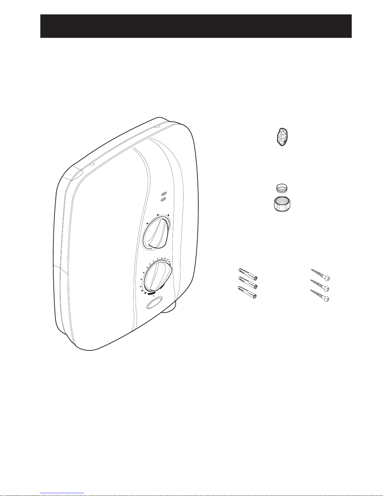
2. Documentation
1 x Installation, Operation and Maintenance Guide
1 x Installer Product Checklist
1 x Customer Support Brochure
Section
3
Pack Contents Checklist
Tick the appropriate boxes to familiarize yourself with the part names and to
confirm that the parts are included.
1. Mira Elite 2
1 x Mira Elite 2
Po
w
e
r
LO
W
Lo
w
Flo
w
M
e
d
iu
m
H
ig
h
Te
m
p
e
ra
tu
re
Sta
rt
Sto
p
3 x Wall Plug
1 x Compression Nut
1 x Olive
3 x Fixing Screws
3 x Rubber Feet
8
Power
Low Flow
Low
High
Temperature
Start Stop
Medium
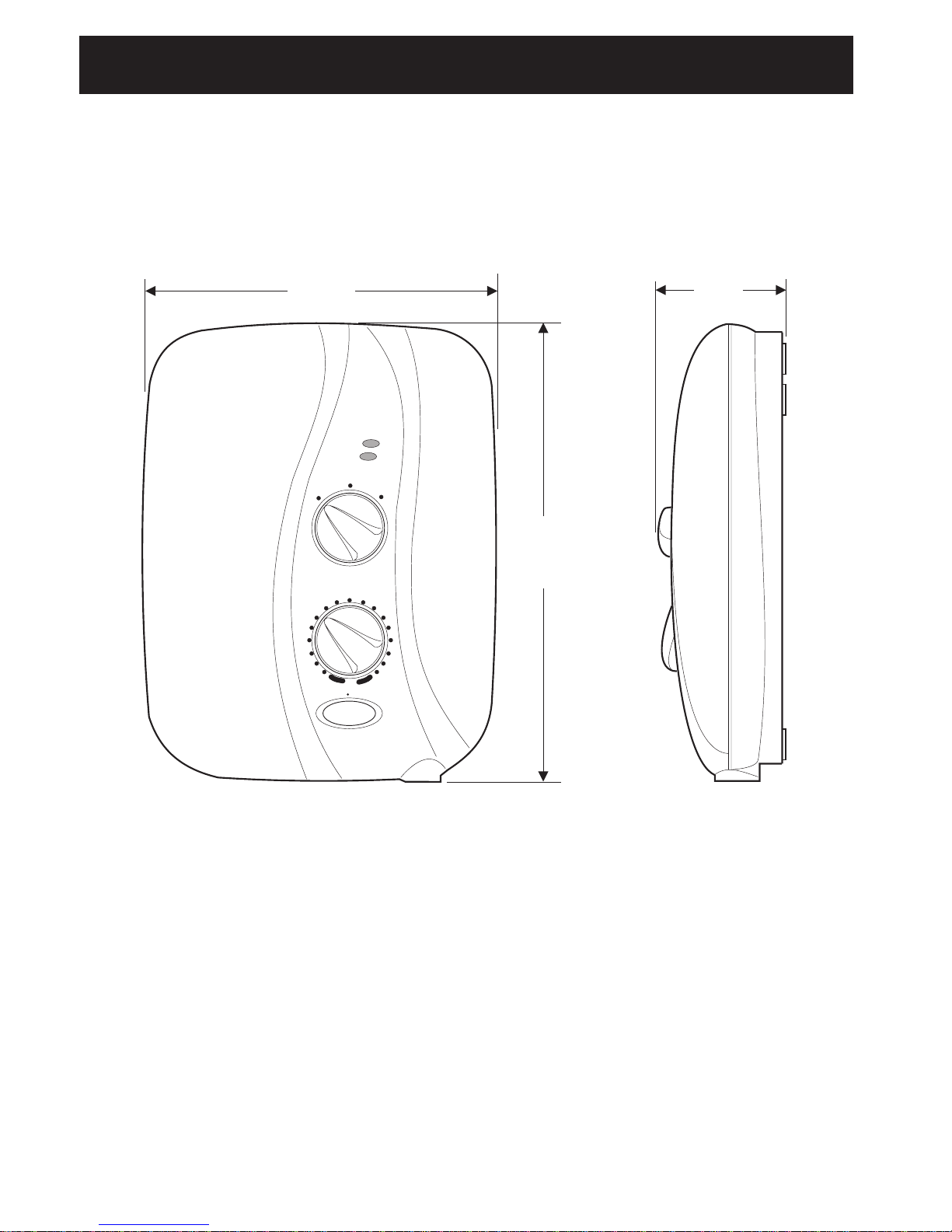
Dimensions
Section
4
270 mm 85 mm
344 mm
9
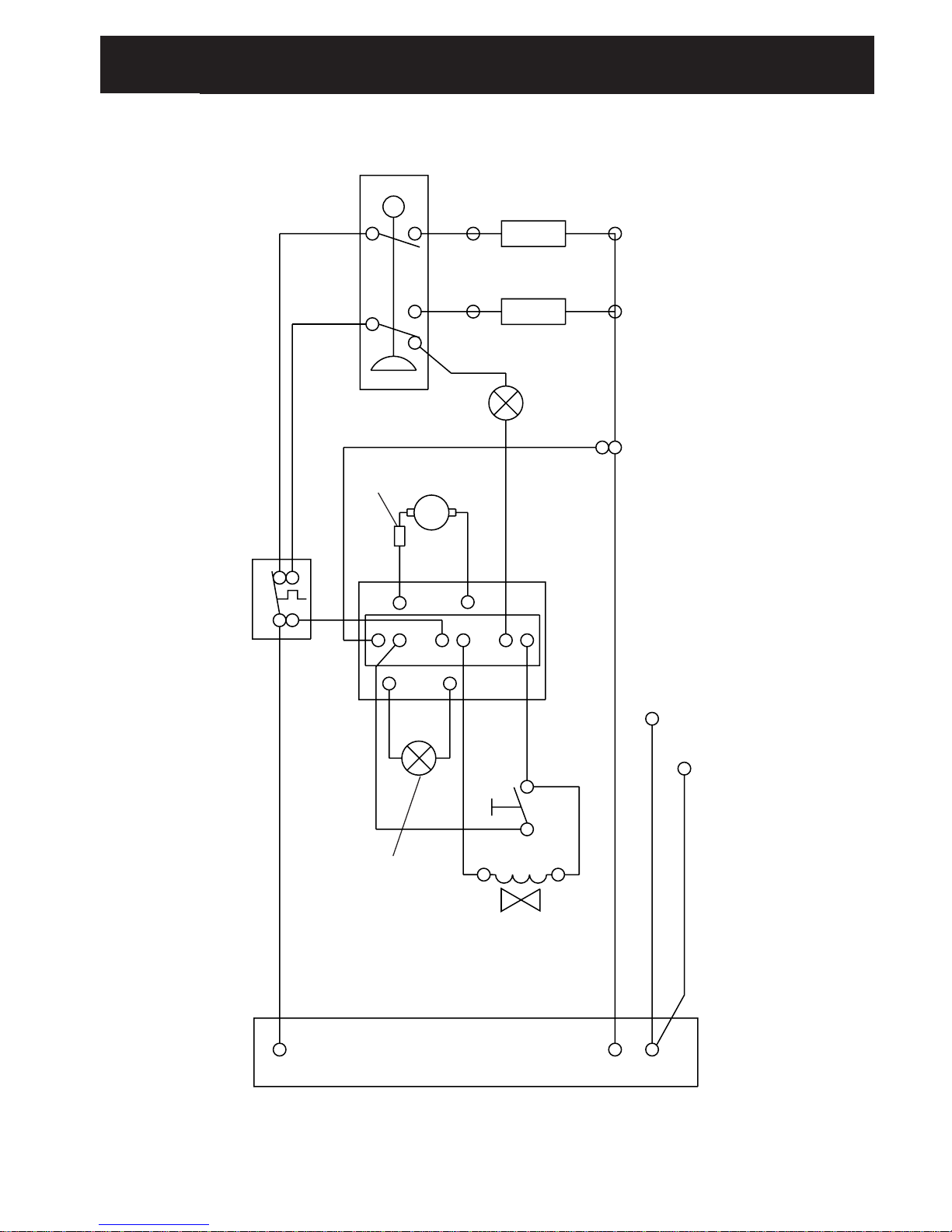
Section
Wiring Diagram
5
Pressure/Power
Selector Switch
High
Medium
Load
Low Flow
Neon
Motor
Thermal
Trip
Thermal Cutout
Dual Disc
Power On
Neon
On/Off
Solenoid Valve
Tank Connection
Inlet Connector
L
E
N
120 Brown
123 Green
122 Green
121 Blue
124 Black
128 Blue
126 Brown
130 Black
127 Brown
129 Blue
125 Black
132 Blue
131 Orange
96 Red
97 Brown
86 Brown 88 Red
1
5
4
2
37
LN

10
Section
Specifications
6
1. Plumbing
1.1. The 15 mm inlet compression connector incorporates an inlet filter, which
swivels to allow two entry positions, top and back.
1.2. The outlet terminates with a 1/2" BSP male thread for connection to a Mira
flexible shower hose.
2. Electrical
2.1. The terminal block will not accept cable larger than 16 mm
2
.
2.3. The motor is fitted with a self resetting thermal trip protection device,
designed to operate if the ambient temperatures become too high. The
maximum recommended ambient temperature for the Elite 2 is 30°C.
2.4. The following power ratings for the heater tanks are available with their
respective voltages:
Mira Elite 2 9.8 @ 240V 45 Amps
Mira Elite 2 9.0 @ 230V 40 Amps
2.5. The motor will absorb approximately 100 Watts maximum power under
normal working conditions.
3. Standards and Approvals
3.1. The Mira Elite 2 has been designed to comply with the requirements of the
British Electrotechnical Approvals Board (BEAB) and the requirements of UK
Water Regulations/Bylaws (Scotland).
3.2. This Mira Elite 2 complies with all relevant directives for CE marking.
11
Section
7
Installation Requirements
1. Plumbing
Read the section “Important Safety Information” first
1.1. The Elite 2 is designed to operate with water supply pressures from 0.008
bar (80 millimetres head) to 1 bar (10 metres head) (i.e. the vertical
distance from the base of the cold cistern to the top of the Elite 2).
However, the minimum head required will increase with pipe length and the
guide given in paragraph 1.17. should be used to ensure that adequate
head is available for any given installation.
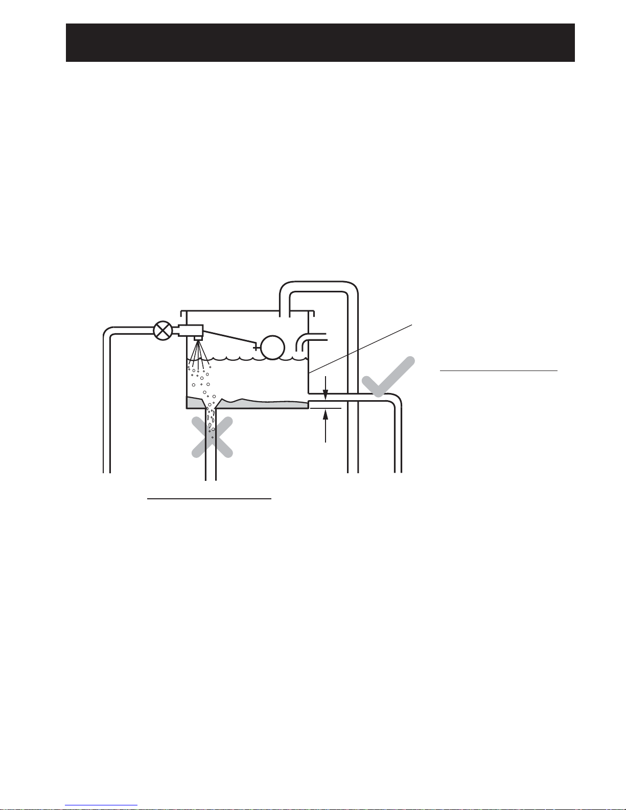
The Elite 2 MUST have its own separate supply from the cistern.
Incorrect Cistern Take Off
Debris from the bottom of the
cistern and air generated when
the cistern refills will enter the
shower supply.
Correct Cistern Take Off
Positioned away from the ball
valve, with a 25 mm distance up
from the base of the cistern.
This connection will prevent air
and debris entering the shower
supply.
25 mm
1.2. The Elite 2 is suitable for installation within the shower area and is fitted
with a pressure relief valve. It must be positioned over a water catchment
area with the controls at a convenient height. The shower fitting should be
positioned so that it discharges down the centre line of the bath, or across
the opening of a shower cubicle, and must be directed away from the
shower unit.
1.3. Use a minimum of 15 mm diameter supply pipework. It should be noted,
however, that on long pipe runs this should be increased to 22 mm (refer to
para 1.17. for guidance). When using flexible plastic pipe it is essential that
the pipe is kept flat and not looped up at any point as this may lead to air
build up which may impair performance of the shower.
25 Gallon/113 Ltr Cistern.

12
1.4. We recommend that a non restrictive (free flowing) isolating valve is fitted into
the supply from the cold water cistern, for maintenance purposes.
1.5. The Elite 2 must be fitted ONTO the finished wall surface i.e. on top of the tiles.
DO NOT block the air ventilation gaps around the sides of the unit, either by tiling
up to the sides of the unit or by using a sealant around the case. This Elite 2 is
designed to be ventilated. Failure to do this may cause product failure.
1.6. Inlet: 15 mm inlet compression connector is designed to accept plumbing
supplies from the top or back.
1.7. Back entry plumbing is accommodated without the need to recess the
15 mm inlet compression connector, enabling the wall’s surface to be completed
and sealed to prevent water ingress, before final fitting.
1.9. Use only the 15 mm inlet compression connector supplied with the Elite 2, do not
use any other types of fitting.
1.10. Outlet: 1/2" BSP male, to accept Mira flexible hose.
1.11. Refrain from applying excessive force when making connections.
Note! Excessive force on the pump housing can impair pumping
performance. Make sure that the supply pipe is trimmed and bent such that
the 15 mm inlet connector sits (or can be lightly pressed) easily on the back
of the clamp bracket prior to connection with the pump housing.
1.12. To avoid damage to the case when soldered fittings are used, pre-solder the
pipework and fittings before connecting them to the 15 mm inlet compression
connector.
1.13. Supply pipework MUST be flushed to clear debris before connecting the Elite 2.
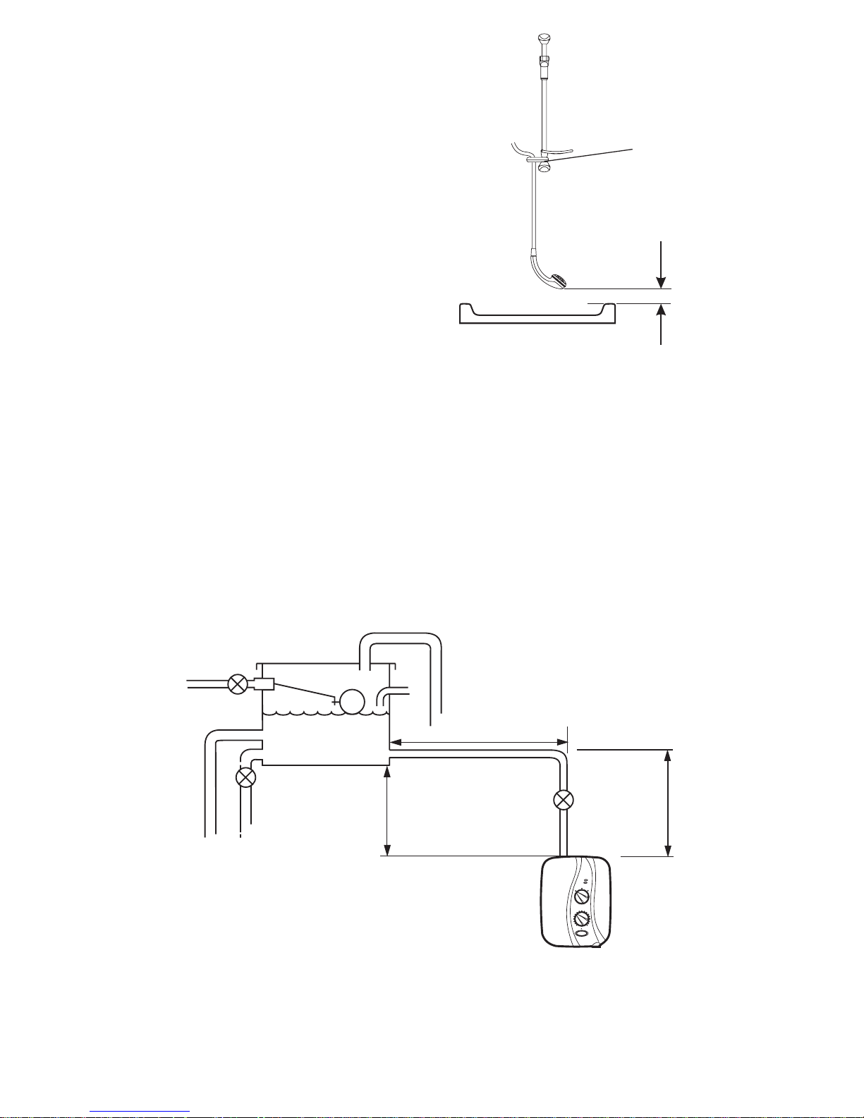
1.14. A hose retaining ring is supplied to prevent the handset from dropping below the
spillover level of the bath or shower, which could lead to contamination from backsiphonage (refer to Figure 1). The supplied hose retaining ring should meet the
great majority of user requirements for shower installations with flexible outlet
fittings. However, there will be occasions when the hose retaining ring will not
provide a suitable solution. In these instances an outlet double checkvalve, e.g.
the Mira DCV-H, must be fitted. The inclusion of the Mira DCV-H will increase
the required supply pressure typically by 0.1 bar.
Double checkvalves, fitted in the inlet supply to the appliance, cause a pressure
build-up, which could exceed the maximum static inlet pressure for the appliance.
1.8. Swivel the inlet connector assembly to suit (not directly back into the wall). Avoid
trapping the green earth bonding wire.
13
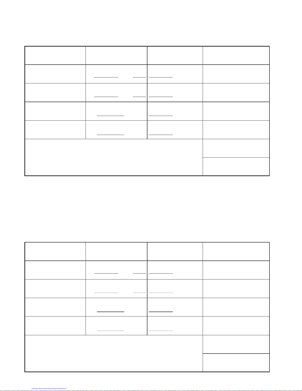
Plumbing Schematic Diagram (to be used with pipework table overleaf)
1.16. Avoid layouts where the hose will be sharply kinked. This may reduce the life of
the hose.
1.17. Long pipe runs and excessive use of 90° elbows will significantly reduce the
available head to supply the Elite 2. The pipework table should be completed to
ensure that adequate head is available for any given application.
Spill-over
Level
25 mm Minimum
Hose Retaining
Ring
1.15. When installed in very hard water
areas (above 200 ppm temporary
hardness) your installer may advise
the installation of a water treatment
device, to reduce the effects of
limescale formation. Mira Elite 2
malfunction due to excessive
limescale formation is not covered
by the manufacturer’s guarantee.
Your local water company will be
able to advise the hardness of water
in your area.
Power
LowFlow
Low
High
Temperature
Medium
Start Stop
A
B
X
Figure 1
14
The dimension (x) is calculated from the table below to give you a minimum effective
head of 80 mm which is necessary to produce a satisfactory shower in all conditions.
Pipework
Size
Quantity
Head Loss (mm)
15 mm Pipe
22 mm Pipe
15 mm Elbow
22 mm Elbow
(A) + (B)
(A) + (B)
No. Elbows
No. Elbows
x 120
x 20
x 55
x 15
80
Minimum Effective
Head
(x) mm
Size
Quantity
Head Loss (mm)
15 mm Pipe
22 mm Pipe
15 mm Elbow
22 mm Elbow
(A) + (B)
(A) + (B)
No. Elbows
No. Elbows
x 120
x 20
x 55
x 15
80
Minimum Effective
Head
(x) mm
Example! Based on the diagram Figure X with 15 mm pipework and A = 1.5 m,
B = 0.75 m.
1.5
0.75
2.25 270
1
1
55
405
 Loading...