

Mira DISCOVERY Installation Manual
1
These instructions are to be left with the user
Installation and User Guide
THERMOSTATIC MIXER
MIRA DISCOVERY

2
CONTENTS
Introduction .............................................................................................3
Patents and Design Registration ..........................................................3
Safety : Warnings ....................................................................................5
Pack Contents .........................................................................................7
Specications .......................................................................................... 9
Operating Parameters .......................................................................... 9
Installation .............................................................................................12
Suitable Plumbing Systems ................................................................12
General ...............................................................................................12
Installation Methods ...........................................................................14
Exposed Shower Control ....................................................................15
1. Rear Supplies ................................................................................. 15
2. Rising or Falling Supplies ...............................................................17
Built-in Shower Control .......................................................................19
1. Solid Wall or Stud Partition
(Using Securing Brackets - Mounting off Front Face) ................ 19
2. Solid Wall or Stud Partition
(Using Rear Fixing Points on Shower Control) ..........................22
3. Laminated Panels
(Using Securing Brackets - Mounting off Rear Face) .................24
Control Assembly ...............................................................................26
Reversed Inlet Supplies ........................................................................ 28
Operation ...............................................................................................30
Commissioning .....................................................................................31
Type 2 Valves .........................................................................................32
Fault Diagnosis ......................................................................................35
Maintenance ...........................................................................................36
Spare Parts ............................................................................................39
Accessories ...........................................................................................41
Notes ......................................................................................................42
Customer Service .................................................................................. 44

3
If you experience any difculty with the installation or operation of your new
Thermostatic Mixer, please refer to ‘Fault Diagnosis’, before contacting Kohler Mira
Ltd. Our telephone and fax numbers can be found on the back cover of this guide.
INTRODUCTION
Thank you for purchasing a quality Mira product. To enjoy the full potential of your
new product, please take time to read this guide thoroughly, having done so, keep
it handy for future reference.
The Mira Discovery Thermostatic Mixer is a Thermostatic Shower Control with
separate ow and temperature controls.
A 12 L/Min ow regulator is supplied for high pressure systems to reduce excessive
shower force.
Note! The tting of any ow regulator will invalidate TMV2 compliance due to the
minimum ow rate requirements. Do not t ow regulators in TMV2 applications.
The Thermostatic Mixer incorporates a wax capsule temperature sensing unit, which
provides an almost immediate response to changes in pressures or temperature of
the incoming water supplies to maintain the selected temperature. An adjustable
maximum temperature stop is provided which limits the temperature to a safe level.
Inlet Filters are tted to protect the thermostatic cartridge.
Mira Discovery Exposed: Thermostatic Mixer for connection to rising, falling or rear
entry pipework, supplied complete with Mira Discovery Shower Fittings.
Mira Discovery Built-in: Thermostatic Mixer for connection to concealed pipework,
supplied complete with Mira Discovery Shower Fittings.
This product has been certied as a Type 2 valve under the BUILDCERT TMV2
scheme. This product also complies with the Water Supply (water ttings) Regulations
1999.
Patents and Design Registration
Patents: GB: 2 291 693, 2 392 225, 2 421 297
Euro: 1 672 257 DE FR GB IT NL SE
Germany: 695 13 455.8
France: 0 694 721
USA: 7 240 850
Patent Applications: Euro: 03254070.0
USA: 2006-0124758-A1, 11/804 631
Design Registration 000351887-0001-0006

4
Guarantee
For domestic installations, Mira Showers guarantee the Mira Discovery against
any defect in materials or workmanship for a period of three years from the date of
purchase (shower ttings for one year).
For non-domestic installations, Mira Showers guarantee the Mira Discovery
against any defect in materials or workmanship for a period of one year from the
date of purchase.
For terms and conditions refer to the back cover of this guide.
Recommended Usage
Application Valve Only Valve with Fittings
Domestic
Light Commercial
Heavy Commercial
Healthcare

5
SAFETY : WARNINGS
The function of a thermostatic mixing valve is to deliver water consistently at a safe
temperature. In keeping with every other mechanism, it cannot be considered as
functionally infallible and as such, cannot totally replace a supervisor’s vigilance where
that is necessary. Provided it is installed, commissioned, operated and maintained
within manufacturers recommendations, the risk of failure, if not eliminated, is reduced
to the minimum achievable.
Mira thermostatic mixers are precision engineered and should give continued safe
and controlled performance, provided:
1. They are installed, commissioned, operated and maintained in accordance with
manufacturers recommendations.
2. Periodic attention is given, when necessary, to maintain the product in good
functional order.
Caution!
1. Read all of these instructions.
2. Retain this guide for later use.
3. Pass on this guide in the event of change of ownership of the installation
site.
4. Make sure that you fully understand how to operate this shower and make sure
that it is properly maintained in accordance with the instructions given in this
manual.
5. Follow all warnings, cautions and instructions contained in this guide.
6. Do not install the product in a position in which service access is restricted.
7. Anyone who may have difculty understanding or operating the controls of any
shower should be attended whilst showering. Particular consideration should
be given to:
7.1. The young.
7.2. The elderly.
7.3. The inrm.
7.4. The disabled.
7.5. Anyone who suffers from a medical condition that can result in temporary
incapacity (e.g. epilepsy or blackouts).
7.6. anyone inexperienced in the correct operation of the controls.
8. This appliance is not intended for use by persons (including children) with
reduced physical, sensory or mental capabilities, or lack of experience and
knowledge, unless they have been given supervision or instruction concerning
the use of the appliance by a person responsible for their safety.
9. Children should be supervised to make sure that they do not play with the
appliance.

6
10. Care is required when adjusting ow or temperature, make sure that the
temperature has stabilised. Rapid/excessive movement of the ow and/
or temperature control levers may result in momentary changes in blend
temperature.
11. When this product has reached the end of its serviceable life, it should be
disposed of in a safe manner, in accordance with current local authority
recycling, or waste disposal policy.
12. Type 2 Valves are only used for applications covered by their approved
designations, refer to section: ‘Type 2 Valves’.
7
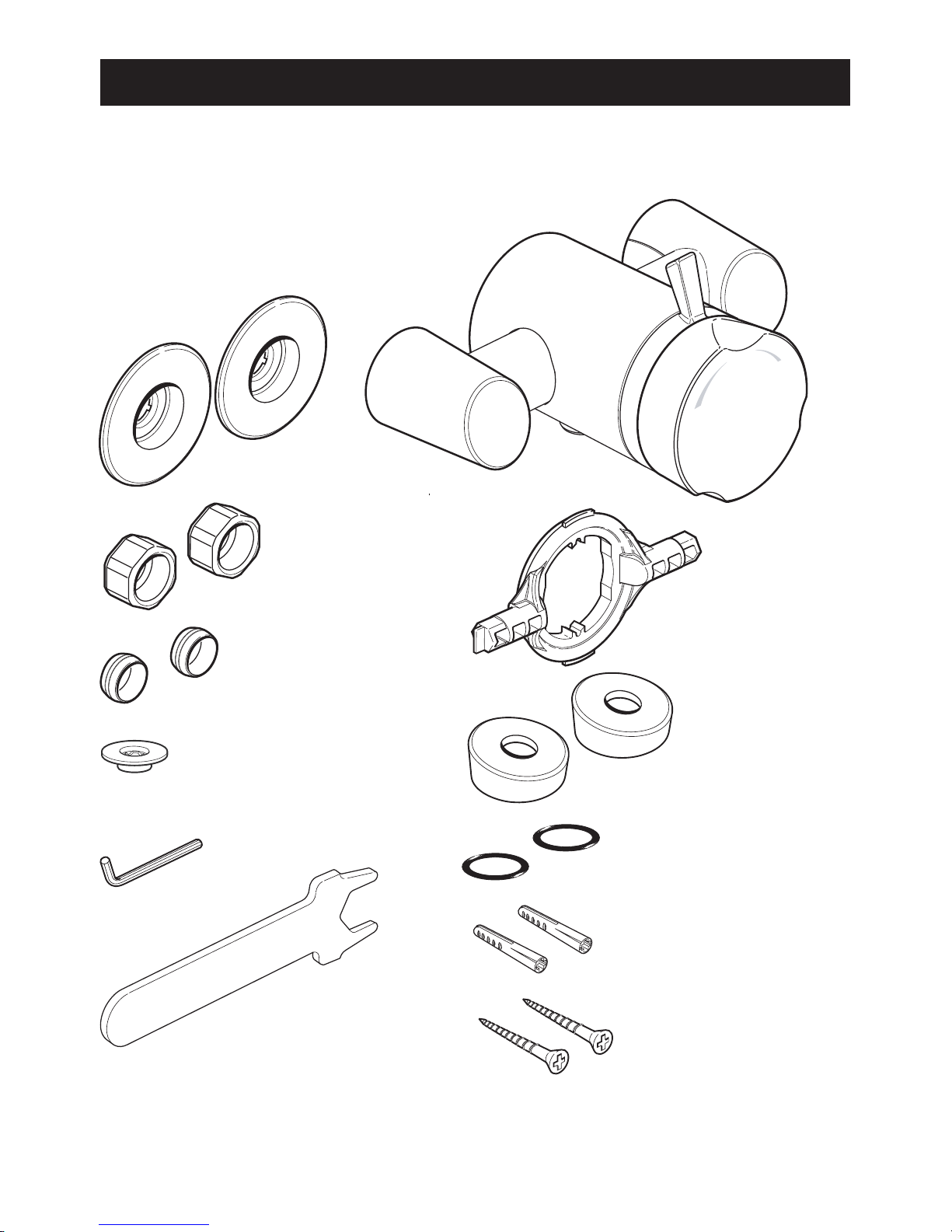
1 x Mira Discovery Thermostatic Mixer
2 x Concealing Plates
2 x 15 mm Compression Nuts
2 x 15 mm Olives
1 x 2.5 mm Hexagon Key
1 x O-Key
2 x Concealing Caps
2 x Wall Plugs
2 x Securing Screws
2 x Concealing Cap Seals
1 x Guarantee Registration Document
1 x Installation Template
1 x 24 mm Spanner
PACK CONTENTS
Tick the appropriate boxes to familiarise yourself with the part names and to conrm
that the parts are included.
Exposed Discovery Thermostatic Mixer
1 x 12 L/Min Flow Regulator
(Note! see section: Type
2 Valves - Application)
8
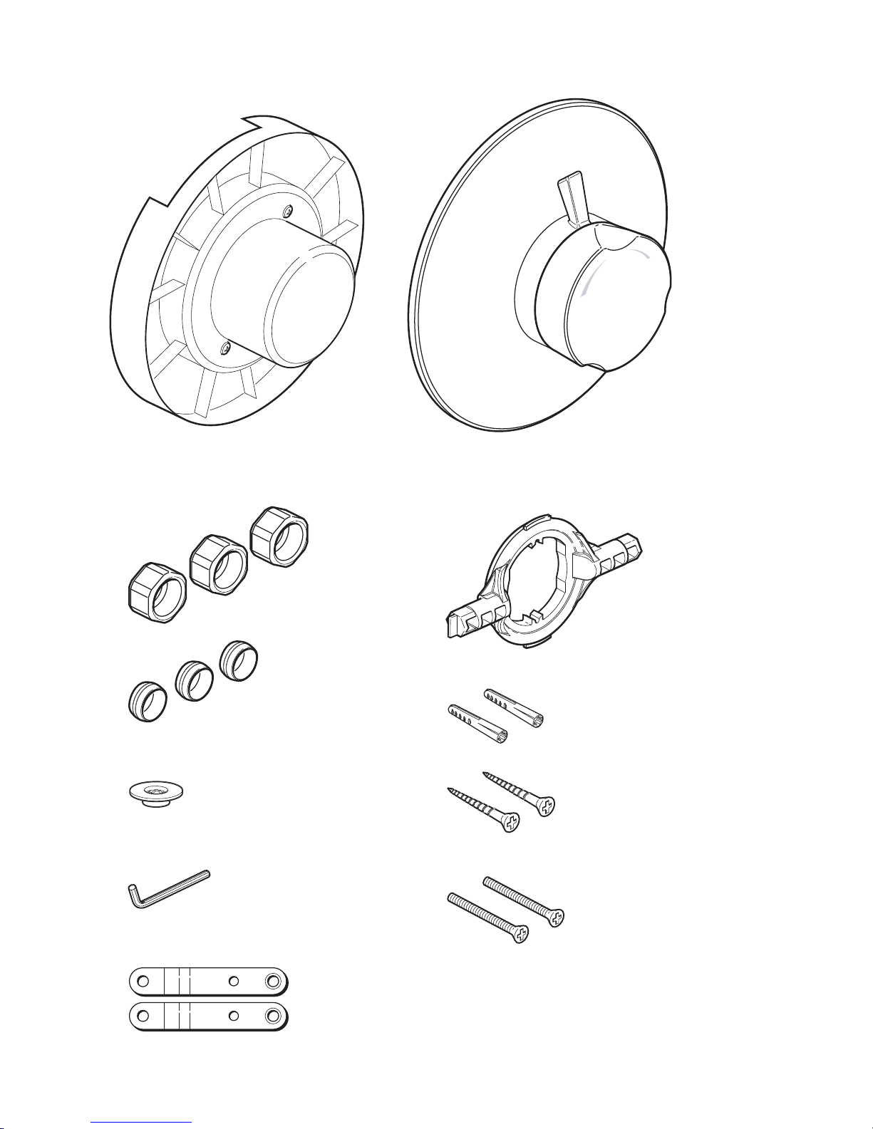
Built-in Discovery Thermostatic Mixer
1 x Control Assembly
3 x 15 mm
Compression Nuts
3 x 15 mm Olives
1 x 2.5 mm Hexagon Key
1 x O-Key
2 x Wall Plugs
2 x Securing Screws
1 x Mira Discovery Thermostatic Mixer
(attached to the Building-in Shroud)
1 x Guarantee Registration Document
2 x Securing Brackets
2 x M5 x 40 Screws
1 x 12 L/Min Flow Regulator
(Note! see section: Type
2 Valves - Application)

9
SPECIFICATIONS
Operating Parameters
For Type 2 valves, the supply conditions specied in section: ‘Type 2 Valves Application’ take precedence over the operating parameters which follow.
Pressures
• Max Static Pressure: 10 Bar.
• Max Maintained Pressure: 5 Bar.
• Min Maintained Pressure (Gravity System): 0.1 Bar. (0.1 bar = 1 Metre head
from cold tank base to shower handset outlet).
Note! For gravity fed / other low pressure systems (0.5 bar or below) do not t the
ow regulator.
For optimum performance supplies should be nominally equal.
Flow Regulator Installation
Flow regulators are supplied with this product and should be tted in high
pressure systems to either;
• Reduce excessive force and ow rate.
• Reduce noise through the mixer due to high or unequal pressures.
• Stabilise incoming supply temperatures.
Important! The tting of ow regulators will invalidate any TMV2 compliance
due to minimum ow rate requirements. Do not t the ow regulator in TMV2.
applications.
Temperatures
• Factory Pre-set (Blend) Shower: 43°C.
• Optimum Thermostatic Control Range: 35°C to 43°C (achieved with supplies
of 15°C cold, 65°C hot and nominally equal pressures).
• Recommended Hot Supply: 60°C to 65°C Note! The mixing valve can
operate at higher temperatures for short periods without damage, however
this could detrimentally affect thermostatic performance. For safety and
performance reasons it is recommended that the maximum hot water
temperature is limited to 65°C.
• Cold Water Range: up to 25°C.
• Minimum Recommended Differential between Hot Supply and Outlet
Temperature: 12°C.
10
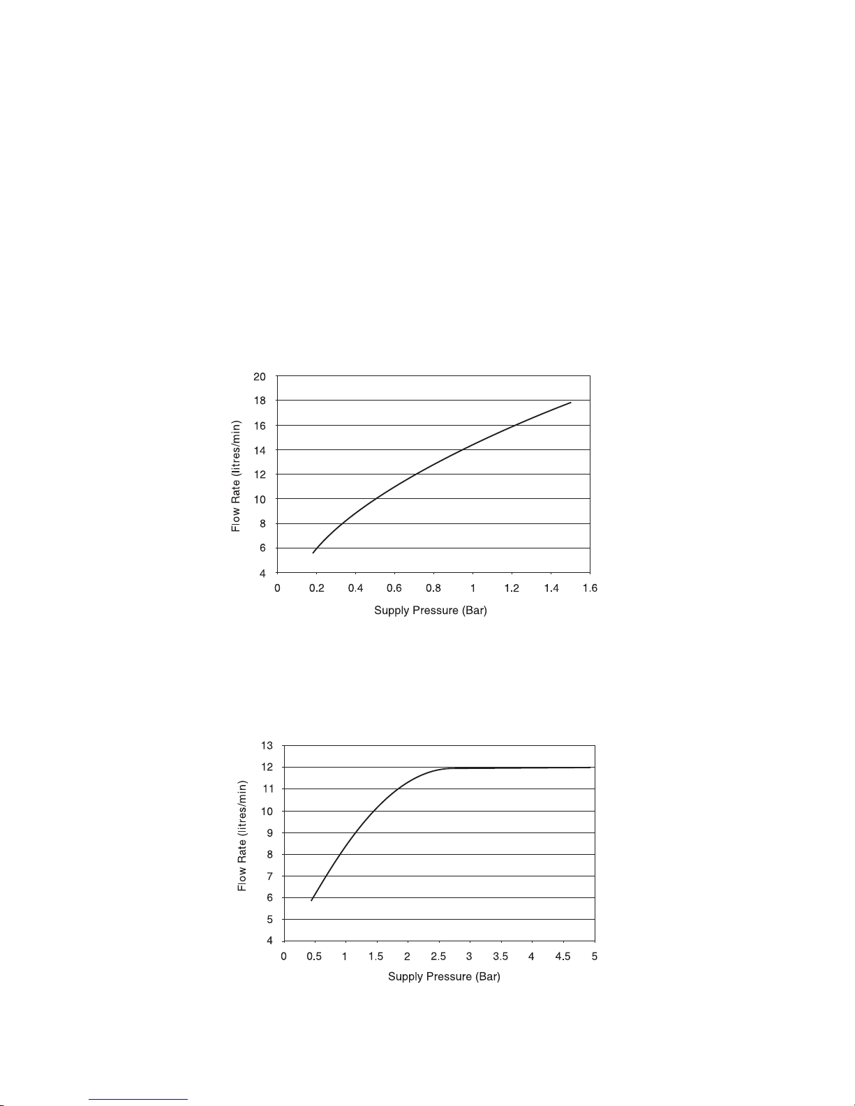
Flow Rates
Typical Flow Rates on Low Pressure Systems - Mira Discovery with Adjustable
Fittings or Rigid Head:
Typical Flow Rates on High Pressure Systems (with 12 Litres/Min Flow Regulator
tted in shower control outlet) - Mira Discovery with Adjustable Fittings or Rigid
Head:
Thermostatic Shut-down
• For safety and comfort the thermostat will shut off the mixing valve within
2 Seconds if either supply fails (achieved only if the blend temperature has a
minimum differential of 12°C from either supply temperature).
Connections
• Inlets: 15 mm Compression.
• Outlet: ½” BSP Flat Face / 15 mm Compression
• Standard connections are: hot - left, cold - right, outlet - bottom (EV mod-
els), top (BIV models).
11
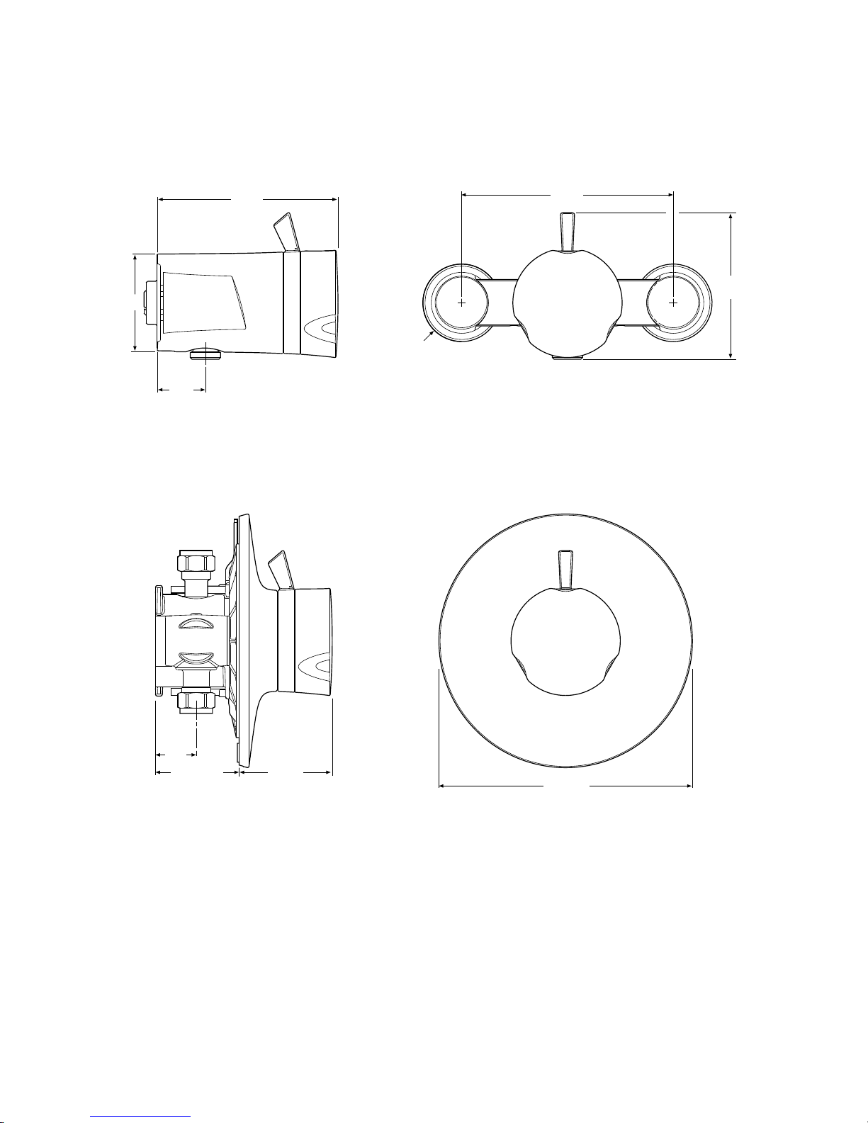
Dimensions
Built-in Discovery Shower Control
153
106
131
35
70
Ø56
Exposed Discovery Shower Control
Dimensions in mm
67
67 - 85
30
Ø183
Building-in Depth

12
INSTALLATION
Suitable Plumbing Systems
Gravity Fed:
The thermostatic mixer must be fed from a cold water cistern (usually tted in the
loft space) and a hot water cylinder (usually tted in the airing cupboard) providing
nominally equal pressures.
Mains Pressurised Instantaneous Hot Water System (Combination Boiler):
The thermostatic mixer can be installed with systems of this type with balanced
pressures. (Recommended Minimum Maintained Pressure: 1.0 Bar).
Unvented Mains Pressure System:
The thermostatic mixer can be installed with an unvented, stored hot water
system.
Pumped System:
The thermostatic mixer can be installed with an inlet pump (twin impeller). The pump
must be installed in a suitable location and in accordance with its instructions.
General
Installation must be carried out in accordance with these instructions, and must be
conducted by designated, qualied and competent personnel.
The installation must comply with the requirements of UK Water Regulations/Bye-
laws (Scotland), Building or any particular regulations and practices, specied by
the local water company or water undertakers.
Note! Make sure that all site requirements correspond to the information given in the
section: ‘Specications’. For Type 2 valves see also supply conditions in section:
‘Type 2 Valves’.
1. The mixer must not be installed in an area where it may freeze.
2. The mixer must be tted to a tiled or sealed nished surface
3. For stud partitions alternative xings may be required.
4. Isolating valves must be installed close to the mixer for ease of
maintenance.
5. Pipework must be rigidly supported and avoid any strain on the connections.
6. Pipework dead-legs should be kept to a minimum.
7. If pipework enters the shower from the rear through a hole in the wall . Provision
must be made to prevent water ingress back into the wall structure.
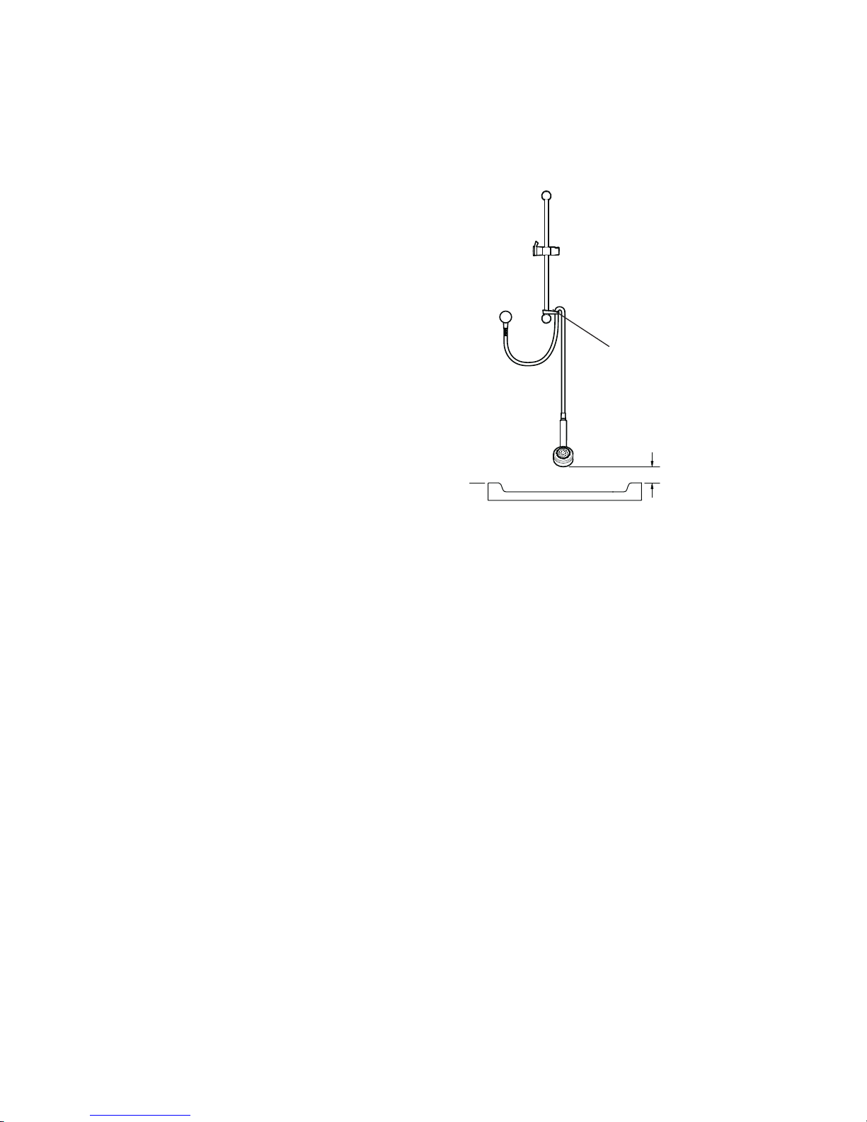
13
Hose Retaining Ring
25 mm Minimum
Spill-over Level
8. The water supplies to this product must be isolated if the product is not to be
used for a long period of time. If the product or pipework is at risk of freezing
during this period they should also be drained of water.
9. All pipework must be checked for leaks before the product installation is
completed. The mixer should be pressurised and the inlet & outlet connections
inspected. If the mixer is dismantled
during installation or servicing then
upon completion the product must
be inspected to ensure there are no
leaks
10. Decide on a suitable position for the
mixer. The position of the mixer and
the Shower Fittings must provide a
minimum gap of 25 mm between the
spill-over level of the shower tray/bath
and the handset (refer to illustration).
This is to prevent back-siphonage. For
further information on the installation
of your Shower Fittings, refer to the
Fittings Installation and User Guide.
Note! Only use Shower Fittings
recommended by the manufacturer or supplier.
11. Do Not overtighten grubscrews as product damage may occur. Use hexagonal
key provided and hand tighten only, do not use power tools.
12. Having completed the installation, make sure that the user is familiar with the
operation of the mixer and that this guide is left with the user.
14
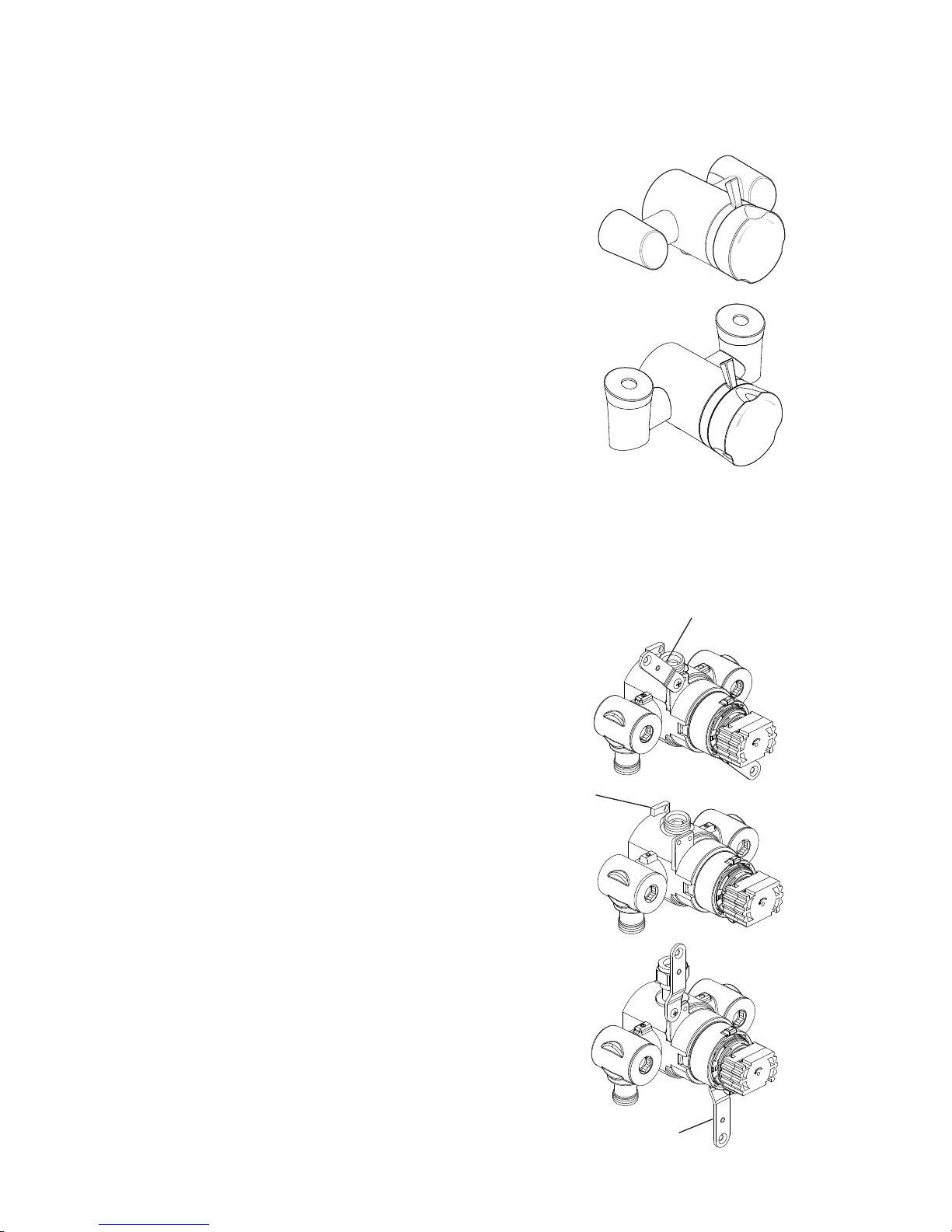
Installation Methods
Exposed Discovery Shower Control
The Exposed Discovery Shower Control
can be installed with Rear, Rising or Falling
Supply Inlets.
For Rear Entry Supplies, go to section:
‘Exposed Shower Control, 1. Rear
Supplies’.
For Rising or Falling Supplies, go to
section: ‘Exposed Shower Control, 2.
Rising or Falling Supplies’.
Built-in Discovery Shower Control
The Built-in Discovery Shower Control
can be installed using Rear Fixing Points
on the Body, or by using the Securing
Brackets (supplied) on the Front Face of a
Solid Wall or Stud Partition, or on the Rear
Face of a Laminated Panel.
For installation into a Solid Wall or Stud
Partition using the Securing Brackets,
go to section: ‘Built-in Shower Control,
1. Solid Wall or Stud Partition (Using
Securing Brackets - Mounting off Front
Face)’.
For installation into a Solid Wall or
Stud Partition using the Rear Fixing
Points, go to section: ‘Built-in Shower
Control, 2. Solid Wall or Stud Partition
(Using Rear Fixing Points on Shower
Control)’.
For installation behind a Laminated Panel
using the Securing Brackets, go to section:
‘Built-in Shower Control, 3. Laminated
Panel (Using Securing Brackets Mounting off Rear Face)’.
Rear Fixing
Points
Securing Brackets
(Front Face)
Securing Brackets
(Rear Face)
 Loading...