

Mira Coda Plus User Manual
1
These instructions must be left with the user.
Installation & User Guide
MIRA CODA PLUS
CODA PLUS
THERMOSTATIC BAR VALVE

2
CONTENTS
Introduction .............................................................................................3
Guarantee ............................................................................................4
Recommended Usage ..........................................................................4
Patent Application:................................................................................4
Safety : Warnings .................................................................................... 5
Pack Contents .........................................................................................6
Specications ..........................................................................................7
Pressures ............................................................................................. 7
Temperatures .......................................................................................7
Thermostatic Shut-down ......................................................................7
Connections .........................................................................................7
Dimensions ...........................................................................................7
Installation ...............................................................................................8
Suitable Plumbing Systems ..................................................................8
General .................................................................................................8
Installation .......................................................................................... 10
Installation with Fixed Pipework ......................................................... 15
Commissioning .....................................................................................17
Maximum Temperature Setting ..........................................................17
Operation ...............................................................................................18
Adjusting the Temperature .................................................................18
Adjusting the Flow ..............................................................................18
Maintenance ........................................................................................... 19
Fault Diagnosis ...................................................................................19
Lubricants ...........................................................................................20
Cleaning ............................................................................................. 20
Bar Valve Removal .............................................................................20
Maintaining the Non-Return Valves ....................................................21
Spare Parts ............................................................................................22
Accessories ...........................................................................................23
Customer Service ....................................................................Back Page

3
INTRODUCTION
Thank you for purchasing a quality Mira product. To enjoy the full potential of your
new product, please take time to read this guide thoroughly, having done so, keep
it handy for future reference.
The Mira Coda Plus thermostatic bar valve is a shower control designed for wall
mount installations.
The thermostatic bar valve has two knobs, one knob controls the ow and the other
knob controls the temperature.
The thermostatic bar valve incorporates a wax capsule temperature sensing
unit, which provides an almost immediate response to changes in pressures or
temperature of the incoming water supplies, to maintain the selected temperature.
An adjustable maximum temperature stop is provided which limits the temperature
to a safe level. Inlet lters are tted to protect the thermostatic cartridge.
The Mira Coda Plus is supplied complete with a patent applied for xing kit which
has been designed to make the installation of bar valves easier and more secure
and has the following benets over traditional ‘Z’ connectors:
Water connections are made in front of the nished wall surface•
Easy centre and levelling adjustment•
Foam seal to prevent water ingress•
Bar valve is secured to the wall•
Suitable for any bar valve using 3/4” female threads•
Can be used on plastic barrier pipes (with suitable pipe insert)•
If you experience any difculty with the installation or operation of your new
Thermostatic Mixer, please refer to ‘Fault Diagnosis’, before contacting Mira
Showers. Our contact details can be found on the back cover of this guide.

4
Guarantee
For domestic installations, Mira Showers guarantee the Mira Coda Plus against
any defect in materials or workmanship for a period of ve years from the date of
purchase (shower ttings for one year).
For non-domestic installations, Mira Showers guarantee the Mira Coda Plus
against any defect in materials or workmanship for a period of one year from the
date of purchase.
For terms and conditions refer to the back cover of this guide.
Recommended Usage
Application Valve with Fittings
Domestic
ü
Light Commercial
ü
Heavy Commercial
û
Healthcare
û
Patent Application:
GB 0818001.0

5
SAFETY : WARNINGS
The function of a thermostatic mixing valve is to deliver water consistently at a safe
temperature. In keeping with every other mechanism, it cannot be considered as
functionally infallible and as such, cannot totally replace a supervisor’s vigilance where
that is necessary. Provided it is installed, commissioned, operated and maintained
within manufacturers recommendations, the risk of failure, if not eliminated, is reduced
to the minimum achievable.
Mira thermostatic mixers are precision engineered and should give continued safe
and controlled performance, provided:
1. They are installed, commissioned, operated and maintained in accordance with
the manufacturer’s recommendations.
2. Periodic attention is given, when necessary, to maintain the product in good
functional order.
Caution!
1. Read all of these instructions.
2. Retain this guide for later use.
3. Pass on this guide in the event of change of ownership of the installation
site.
4. Follow all warnings, cautions and instructions contained in this guide.
5. Anyone who may have difculty understanding or operating the controls of any
shower should be attended whilst showering. Particular consideration should
be given to the young, the elderly, the inrm or anyone inexperienced in the
correct operation of the controls.
6. When this product has reached the end of its serviceable life, it should be
disposed of in a safe manner, in accordance with current local authority
recycling, or waste disposal policy.

6
(Ø6 mm) (Ø6 mm)
(Ø6 mm) (Ø6 mm)
Refer to the installation guide supplied
for full installation instructions
Make sure that the supply pipes are thoroughly flushed
through before connection to the shower control
6.1712.029.2.0
Allow 100 mm
Minimum to Wall
Allow 100 mm
Minimum to Wall
Hot Supply Inlet
(Ø19 mm)
150 mm Pipe Centres
Cold Supply Inlet
(Ø19 mm)
Bar Valve Fixing Kit
Installation Template
PACK CONTENTS
Tick the appropriate boxes to familiarise yourself with the part names and to conrm
that the parts are included.
Documentation
q 1 x Guarantee Registration Document
q 1 x Mira Coda Bar Valve
Bar Valve Fixing Kit
q 2 x Wall Plugs
q 2 x Fixing Screws
q 2 x Backplates
q 2 x Olives
q 2 x Nuts
q 2 x Offset Connectors
q 4 x Screws
q 2 x Washers / Filters
q 2 x Concealing Plates
q 1 x Plastic Pipe Guide
q 1 x Installation Template
q 2 x Locking Rings (only required in certain installations)

7
SPECIFICATIONS
Pressures
Max Static Pressure: • 10 Bar.
Max Maintained Pressure: • 5 Bar.
Min Maintained Pressure: (Gas Water Heater): • 1.0 Bar. (for optimum
performance supplies should be nominally equal.)
Min Maintained Pressure (Gravity System): • 0.1 Bar. (0.1 bar = 1 Metre head
from cold tank base to shower handset outlet.)
Temperatures
Close temperature control is provided between • 20°C and 50°C.
Optimum Thermostatic Control Range: • 35°C to 45°C. (achieved with supplies
of 15°C cold, 65°C hot and nominally equal pressures.)
Recommended Hot Supply: • 60°C to 65°C. (Note! The mixing valve can operate
at temperatures up to 85°C for short periods without damage. However for
safety reasons it is recommended that the maximum hot water temperature is
limited to 65°C.)
Minimum Recommended Differential between Hot Supply and Outlet •
Temperature: 10°C.
Cold Water Range: up to• 25°C.
Thermostatic Shut-down
For safety and comfort the thermostat will shut off the mixing valve • within
2 Seconds if either supply fails (achieved only if the blend temperature has a
minimum differential of 12°C from either supply temperature).
Connections
Hot: Left • (side nearest ow control), 15 mm compression.
Cold: Right • (side nearest temperature control), 15 mm compression.
Outlet: Bottom• , ½” BSP Male to exible hose.
Note! This product does not allow for reversed inlets and will deliver unstable
temperatures if tted incorrectly.
8
INSTALLATION
Suitable Plumbing Systems
Gravity Fed:
The thermostatic mixer must be fed from a cold water cistern (usually tted in the
loft space) and a hot water cylinder (usually tted in the airing cupboard) providing
nominally equal pressures.
Gas Heated System:
The thermostatic mixer can be installed with a combination boiler.
Unvented Mains Pressure System:
The thermostatic mixer can be installed with an unvented, stored hot water
system.
Mains Pressurised Instantaneous Hot Water System:
The thermostatic mixer can be installed with systems of this type with balanced
pressures.
Pumped System:
The thermostatic mixer can be installed with an inlet pump (twin impeller). The pump
must be installed on the oor next to the hot water cylinder.
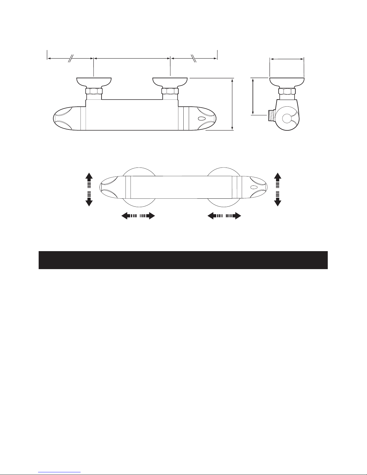
150 ± 5
100
80
70
All dimensions in mm
115 Min to Wall100 Min to Wall
Dimensions
5 mm 5 mm
5 mm 5 mm
Adjustment
 Loading...