

Mira Agile S B97C, Agile S Eco B97C, Agile Store EV+ B97D, Agile EV+ B97C, Agile ERD+ B97D Installation Manual
...
Mira Agile S Eco, Mira Agile S, Mira Agile ERD+
Mira Agile Sense ERD+, Mira Agile Store EV+, Mira Agile EV+
Installation and User Guide
These instructions must be left with the user
1
For SPARES,
ADVICE or REPAIRS
please call us free
on 0800 001 4040
(UK only)
1285246-W2-D
Introduction
Thank you for choosing a Mira shower. To enjoy the full potential of your new shower,
please take time to read this guide thoroughly, and keep it handy for future reference.
Products manufactured by Kohler Mira Ltd are designed to be safe, provided that they are
installed, used and maintained in good working order, in accordance with our instructions
and recommendations.
Follow all warnings, cautions and instructions contained in this guide, and on, or inside the
shower. This guide is also available in digital format from our website or by contacting our
customer services department.
This product should not be disposed of with your general household waste. When this product
has reached the end of its serviceable life please take it to a recognised facility such as your
local civic amenity site for recycling. Your local authority or retailer will be able to advise you
of your nearest recycling facility.
Type 2 Valves
This product has been certied as a Type 2 valve. It also complies with the Water Supply
(water ttings) regulations 1999. For further information on Type 2 Valves, refer to the TMV2
Requirements Manual (this is available to view or download from our website www.
mirashowers.com).
The approved designation for this product is listed in the table below.
Mira Mixer Showers covered by this guide:
Product
Mira Agile S
Mira Agile S Eco
Mira Agile EV+
Mira Agile ERD+
Mira Agile Sense ERD+
Mira Agile Store EV+
Model
Number
B97C Chrome HP-S, HP-SE, LP-S
B97D Chrome HP-S, HP-SE, LP-S
Colour Type 2 Designation
Guarantee
This product has been designed for domestic use only, Mira Showers guarantee this product
against any defect in materials or workmanship for a period of ve years from the date of
purchase (shower ttings for one year).
Failure to follow the instructions provided with the shower will invalidate the guarantee
For terms and conditions, refer to the back cover of this guide.
Recommended Usage
Recommended Usage
Domestic
Heavy Commercial
1285246-W2-D
Light Commercial
Healthcare
2
Design Registration & Patents
Design Registration:
001312649-0001 to 001312649-0022
Patents:
GB 2 422 886, 2 491 044, 2 500 948, 2 544 770
Euro: 1 672 257, 2 710 194, DE, FR, GB, IT, NL, SE
USA: 8 167 215, 8 517 282
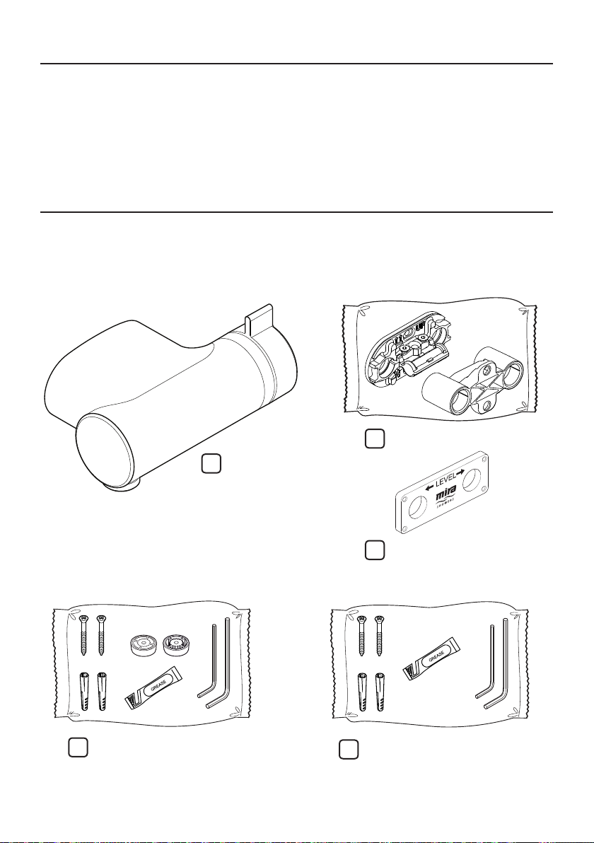
Pack Contents
Agile S
Agile S Eco
Agile EV+
1 x Wallplate Pack
1 x Shower Unit
Agile S & Agile EV+ Agile S Eco
1 x Component Pack
(2 x Screws, 2 x Wall Plugs, 2 x Flow Reg,
2 x Hex Key, 1 x Grease Sachet)
3
1 x Component Pack
(2 x Screws, 2 x Wall Plugs, 2 x Hex Key,
1 x Grease Sachet)
1 x First Fix Pipe Guide
1285246-W2-D
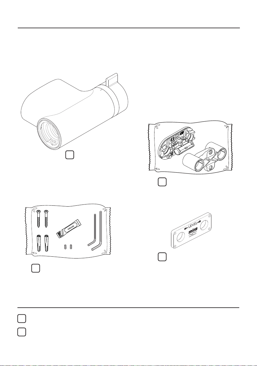
Pack Contents
Agile ERD+
Agile Sense ERD+
Agile Store EV+
1 x Shower Unit
1 x Wallplate Pack
1 x Component Pack
(2 x Screws, 2 x Wall Plugs, 2 x Hex Key,
1 x Grease Sachet, 2 x Grubscrew - 1 as
a spare)
Documents
1 x Installation & User Guide
1 x Guarantee Card
1285246-W2-D
1 x First Fix Pipe Guide
4

Important Safety Information
WARNING ! This shower can deliver scalding temperatures. For
continued safe operation, follow all instructions, warnings and
cautions contained in this guide and on or inside the shower.
Periodic maintenance may be required to keep the product in
good working order.
The function of a thermostatic mixing valve is to deliver water
consistently at a safe temperature. In keeping with every other
mechanism, it cannot be considered as functionally infallible and
as such, cannot totally replace a supervisor’s vigilance where that
is necessary. Provided it is installed, commissioned, operated and
maintained within manufacturers recommendations, the risk of
failure, if not eliminated, is reduced to the minimum achievable.
PLEASE OBSERVE THE FOLLOWING TO REDUCE THE RISK
OF INJURY:
INSTALLING THE SHOWER
1. I nstallation of the shower must be carried out in accordance with
these instructions by qualied, competent personnel. Read all
instructions before installing the shower.
2 . DO NOT install the shower where it may be exposed to freezing
conditions. Ensure that any pipework that could become frozen is
properly insulated.
3 . DO NOT perform any unspecied modications to the shower
or its accessories. When servicing only use genuine Kohler Mira
replacement parts.
4 . If the shower is dismantled during installation or servicing then, upon
completion, an inspection must be made to ensure all connections
are tight and that there are no leaks.
USING THE SHOWER
5 . The shower must be operated and maintained in accordance with
the requirements of this guide. Make sure you fully understand how
to operate the shower before use, read all instructions and retain
this guide for future reference.
5
1285246-W2-D

6. DO NOT switch the shower on if there is a possibility that the water
in the shower unit or ttings is frozen.
7 . The shower can be used by children aged from 8 years and above
and persons with reduced physical, sensory or mental capabilities
or lack of experience and knowledge if they have been given
supervision or instruction concerning use of the appliance in a safe
way and understand the hazards involved. Children must not be
allowed to play with the shower.
8 . Anyone who may have diculty understanding or operating the
controls of any shower should be attended whilst showering.
Particular consideration should be given to the young, the elderly,
the inrm or anyone inexperienced in the correct operation of the
controls.
9. DO NOT allow children to clean or perform any user maintenance
to the shower unit without supervision.
10. Always check the water temperature is safe before entering the
shower.
1 1 . DO NOT adjust the temperature control rapidly while using the
shower.
12. Use caution when altering the water temperature while in use,
always check the temperature before continuing to shower.
13. DO NOT switch the shower o and back on while standing in the
water ow.
14. DO NOT t any form of outlet ow control. Only Mira recommended
outlet ttings should be used.
1 5 . The showerhead must be descaled regularly. Any blockage of the
showerhead or hose may aect showering performance.
1 6 . The water supplies to this product must be isolated if the product is
not to be used for a long period of time. If the product or pipework
is at risk of freezing during this period they should also be drained
of water.
1 7 . When this product has reached the end of its serviceable life, it
should be disposed of in a safe manner, in accordance with current
local authority recycling, or waste disposal policy.
1285246-W2-D
6

Specications
For Type 2 Valves, the supply conditions specied in the TMV2 Requirements Manual take
precedence over the operating parameters which follow.
Pressures
• Max Static Pressure: 10 Bar.
• Max Maintained Pressure: 5 Bar.
• Min Maintained Pressure (Gravity System): 0.1 Bar (0.5 Bar for models with Eco
Showerhead). (0.1 bar = 1 Metre head from cold tank base to showerhead outlet).
Note: For gravity fed or other low pressure systems (0.5 bar or below) do not t the outlet
ow regulator (where applicable).
• For optimum performance supplies should be nominally equal.
Temperatures
• Factory Pre-set (Blend) Shower: 43° C.
• Optimum Thermostatic Control Range: 35° C to 45° C (achieved with supplies of 15° C
cold, 65° C hot and nominally equal pressures).
• Recommended Hot Supply: 60° C to 65° C Note: The mixing valve can operate at higher
temperatures for short periods without damage, however this could detrimentally aect
thermostatic performance. For safety and performance reasons it is recommended that
the maximum hot water temperature is limited to 65° C.
• Cold Water Range: up to 25° C.
• Minimum Recommended Dierential between Hot Supply and Outlet Temperature: 12° C.
Thermostatic Shut-down
• For safety and comfort the thermostat will shut o the mixing valve within 2 Seconds if
either supply fails (achieved only if the blend temperature has a minimum dierential of
12° C from either supply temperature).
Connections
• Inlets: Mixing valve ONLY accepts 15mm OD copper pipe.
IMPORTANT This product is not suitable for use with any other pipe sizes
• Outlet: ½” BSP Flat Face
• Standard connections are:
• Hot - Left, Cold - Right
• Outlet - Bottom
WARNING! This product does not allow for reversed inlets and will deliver dangerously
unstable temperatures if tted incorrectly.
Suitable Plumbing Installations
Gravity Fed:
The thermostatic mixer must be fed from a cold water cistern (usually tted in the
loft space) and a hot water cylinder (usually tted in the airing cupboard) providing
nominally equal pressures.
Mains Pressurised Instantaneous Hot Water System (Combination Boiler):
The thermostatic mixer can be installed with systems of this type with balanced
pressures (Recommended Minimum Maintained Pressure: 1.0 Bar).
7
1285246-W2-D

Unvented Mains Pressure System:
The thermostatic mixer can be installed with an unvented, stored hot water system.
Pumped System:
The thermostatic mixer can be installed with an inlet pump (twin impeller). The pump
must be installed in a suitable location and in accordance with its instructions.
Installation
General
1. Installation of the shower must be carried out in accordance with these instructions
by qualied, competent personnel.
2. The plumbing installation must comply with all national or local water regulations
and all relevant building regulations, or any particular regulation or practice
specied by the local water supply company.
3. Make sure all pressures and temperatures comply with the requirements of the
shower. See ‘Specications’. For Type 2 Valves, refer to supply conditions given
in the TMV2 Requirements Manual (this is available to view or download from
our website www.mirashowers.com).
4. Full bore/non restrictive servicing valves must be tted in a readily accessible
position adjacent to the shower to facilitate maintenance of the shower.
DO NOT use a valve with a loose washer plate (jumper) as this can lead to a
build up of static pressure.
5. DO NOT apply excessive force to plumbing connections; always provide
mechanical support when making plumbing connections. Any soldered joints
should be made before connecting the shower.
6. Pipework dead-legs should be kept to a minimum.
7. DO NOT install the shower unit in a position where access for maintenance is
restricted.
8. The shower must be tted to a waterproof, at and even wall surface. The two
screws and wall plugs supplied are suitable for most solid wall installations. Alternative
xing screws for panel structures are not supplied. Use both xing points to secure
the shower, be sure to use xings appropriate for the chosen wall structure.
9. When pipework enters the product from the rear through a hole in the wall,
provision must be made to prevent water ingress back into the wall structure.
10. Position the shower unit where the controls are at a convenient height for the
user. Position the showerhead so that the water sprays in line with the bath or
across the opening of a shower cubicle. The installation must not cause the
shower hose to be kinked during normal use.
11. The water supplies to this product should be isolated if the product is not to be
used for a long period of time. If the product or pipework is at risk of freezing
during this period they should also be drained of water.
1285246-W2-D
8
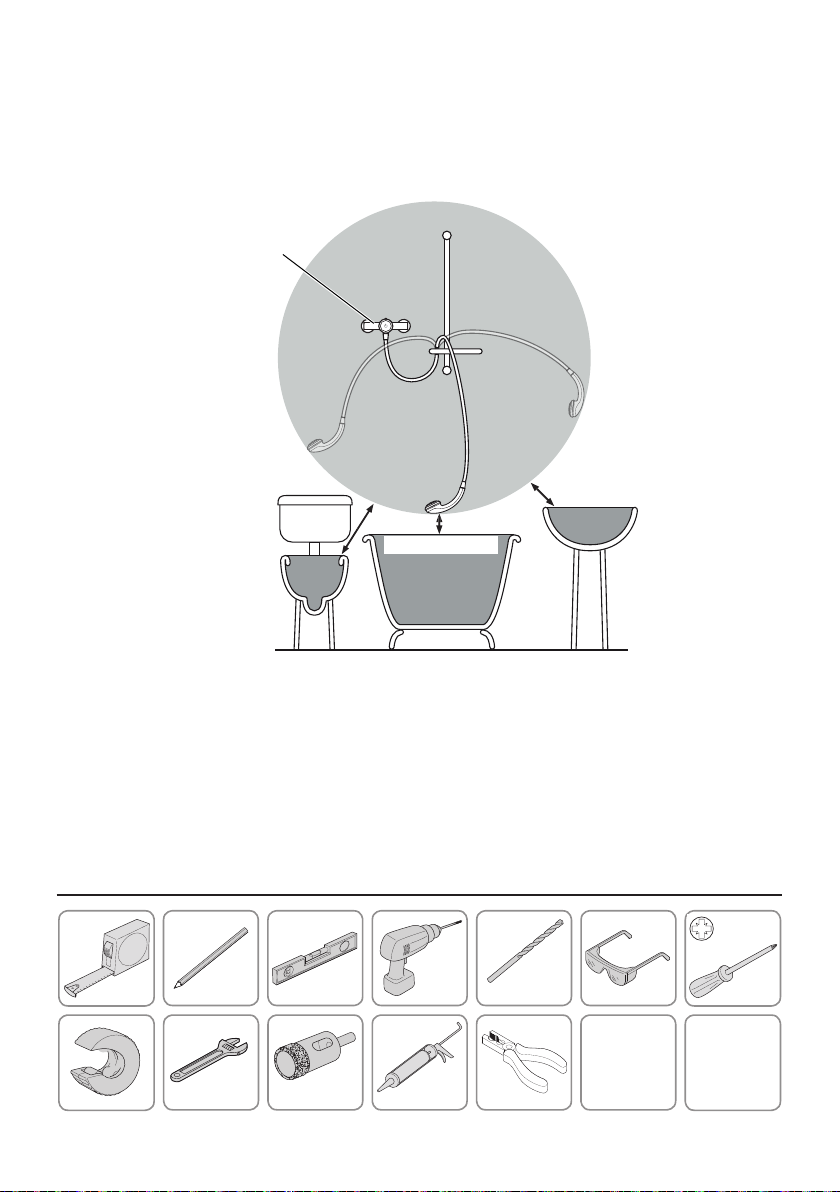
12. The position of the shower and shower ttings must provide a minimum air
gap of 25 mm between the showerhead and the spill over level of any bath,
shower tray or basin. There must be a minimum distance of 30 mm between
the showerhead and the spill over lever of any toilet, bidet or other appliance
with a Fluid Category 5 backow risk.
Shower
Unit
Zone of
Backflow
Risk
25 mm
Minimum
30 mm
Minimum
25 mm Minimum
Toilet or Bidet
FC5
Bath or Shower
Tray FC3
Hand Basin
FC3
Note ! There will be occasions when the hose retaining ring will not provide a suitable solution
for Fluid Category 3 installations. In these instances an outlet double checkvalve must be
tted, this will increase the required supply pressure typically by 10 kPa (0.1 bar). Double
checkvalves tted in the inlet supply to the appliance cause a pressure build up, which
aects the maximum static inlet pressure for the appliance and must not be tted. For Fluid
Category 5, double checkvalves are not suitable.
Tools Required
6.0 mm
16 - 19 mm
9
1285246-W2-D

Installation
Shower Positioning
The shower ttings should be positioned at a convenient height for all the family.
Position the ttings to spray across rather then towards the opening of the cubicle
and also away from the shower control. Avoid layouts where the shower hose will
be sharply kinked. This may reduce the life of the hose.
To enable sufficient
clearance the valve must
be a minimum 1.1 m
from the ceiling.
Agile ERD+
Offset Valve
to suit
Critical! The installation area must be carefully prepared and all tiles cut or
drilled accurately for a successful installation.
Note: This product DOES NOT allow for reversed inlets and will deliver dangerously
unstable temperatures if tted incorrectly. If the tile cutting area exceeds the
boundaries listed (step 6) below, the wall plate may not conceal drilled holes.
1285246-W2-D
10
 Loading...