

Mira Agile S B97C, Agile S Eco B97C, Agile Store EV+ B97D, Agile EV+ B97C, Agile ERD+ B97D Installation Manual
...Page 1
Mira Agile S Eco, Mira Agile S, Mira Agile ERD+
Mira Agile Sense ERD+, Mira Agile Store EV+, Mira Agile EV+
Installation and User Guide
These instructions must be left with the user
1
For SPARES,
ADVICE or REPAIRS
please call us free
on 0800 001 4040
(UK only)
1285246-W2-D
Page 2
Introduction
Thank you for choosing a Mira shower. To enjoy the full potential of your new shower,
please take time to read this guide thoroughly, and keep it handy for future reference.
Products manufactured by Kohler Mira Ltd are designed to be safe, provided that they are
installed, used and maintained in good working order, in accordance with our instructions
and recommendations.
Follow all warnings, cautions and instructions contained in this guide, and on, or inside the
shower. This guide is also available in digital format from our website or by contacting our
customer services department.
This product should not be disposed of with your general household waste. When this product
has reached the end of its serviceable life please take it to a recognised facility such as your
local civic amenity site for recycling. Your local authority or retailer will be able to advise you
of your nearest recycling facility.
Type 2 Valves
This product has been certied as a Type 2 valve. It also complies with the Water Supply
(water ttings) regulations 1999. For further information on Type 2 Valves, refer to the TMV2
Requirements Manual (this is available to view or download from our website www.
mirashowers.com).
The approved designation for this product is listed in the table below.
Mira Mixer Showers covered by this guide:
Product
Mira Agile S
Mira Agile S Eco
Mira Agile EV+
Mira Agile ERD+
Mira Agile Sense ERD+
Mira Agile Store EV+
Model
Number
B97C Chrome HP-S, HP-SE, LP-S
B97D Chrome HP-S, HP-SE, LP-S
Colour Type 2 Designation
Guarantee
This product has been designed for domestic use only, Mira Showers guarantee this product
against any defect in materials or workmanship for a period of ve years from the date of
purchase (shower ttings for one year).
Failure to follow the instructions provided with the shower will invalidate the guarantee
For terms and conditions, refer to the back cover of this guide.
Recommended Usage
Recommended Usage
Domestic
Heavy Commercial
1285246-W2-D
Light Commercial
Healthcare
2
Page 3
Design Registration & Patents
Design Registration:
001312649-0001 to 001312649-0022
Patents:
GB 2 422 886, 2 491 044, 2 500 948, 2 544 770
Euro: 1 672 257, 2 710 194, DE, FR, GB, IT, NL, SE
USA: 8 167 215, 8 517 282
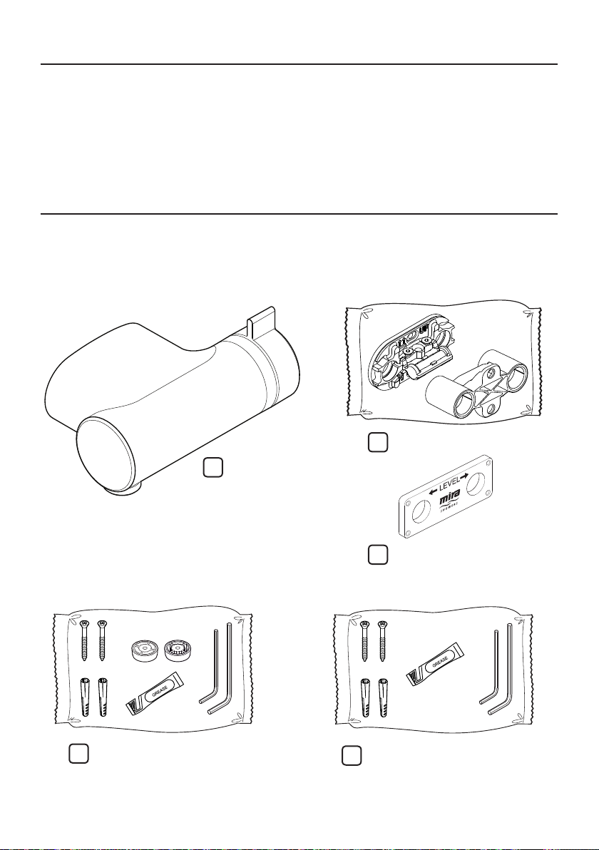
Pack Contents
Agile S
Agile S Eco
Agile EV+
1 x Wallplate Pack
1 x Shower Unit
Agile S & Agile EV+ Agile S Eco
1 x Component Pack
(2 x Screws, 2 x Wall Plugs, 2 x Flow Reg,
2 x Hex Key, 1 x Grease Sachet)
3
1 x Component Pack
(2 x Screws, 2 x Wall Plugs, 2 x Hex Key,
1 x Grease Sachet)
1 x First Fix Pipe Guide
1285246-W2-D
Page 4
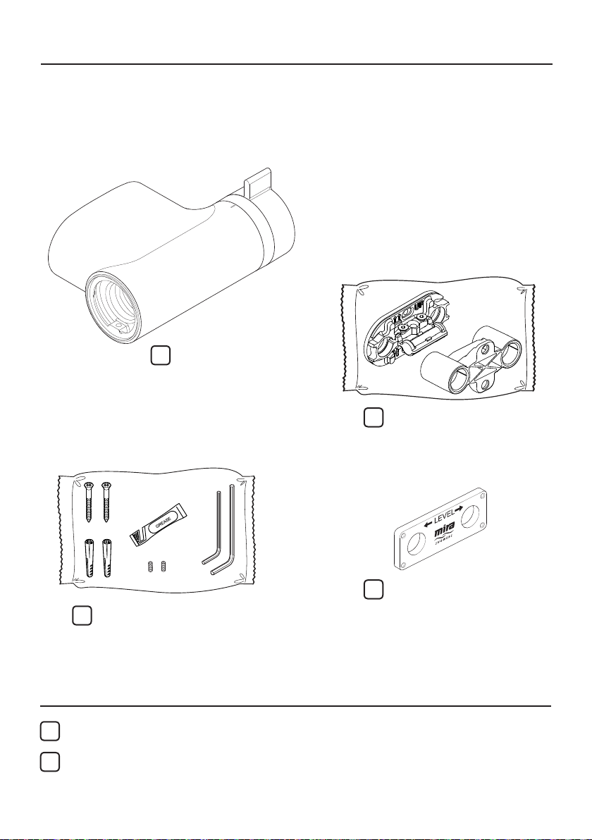
Pack Contents
Agile ERD+
Agile Sense ERD+
Agile Store EV+
1 x Shower Unit
1 x Wallplate Pack
1 x Component Pack
(2 x Screws, 2 x Wall Plugs, 2 x Hex Key,
1 x Grease Sachet, 2 x Grubscrew - 1 as
a spare)
Documents
1 x Installation & User Guide
1 x Guarantee Card
1285246-W2-D
1 x First Fix Pipe Guide
4
Page 5

Important Safety Information
WARNING ! This shower can deliver scalding temperatures. For
continued safe operation, follow all instructions, warnings and
cautions contained in this guide and on or inside the shower.
Periodic maintenance may be required to keep the product in
good working order.
The function of a thermostatic mixing valve is to deliver water
consistently at a safe temperature. In keeping with every other
mechanism, it cannot be considered as functionally infallible and
as such, cannot totally replace a supervisor’s vigilance where that
is necessary. Provided it is installed, commissioned, operated and
maintained within manufacturers recommendations, the risk of
failure, if not eliminated, is reduced to the minimum achievable.
PLEASE OBSERVE THE FOLLOWING TO REDUCE THE RISK
OF INJURY:
INSTALLING THE SHOWER
1. I nstallation of the shower must be carried out in accordance with
these instructions by qualied, competent personnel. Read all
instructions before installing the shower.
2 . DO NOT install the shower where it may be exposed to freezing
conditions. Ensure that any pipework that could become frozen is
properly insulated.
3 . DO NOT perform any unspecied modications to the shower
or its accessories. When servicing only use genuine Kohler Mira
replacement parts.
4 . If the shower is dismantled during installation or servicing then, upon
completion, an inspection must be made to ensure all connections
are tight and that there are no leaks.
USING THE SHOWER
5 . The shower must be operated and maintained in accordance with
the requirements of this guide. Make sure you fully understand how
to operate the shower before use, read all instructions and retain
this guide for future reference.
5
1285246-W2-D
Page 6

6. DO NOT switch the shower on if there is a possibility that the water
in the shower unit or ttings is frozen.
7 . The shower can be used by children aged from 8 years and above
and persons with reduced physical, sensory or mental capabilities
or lack of experience and knowledge if they have been given
supervision or instruction concerning use of the appliance in a safe
way and understand the hazards involved. Children must not be
allowed to play with the shower.
8 . Anyone who may have diculty understanding or operating the
controls of any shower should be attended whilst showering.
Particular consideration should be given to the young, the elderly,
the inrm or anyone inexperienced in the correct operation of the
controls.
9. DO NOT allow children to clean or perform any user maintenance
to the shower unit without supervision.
10. Always check the water temperature is safe before entering the
shower.
1 1 . DO NOT adjust the temperature control rapidly while using the
shower.
12. Use caution when altering the water temperature while in use,
always check the temperature before continuing to shower.
13. DO NOT switch the shower o and back on while standing in the
water ow.
14. DO NOT t any form of outlet ow control. Only Mira recommended
outlet ttings should be used.
1 5 . The showerhead must be descaled regularly. Any blockage of the
showerhead or hose may aect showering performance.
1 6 . The water supplies to this product must be isolated if the product is
not to be used for a long period of time. If the product or pipework
is at risk of freezing during this period they should also be drained
of water.
1 7 . When this product has reached the end of its serviceable life, it
should be disposed of in a safe manner, in accordance with current
local authority recycling, or waste disposal policy.
1285246-W2-D
6
Page 7

Specications
For Type 2 Valves, the supply conditions specied in the TMV2 Requirements Manual take
precedence over the operating parameters which follow.
Pressures
• Max Static Pressure: 10 Bar.
• Max Maintained Pressure: 5 Bar.
• Min Maintained Pressure (Gravity System): 0.1 Bar (0.5 Bar for models with Eco
Showerhead). (0.1 bar = 1 Metre head from cold tank base to showerhead outlet).
Note: For gravity fed or other low pressure systems (0.5 bar or below) do not t the outlet
ow regulator (where applicable).
• For optimum performance supplies should be nominally equal.
Temperatures
• Factory Pre-set (Blend) Shower: 43° C.
• Optimum Thermostatic Control Range: 35° C to 45° C (achieved with supplies of 15° C
cold, 65° C hot and nominally equal pressures).
• Recommended Hot Supply: 60° C to 65° C Note: The mixing valve can operate at higher
temperatures for short periods without damage, however this could detrimentally aect
thermostatic performance. For safety and performance reasons it is recommended that
the maximum hot water temperature is limited to 65° C.
• Cold Water Range: up to 25° C.
• Minimum Recommended Dierential between Hot Supply and Outlet Temperature: 12° C.
Thermostatic Shut-down
• For safety and comfort the thermostat will shut o the mixing valve within 2 Seconds if
either supply fails (achieved only if the blend temperature has a minimum dierential of
12° C from either supply temperature).
Connections
• Inlets: Mixing valve ONLY accepts 15mm OD copper pipe.
IMPORTANT This product is not suitable for use with any other pipe sizes
• Outlet: ½” BSP Flat Face
• Standard connections are:
• Hot - Left, Cold - Right
• Outlet - Bottom
WARNING! This product does not allow for reversed inlets and will deliver dangerously
unstable temperatures if tted incorrectly.
Suitable Plumbing Installations
Gravity Fed:
The thermostatic mixer must be fed from a cold water cistern (usually tted in the
loft space) and a hot water cylinder (usually tted in the airing cupboard) providing
nominally equal pressures.
Mains Pressurised Instantaneous Hot Water System (Combination Boiler):
The thermostatic mixer can be installed with systems of this type with balanced
pressures (Recommended Minimum Maintained Pressure: 1.0 Bar).
7
1285246-W2-D
Page 8

Unvented Mains Pressure System:
The thermostatic mixer can be installed with an unvented, stored hot water system.
Pumped System:
The thermostatic mixer can be installed with an inlet pump (twin impeller). The pump
must be installed in a suitable location and in accordance with its instructions.
Installation
General
1. Installation of the shower must be carried out in accordance with these instructions
by qualied, competent personnel.
2. The plumbing installation must comply with all national or local water regulations
and all relevant building regulations, or any particular regulation or practice
specied by the local water supply company.
3. Make sure all pressures and temperatures comply with the requirements of the
shower. See ‘Specications’. For Type 2 Valves, refer to supply conditions given
in the TMV2 Requirements Manual (this is available to view or download from
our website www.mirashowers.com).
4. Full bore/non restrictive servicing valves must be tted in a readily accessible
position adjacent to the shower to facilitate maintenance of the shower.
DO NOT use a valve with a loose washer plate (jumper) as this can lead to a
build up of static pressure.
5. DO NOT apply excessive force to plumbing connections; always provide
mechanical support when making plumbing connections. Any soldered joints
should be made before connecting the shower.
6. Pipework dead-legs should be kept to a minimum.
7. DO NOT install the shower unit in a position where access for maintenance is
restricted.
8. The shower must be tted to a waterproof, at and even wall surface. The two
screws and wall plugs supplied are suitable for most solid wall installations. Alternative
xing screws for panel structures are not supplied. Use both xing points to secure
the shower, be sure to use xings appropriate for the chosen wall structure.
9. When pipework enters the product from the rear through a hole in the wall,
provision must be made to prevent water ingress back into the wall structure.
10. Position the shower unit where the controls are at a convenient height for the
user. Position the showerhead so that the water sprays in line with the bath or
across the opening of a shower cubicle. The installation must not cause the
shower hose to be kinked during normal use.
11. The water supplies to this product should be isolated if the product is not to be
used for a long period of time. If the product or pipework is at risk of freezing
during this period they should also be drained of water.
1285246-W2-D
8
Page 9
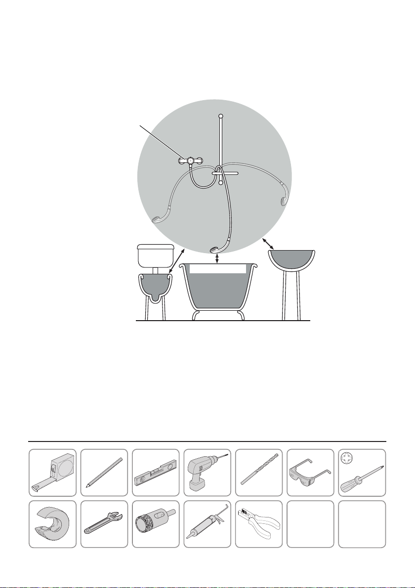
12. The position of the shower and shower ttings must provide a minimum air
gap of 25 mm between the showerhead and the spill over level of any bath,
shower tray or basin. There must be a minimum distance of 30 mm between
the showerhead and the spill over lever of any toilet, bidet or other appliance
with a Fluid Category 5 backow risk.
Shower
Unit
Zone of
Backflow
Risk
25 mm
Minimum
30 mm
Minimum
25 mm Minimum
Toilet or Bidet
FC5
Bath or Shower
Tray FC3
Hand Basin
FC3
Note ! There will be occasions when the hose retaining ring will not provide a suitable solution
for Fluid Category 3 installations. In these instances an outlet double checkvalve must be
tted, this will increase the required supply pressure typically by 10 kPa (0.1 bar). Double
checkvalves tted in the inlet supply to the appliance cause a pressure build up, which
aects the maximum static inlet pressure for the appliance and must not be tted. For Fluid
Category 5, double checkvalves are not suitable.
Tools Required
6.0 mm
16 - 19 mm
9
1285246-W2-D
Page 10

Installation
Shower Positioning
The shower ttings should be positioned at a convenient height for all the family.
Position the ttings to spray across rather then towards the opening of the cubicle
and also away from the shower control. Avoid layouts where the shower hose will
be sharply kinked. This may reduce the life of the hose.
To enable sufficient
clearance the valve must
be a minimum 1.1 m
from the ceiling.
Agile ERD+
Offset Valve
to suit
Critical! The installation area must be carefully prepared and all tiles cut or
drilled accurately for a successful installation.
Note: This product DOES NOT allow for reversed inlets and will deliver dangerously
unstable temperatures if tted incorrectly. If the tile cutting area exceeds the
boundaries listed (step 6) below, the wall plate may not conceal drilled holes.
1285246-W2-D
10
Page 11

1. Pipework must be at 50 mm centres, level
and perpendicular to the finished wall
surface (see g 1).
2. It is recommended that the pipework is
secure but not rigidly xed at this stage,
in case of further adjustment when the
retaining wallplate is tted.
3. Only use Ø15 mm copper pipe for
connection to the valve.
DO NOT use any other pipe sizes.
4. Ensure you have enough pipework through
the wall to allow it to be cut to the specied
length when wall is nished (refer to the
instruction on page 10).
5. The drill holes for the central tting of the
wallplate screws must be into brick, wooden
noggin or similar sound wall structure.
We recommend the sound wall structure
should extend to an area approximately 30
mm around the pipe centres (see g 2).
fig 1
Solid Wall Solid Wall
Pipe work installation viewed from above.
fig 2
30 mm
Make sure that
the pipework is
level
Pipe Centres
(50 mm)
30 mm
6. This product does not have a shroud,
accurate drilling of the tiles is essential to
allow the wallplate to prevent water ingress
and seal correctly
Hole size for tile drilling (g 3)
Min - 16 mm Max - 19 mm
11
fig 3
Ø 16 - 19 mm
1285246-W2-D
Page 12

7. For Stud Partition Walls
First Fix
Pipe Guide
Mark these two Holes
a. For stud partition wall installations make sure that a wooden noggin is in place
directly behind the nal valve position. The supplied First Fix Pipe Guide MUST
be used to mark the pipework centres, check that the pipe guide is level and
mark the pipework centres. DO NOT drill through the pipe guide.
Min: 19 mm Dia.
Max: 25 mm Dia.
50 mm
SIDE VIEW
TOP VIEW
b. Make sure the holes drilled through the noggin are square and level to the
mounting surface.
150 mm
150 mm
Pipe Clip
c. Plumb supplies using 15 mm copper pipework, make sure a minimum 150
mm of pipe extends from the front surface of the noggin. We recommend the
use of a pipe clip to secure the pipework within the wall, this MUST be placed
a minimum of 150 mm from the elbow joint.
1285246-W2-D
12
Page 13

1
5
m
m
LEVEL
LEVEL
* Pipework that is not level will make final assembly of
the valve very difficult
d. Once the pipework is in place, slide the First Fix Pipe Guide over the protruding
pipework.
Important! At this stage re-check the pipework is square and level*.
Mark and drill the pipe guide xing holes then attach directly to the noggin.
This can remain within the wall.
1
IMPORTANT !
Use 15 mm
copper pipe to
Pipe
Shroud
valve
Cold
Secured
Pipework
Hot
Install the pipework for stud partition or solid
wall, making sure they are level, square
and secure. When tiling the wall t the Pipe
Shroud over the pipe stubs. This will prevent
damage to the to the pipe surface from tiling
and grout etc and assist with the correct pipe
centres and alignment.
2
Min 18 mm to Max
28 mm from finished
wall surface
Tiles
Plasterboard
Hacksaw Pipe Slice
Remove the pipe shroud and trim the pipe
stubs to 23 mm +/-5 mm from the wall
surface DO NOT use a hacksaw as the
sharp edges may damage the seals in the
mixer valve. Note: De-burr the pipework if
necessary.
13
1285246-W2-D
1
5
m
m
Page 14

3
Drill holes
here
4
Pipe Shroud
Seal the
pipework where
it comes through
the wall
6 mm
Wall
Plug
Fit the Pipe Shroud over the pipe stubs. Use
the two holes in the pipe shroud as a template
and drill through them into the nished wall
surface. Drill through the 2x holes in the
shroud.
5
Wallplate
Fit the wallplate over the pipes ensuring
they do not push back into the wall and are
within the cut length tolerance (Min 18 mm
to Max 28 mm).
For solid wall installations, t the supplied
wall plugs (alternative xings can be used
- countersunk head only) to allow xing of
the wallplate.
6
Integrated
Spirit Level
Screw
Using the fixing screws provided, fix the
wallplate to the wall. Make sure that the
wallplate is level.
1285246-W2-D
14
Page 15

7
Screw
8
Pipe
Retaining
Screws
Pipe
Shroud
Integrated
Spirit Level
Ensure the pipes do not
push back into the wall.
Loosen the screws and remove the spirit
level and ret the pipe shroud to ensure the
pipes are aligned. Make sure the pipes do
not push back into the wall.
9
Retaining
Screw
Retaining
Screw
Hex Key
To prevent the possibility of property water
damage the screws MUST be tightened
YOU MUST FULLY TIGHTEN the pipe
retaining screws to clamp the pipes. Failure
to do so may result in water damage to your
property. Remove the pipe shroud.
Note: Only suitable for 15 mm pipe.
Retaining
Screw
Backplate
Remove the two external retaining screws.
Use a suitable pair of pliers to remove the backplate from the valve, holding where shown.
Remove the retaining screw from the backplate.
15
1285246-W2-D
Page 16

10
Retaining
Screw
To prevent the possibility of property
damage / personal injury the retaining
screw MUST be tightened.
DO NOT USE POWER TOOLS TO TIGHTEN
THE RETAINING SCREW
Grease the pipes and push the backplate fully
home onto the wallplate and pipes, taking
care not to damage the seals. Fit and tighten
the retaining screw with the hex key. Tighten
securely.
Orientation markers
always on top
Backplate
11
Flush the water supplies thoroughly
before connecting the shower unit.
In retrofit installations (where you are
replacing an old valve), remove and discard
the old lters.
12
Retaining
Screw
DO NOT USE POWER TOOLS TO TIGHTEN THE RETAINING SCREW
Push the valve over the backplate. Tighten the valve body retaining screws with the hexagonal
wrench. Tighten securely.
1285246-W2-D
Agile ERD+ / Sense ERD+ / Store EV+Agile S / S Eco / EV+
Retaining
Screw
16
Page 17

13
Turn on the water supplies and check for leaks. Refer to separate guide for instructions on
how to t the shower ttings. Note: The shower must be commissioned before rst use, see
section ‘Commissioning’ and ‘Information on Flow Regulators’.
17
1285246-W2-D
Page 18

14
Information on Flow Regulators
Shower Spray
Handset*
Washer
Note: For the S valves, fit
Hose
*Subject to the tting’s ability to accept the ow regulator.
the 12 l/min flow regulator
or 6 l/min flow regulator
into the handset as shown.
Note: For the ERD or Store products the
12 l/min flow regulator is pre fitted. For low
pressure systems, if more flow is required,
remove the flow regulator as shown.
Fit One Flow Regulator Per Outlet!
We highly recommend the tting of a ow regulator for optimum temperature control and
showering experience.
For maintained (running) water pressure greater than 0.5 bar, installing a ow regulator can
help to reduce:
• Excessive shower force
• Noise due to high or unequal water pressure
• Unstable supply temperature
• Cooler outlet temperatures due to the colder seasons
12 L/min (red) to reduce excessive shower force and stabilise temperatures.
6 L/min (black) for eco water conservation while showering.
Note: In some circumstances such as when the incoming cold water temperature supply is
very low to a combination boiler a 9 l/min ow regulator may be required to improve the hot
water performance. Contact Mira Customer Service.
Note: The 6 l/min ow regulator may aect the performance of some combination boilers
while the shower is running. Check with the boiler’s manufacturer before tting.
DO NOT t a ow regulator if the maintained (running) water pressure is less than 0.5 bar or
the shower force is too low.
1285246-W2-D
18
Page 19

Commissioning
Before using the shower, the maximum temperature must be checked to make sure that it is
at a safe level. It has been preset to a safe showering temperature under ideal conditions at
the factory, appropriate for most systems. However, site conditions and personal preference
may make it necessary to reset this temperature.
Note: Make sure that the hot water temperature is at least 55° C and that there is sucient
supply.
Make sure that all users are familiar with the operation of the shower. This guide is the
property of the homeowner.
Note: For Type 2 installations the maximum temperature is determined by application, refer
to the TMV2 Requirements Manual.
If you experience any diculty with the operation of your new shower, then please refer to
“Fault Diagnosis”, before contacting our customer services department.
Flow and Temperature Check
=
1. Turn the shower on and check the temperature adjustment operates correctly. (Allow a
few seconds for any temperature adjustment to take eect.)
2. Turn to maximum temperature (full hot) and allow the temperature and ow to
stabilise.
3. Turn the shower o.
Maximum Temperature Adjustment
Pull the control lever from the body then
remove the retaining screw with a 2.5 mm
hexagonal key.
21
Pull the stop assembly from the body.
19
1285246-W2-D
Page 20

3
O
F
F
Red Stopper
Handle Drive
Lift and adjust the position of the red stopper on back of the handle drive.
Each serration will adjust the temperature approximately 1° C
+ = Warmer
-
= Cooler
54
WarmerCooler
Ensuring correct orientation, “OFF” at
the top, ret the stop assembly and the
retaining screw to the body. Make sure the
stop assembly operates correctly and the
temperature is at the desired level.
1285246-W2-D
O
F
F
Turn the shower o again. Ret the control
lever.
20
Page 21

Operation
Please read “Important Safety Information” of this guide before using the shower for the
rst time.
Single Control mixers use a single sequential control for on / o and temperature
1
control.
The control operates clockwise in the
following sequence:
• O
• Cold
• Hot (Maximum Preset Temperature)
32
Always check the water temperature before
entering shower. The maximum preset
temperature (full hot) position can be
adjusted, see section ‘Commissioning’.
Turn the lever anti-clockwise to stop the
Shower.
Allow a few seconds for any temperature
adjustment to take eect.
Allow temperature to stabilise before making
a new adjustment.
54
Residual water may drain for a few minutes.
21
1285246-W2-D
Page 22

User Maintenance
O
F
F
WARNING! PLEASE OBSERVE THE FOLLOWING TO REDUCE
THE RISK OF INJURY OR PRODUCT DAMAGE:
■ DO NOT allow children to clean or perform any user maintenance
to the shower unit without supervision.
■ If the shower is not to be used for a long period, the water
supply to the shower unit should be isolated. If the shower unit
or pipework is at risk of freezing during this period, a qualied,
competent person should drain them of water.
Filter Cleaning
1
Isolate the water supplies and turn the
shower on to relieve the water pressure.
Turn the shower o.
3 4
Caution! Take care
not to damage the
chrome surfaces.
Stop
Assembly
Pull the control lever from the body then
remove the retaining screw with a 2.5 mm
hex key.
2
O
F
F
Pull the stop assembly from the body, then
unscrew and remove the large brass nut
from the body.
1285246-W2-D
Ensuring correct orientation, “OFF” at
the top, ret the stop assembly and the
retaining screw to the body.
22
Page 23

5
6
Grip the stop assembly and withdraw the
cartridge from the body.
Rinse the cartridge in clean warm water,
removing any dirt or debris.
7
END VIEW
Reassemble the valve in reverse order. Restore the water supplies and check for leaks.
Note: Make sure that the cartridge locates correctly.
Cleaning
Many household cleaners contain abrasives and chemical substances, and should not be used
for cleaning plated or plastic ttings. These nishes should be cleaned with a mild washing
up detergent or soap solution, and then wiped dry using a soft cloth.
Important! The showerhead must be descaled regularly. Keeping the shower spray clean
and free from limescale will ensure that your shower continues to give the best performance.
In-service Tests
The principal means for determining the continuing satisfactory performance of the shower
unit is the in-service test, refer to the TMV2 Requirements Manual.
Frequency of In-service Tests - Commercial (non-domestic installations)
Check for correct blend setting every 6 months.
23
1285246-W2-D
Page 24

Fault Diagnosis
Only use genuine Kohler Mira replacement parts.
If you require a Mira trained service engineer or agent, please see “Customer Service” on
the back cover of this guide.
Symptom Cause Recommended Action
Only hot or cold water
from the shower.
The shower temperature is
either too hot or too cold.
Fluctuating or reduced
flow rate.
Water leaking from the
shower head.
Movement of valve on the
wall.
Water inlets are reversed
(hot supply to cold supply).
No hot or cold water
reaching the shower unit.
Hose, shower head or filter
blocked.
The inlet pressures are
insufficient or unbalanced.
Air lock or partial blockage
in the pipework.
Flow regulator fitted
incorrectly.
Low flow causing
combination boiler to cycle.
Normal for a short period
after shut off.
The inlet pressures exceed
the requirements for the
shower unit.
Damage to the shower unit
cartridge.
Pressure spike in water
system.
Installation error, supply pipework
requires rework.
Check there is an adequate supply of
hot water. See ‘Specifications’.
Check the filters for any blockage refer
to section ‘User Maintenance’.
Installation conditions outside
operating parameters, refer to
sections: ‘Specification’ and
‘Commissioning’.
If the temperature is too cold and
you have a combination type boiler
it may not be producing sufficiently
hot water at desired flow rate (refer
to ‘Specification’). Make sure flow
regulator is fitted. For more information,
See ‘Information on Flow Regulators’
or contact Customer Service.
Remove and clean. Check hose
and replace if necessary. Check the
filters for any blockage. See ‘User
Maintenance’.
See ‘Specifications’.
Flush inlet pipes.
See Fittings Installation and User
Guide.
Incorrect flow reg fitted, blocked
showerhead, hose or filters.
See ‘Specifications’.
See ‘Specifications’.
Renew the cartridge.
Tighten the retaining screw.
1285246-W2-D
24
Page 25

Spare Parts
Agile S
Agile S Eco
Agile EV+
A
1736.980
Backplate
1736.706
Outlet Nipple
A
1736.990
Pipe Guide
1736.950
Cartridge
Assembly
1736.984
Headnut
A
1736.949
Control
Assembly
1736.962
Wall Plate
Assembly
1736.951
Component
Pack
1736.986 Screw Pack - A
25
1285246-W2-D
Page 26

Spare Parts
Agile ERD+
Agile Sense ERD+
Agile Store EV+
A
1736.980
Backplate
A
Pipe Guide
1736.990
1736.950
Cartridge
Assembly
1736.984
Headnut
A
1736.949
Control
Assembly
1736.962
Wall Plate
Assembly
1736.986 Screw Pack - A
1285246-W2-D
1928.049
Component
Pack
26
Page 27

Notes
27
1285246-W2-D
Page 28

Customer Service
Guarantee
Your product has the bene t of our manufacture's
guarantee which starts from date of purchase. This
guarantee only applies in the United Kingdom and
Republic of Ireland. To activate this guarantee, please
return your completed registration card, visit our
website or free phone 0800 5978551 within 30 days
of purchase (UK only).
Within the guarantee period we will resolve defects in
materials or workmanship, free of charge, by repairing
or replacing parts or product as we may choose.
This guarantee is in addition to your statutory
rights and is subject to the following conditions :
● The guarantee applies solely to the original
installation under normal use and to the original
purchaser only. The product must be installed and
maintained in accordance with the instructions
given in this guide.
● Servicing must only be undertaken by us or our
appointed representative.
Note! If a service visit is required the product must
be fully installed and connected to services.
● Repair under this guarantee does not extend
the original expiry date. The guarantee on any
replacement parts or product ends at the original
expiry date.
● For shower ttings or consumable items we
reserve the right to supply replacement parts only.
The guarantee does not cover:
● Call out charges for non product faults (such as
damage or performance issues arising from
incorrect installation, improper use, inappropriate
cleaning, lack of maintenance, build up of
limescale, frost damage, chemical attack,
corrosion, system debris or blocked lters) or
where no fault has been found with the product.
● Water or electrical supply, waste and isolation
issues.
● Compensation for loss of use of the product or
consequential or indirect loss of any kind.
● Damage or defects caused if the product is
repaired or modi ed by persons not authorised by
us or our appointed representative.
● Routine maintenance or replacement parts to
repaired or modi ed by persons not authorised by
comply with the requirements of the TMV2 or
repaired or modi ed by persons not authorised by
TMV3 healthcare schemes
● Accidental or wilful damage.
● Products purchased ex-showroom display.
What to do if something goes wrong
If your product does not work correctly refer to this
manual for fault diagnosis and check that it is installed
and commissioned in accordance with our instructions.
If this does not resolve the issue, contact us for help
and advice.
Helpdesk Service
Contact our Customer Services Team for
product advice, to purchase spare parts or
accessories or to set up service visit. You can contact
us via phone or e-mail - contact details below.
Please provide your model name, power rating (if
applicable) and date of purchase.
Mira Showers Website
(www.mirashowers.co.uk)
Visit our website to register your guarantee,
download user guides, diagnose faults, purchase
our full range of accessories and popular spares, or
request a service visit.
Spares and Accessories
We hold the largest stocks of genuine Mira
spares and accessories.Contact us for a
price or visit our website to purchase items from our
accessory range and popular spares. (Only available
in the United Kingdom )
Service/Repairs
No one knows our products better than our
nationwide team of Service Technicians. We
can carry out service or repair work to your product
both during and after the guarantee period. (Only
available in the United Kingdom and Republic of
Ireland) Ask about our xed price service repairs.
To Contact Us: UK
0800 001 4040
Fax: 01242 282595
Email – Visit
www.mirashowers.co.uk/contactus
By Post: Mira Customer Services Dept, Cromwell
Road, Cheltenham, Gloucestershire GL52 5EP
To Contact Us: Eire Only
01 531 9337
E-mail:
CustomerServiceEire@mirashowers.com
Mira is a registered trade mark of
Kohler Mira Limited.
The company reserves the right to alter
product specifi cations without notice.
1285246-W2-D
28
14648
© Kohler Mira Limited, February 2019
Page 29

Product Datasheet
Mira Agile S EV
Agile S Eco EV
& Agile EV+
Mixer Shower
A neat, contemporary
shower which delivers
maximum showering
performance.
Product Information
Description Colour Product No.
Mira Agile S EV Chrome 1.17 3 6 . 4 0 1
Mira Agile S Eco EV Chrome 1.17 3 6 . 4 0 0
Mira Agile EV+ Chrome 1.19 28. 0 07
Features & Benets
Temperature control
Thermostatic temperature control makes showering
safer for all the family
Easy to t
Spanner-free installation
Pipe and tiling templates included
Patented in-valve push t connection
Pipe centres 50 mm apart
Adjustable slide bar xings
Easy to service
Replaceable cartridge
For your customer
Single control for ow and temperature
Mira Magni-o™ technology delivers up to 3x more ow,
even at low pressure
90 mm showerhead with rub-clean nozzles for a greater
showering ex perience (Agile EV+ has 4 spray 110 mm showerhead)
www.mirashowers.co.uk/expert
Page 30

Product Specication
Technical Details
Temperature control
Control type: Thermostatic temperature control
Installation
Water entry points: rear only
Inlet connections: 15 mm copper pipe
Outlet connections: ½” BSP Male Flat Face
Reversed inlets supported: No = hot left, cold right only
Supply Conditions (hot and cold)
Cold water range: 1°C to 25°C
Hot water range: 55°C-65°C (recommended for optimum performance)
Minimum maintained pressure: 0.1 bar (1 metre head)
Maximum maintained pressure: 5.0 bar (50 metre head)
Maximum static pressure: 10.0 bar (100 metre head)
For optimum performance supplies should be nominally equal.
Performance
Flow rate (at handset): Agile S EV, 10 l/min at 0.5 bar;
Agile S Eco EV, 6 l/min at 0.5 bar; Agile EV+, 11 l/min at 0.5 bar
Temperature stability: ± 2°C
Safety Features
Automatic shutdown: Shutdown within 2 secs should either supply fail
Factory set to safe max temp: Factory set to 43°C
Approvals
KIWA UK approved product
WRAS approved (Water Regulations Advisory Scheme)
Buildcert TMV2 Approved
Dimensions
80 mm
50 mm
50 mm
133 mm
45 mm
58 mm
61 mm
44 mm
83 mm
562 mm
310 mm
510 mm
www.mirashowers.co.uk/expert
Page 31

CUSTOMER SERVICE
Guarantee
Your product has the bene t of our manufacture's 1
year guarantee which starts from date of purchase.
This guarantee only applies in the United Kingdom
and Republic of Ireland. Within the guarantee period
we will resolve defects in materials or workmanship,
free of charge, by replacing parts or product as we
may choose.
This guarantee is in addition to your statutory
rights and is subject to the following conditions :
● The product must be installed and maintained
in accordance with the instructions given in this
user guide.
● Replacement under this guarantee does not
extend the original expiry date .
● The guarantee on any replacement parts or
product ends at the original expiry date.
The guarantee does not cover:
● Non product faults (such as damage or
performance issues arising from incorrect
installation, improper use, inappropriate cleaning,
lack of maintenance, build up of limescale, frost
damage, corrosion, chemical attack, system
debris or blocked lters) or where no fault has
been found with the product.
● Accidental or wilful damage.
● Compensation for loss of use of the product or
consequential or indirect loss of any kind.
● Damage or defects caused if the product is
repaired or modi ed by persons not authorised by
us or our appointed representative.
What to do if something goes wrong
If your product does not function correctly when you
rst use it, check that it is installed and commissioned
in accordance with the instructions in this manual. If
this does not resolve the issue, contact us for help
and advice.
Helpdesk Service
Our Customer Services Team is
comprehensively trained and can offer help
and advice, spare parts and accessories. We will
need you to have your model name or number and
date of purchase. Please provide your model name
and date of purchase.
Mira Showers Website
(www.mirashowers.co.uk)
From our website you can download
additional user guides, diagnose faults, purchase
our full range of accessories and popular spares and
refer to our FAQ's
Mira is a registered trade mark of
Kohler Mira Limited.
The company reserves the right to alter
product specifi cations without notice.
Spares and Accessories
We hold the largest stocks of genuine Mira
spares and accessories. Contact us for a
price or visit our website to purchase items from our
accessory range and popular spares. (Only available
in the United Kingdom )
To Contact Us: UK
0800 001 4040
Fax: 01242 282595
Email
www.mirashowers.co.uk/contactus
By Post:
Mira Customer Services Dept, Cromwell Road,
Cheltenham, Gloucestershire GL52 5EP
To Contact Us: Eire Only
01 531 9337
E-mail:
CustomerServiceEire@mirashowers.com
14648
MIRA AGILE & ADEPT
EV FITTINGS, AGILE
EV+, AGILE STORE EV+,
AGILE S ECO, AGILE S
Introduction
Thank you for purchasing a quality Mira product. To
enjoy the full potential of your new product, please
take time to read this guide thoroughly, having
done so, keep it handy for future reference.
Mira shower fittings are designed to give a
satisfactory shower over a range of pressures.
These ttings are suitable for pressures between
0.1 and 5.0 bar.
General
1. Make sure that the shower fittings are
installed by a competent installer.
2. Installations must comply with Water
Regulations (Bye-Laws, Scotland), and
any other Local Regulations and Building
Regulations in force at the time of
installation.
3. Before installation carefully inspect the new
xture for any signs of damage.
4. The shower ttings should be positioned
at a convenient height for all the family.
Position the ttings to spray across rather
then towards the opening of the cubicle
and also away from the shower control.
Avoid layouts where the shower hose will
be sharply kinked. This may reduce the life
of the hose.
5. A hose retaining ring is supplied to prevent
the handset from dropping below the spill
over level of the bath or shower, which
could lead to contamination from back-
siphonage. The supplied hose retaining
ring should meet the great majority of user
requirements for shower installations with
exible outlet ttings. However, there will
be occasions when the hose retaining ring
will not provide a suitable solution. In these
instances an outlet double check valve,
e.g. The Mira DCV-H, must be tted. The
inclusion of the Mira DCV-H will increase
the required supply pressure typically by
0.1 bar.
6. Do not t any form of ow control in the
outlet pipe work if the shower ttings are
installed in conjunction with a product that
requires the ttings to act as a vent (e.g.
an electric shower).
7. Special consideration should be given to
the xing arrangements when installing
onto a dry lined, stud partition, shower
cubicle or laminated panel wall structures.
Installers may wish to obtain alternative
proprietary cavity xings, or choose other
options, however, these methods of xing
are beyond the scope of this guide.
Cleaning
Many household cleaners contain abrasives and
chemical substances, and should not be used for
cleaning plated or plastic ttings.
These nishes should be cleaned with a mild
washing up detergent or soap solution, and then
wiped dry using a soft cloth.
Use your thumb or a soft cloth to wipe any
limescale from the soft nozzles and the front
surface of the handset spray plate.
Spare Parts
Spare part numbers are indicated in bold and are
available from authorised stockists or merchants
(locations on request) or direct from Mira
Customer Services, our contact details can be
found on the back cover of this guide.
1199921-W2-B © Kohler Mira Limited, October 2018
Page 32

Shower Hose
1736.738 (Metal)
1736.739 (Smooth)
1736.738 (Metal)
1736.739 (Smooth)
Flow
Regulator
Shower Hose
Shower Hose Outlet
1736.713
1736.726 (Eco)
*
'A'
Components 'A'
1703.194
'A' (x2)
Mounting Pack
Slide Bar
Support
Hose Retaining Ring
1703.199
pipes or
cables.
Caution!
Do not drill
into buried
Clamp Bracket
1703.203 (Chrome)
1740.369 (110 mm - Multi Mode)
Hose Seal (x2)
632.73
Screw Fixing
Hole
Slide Bar
Clamping
Screw
Showerhead
1703.351 (90 mm - Single Mode)
1736.729 (90 mm - Single Mode Eco)
1703.353 (90 mm - Multi Mode)
1736.728 (90 mm - Multi Mode Eco)
Slide Bar Support (x2)
(includes screws)
1703.201 (Chrome)
Slide Bar
1736.737
Mounting
Bracket
Slide Bar
Slide Bar Support
Tighten slide bar clamping
screw no more than 1/2 turn
M4 Screws 'A'
(x2)
Cap (x2)
1703.196
Note! Do not overtighten
the screws
*
12 L/min Flow Regulator location, for low pressure
installations this should be removed. For 'Eco'
variants a 6 L/min ow regulator is permanently
installed in the Showerhead
7. Install the slide bar assembly onto the
mounting brackets. Tighten the 2 x M4
screws with the supplied 3 mm hexagonal
key. Caution! Do not force assembly on
to the mounting brackets, re-align a slide
bar support if required.
damage.
6. Tighten the two slide bar clamping screws
no more than 1/2 turn to secure the slide
bar supports to the slide bar. Caution!
Overtightening these screws will cause
5. Remove the slide bar assembly carefully,
over the mounting brackets, then adjust
the slide bar vertically ensuring an equal
length of slide bar protrudes from the top
preventing any further movement between
the slide bar and slide bar supports.
and bottom mounting bracket.
bar supports. Fit the slide bar supports
4. Ensure the slide bar clamping screws
are ush with the inside edge of the slide
Shower Fittings Installation
3. Install the clamp bracket and the slide bar
mounting brackets are slotted to aid
supports (and the hose retaining ring if
supplied) onto the slide bar.
adjustment.
2. Install the wall plugs and mounting
brackets and secure with the screws.
Check vertical alignment. Note! The
moved to suit grout lines if required.
1. Mark the wall xing hole positions and
drill two holes 510 mm apart to suit the
wall xings. Note! Slide Bar ends can be
diverter to the mixer valve / outlet.
2. Tighten the outer grubscrew until it
the outlet into the end of the mixer valve.
bottoms out (2.5 mm hexagonal key), then
tighten a further 1/2 turn to secure the
Shower Hose Outlet
1. With the outlet thread facing down push
 Loading...