

Mira Advance Maintance Manual
11
11
1
5
6
4
7
3
8
2
9
1
Low Pressure
H
ig
h
M
e
d
iu
m
L
o
w
Stop
Te
m
p
e
ra
tu
r
e
S
e
rv
ic
e
5
6
4
7
3
8
2
9
1
1
Low Pressure
H
ig
h
M
e
d
iu
m
L
o
w
Stop
S
to
re
2
3
4
5
Te
m
p
e
r
a
tu
re
Flow
Flow
S
e
rv
ic
e
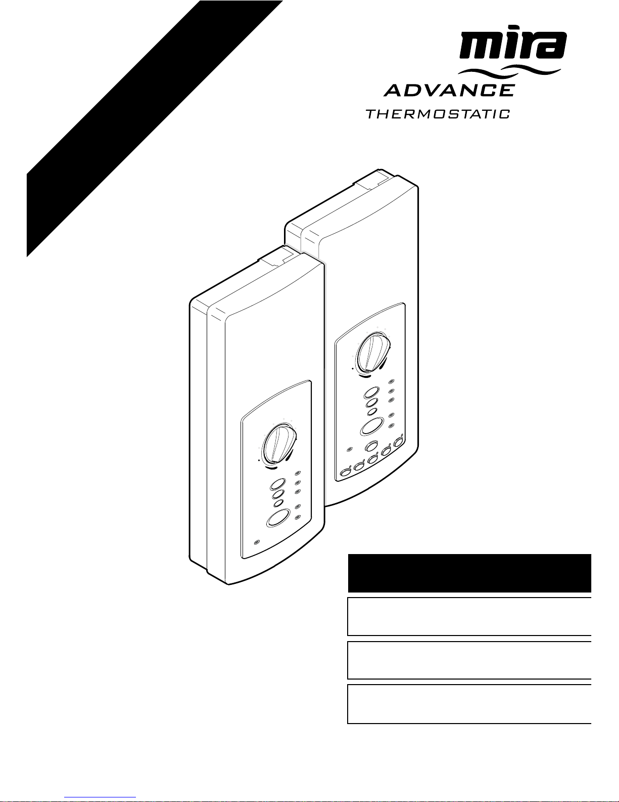
Maintenance Guide
Operation &B
Installation
ELECTRIC SHOWERS
Standard & MemoryStandard & Memory
Standard & MemoryStandard & Memory
Standard & Memory
models coveredmodels covered
models coveredmodels covered
models covered
THESE INSTRUCTIONS ARE TO BE LEFT WITH THE USERTHESE INSTRUCTIONS ARE TO BE LEFT WITH THE USER
THESE INSTRUCTIONS ARE TO BE LEFT WITH THE USERTHESE INSTRUCTIONS ARE TO BE LEFT WITH THE USER
THESE INSTRUCTIONS ARE TO BE LEFT WITH THE USER

22
22
2
ContentsContents
ContentsContents
Contents
PagePage
PagePage
Page
IntroductionIntroduction
IntroductionIntroduction
Introduction
..........................................................................................................................
..........................................................................................................................
.............................................................
33
33
3
Important Safety InformationImportant Safety Information
Important Safety InformationImportant Safety Information
Important Safety Information
............................................................................................
............................................................................................
..............................................
44
44
4
Pack Contents ChecklistPack Contents Checklist
Pack Contents ChecklistPack Contents Checklist
Pack Contents Checklist
..........................................................................................................
..........................................................................................................
.....................................................
77
77
7
DimensionsDimensions
DimensionsDimensions
Dimensions
..........................................................................................................................
..........................................................................................................................
.............................................................
88
88
8
Wiring DiagramWiring Diagram
Wiring DiagramWiring Diagram
Wiring Diagram
........................................................................................................................
........................................................................................................................
............................................................
1010
1010
10
SpecificationsSpecifications
SpecificationsSpecifications
Specifications
........................................................................................................................................
........................................................................................................................................
....................................................................
1111
1111
11
Installation RequirementsInstallation Requirements
Installation RequirementsInstallation Requirements
Installation Requirements
....................................................................................................
....................................................................................................
..................................................
1212
1212
12
InstallationInstallation
InstallationInstallation
Installation
........................................................................................................................
........................................................................................................................
............................................................
1616
1616
16
CommissioningCommissioning
CommissioningCommissioning
Commissioning
....................................................................................................................................
....................................................................................................................................
..................................................................
2121
2121
21
OperationOperation
OperationOperation
Operation
......................................................................................................................................................
......................................................................................................................................................
...........................................................................
2323
2323
23
Fault DiagnosisFault Diagnosis
Fault DiagnosisFault Diagnosis
Fault Diagnosis
....................................................................................................................................
....................................................................................................................................
..................................................................
2929
2929
29
MaintenanceMaintenance
MaintenanceMaintenance
Maintenance
............................................................................................................................................
............................................................................................................................................
......................................................................
3636
3636
36
Maximum Temperature SettingMaximum Temperature Setting
Maximum Temperature SettingMaximum Temperature Setting
Maximum Temperature Setting
....................................................................................
....................................................................................
..........................................
4242
4242
42
Spare PartsSpare Parts
Spare PartsSpare Parts
Spare Parts
................................................................................................................................................
................................................................................................................................................
........................................................................
4343
4343
43
Guarantee, Customer Care Policy, and How to contact usGuarantee, Customer Care Policy, and How to contact us
Guarantee, Customer Care Policy, and How to contact usGuarantee, Customer Care Policy, and How to contact us
Guarantee, Customer Care Policy, and How to contact us
..............................................................................................................................................
..............................................................................................................................................
.......................................................................
Back covBack cov
Back covBack cov
Back cov
erer
erer
er

33
33
3
Section
1
IntroductionIntroduction
IntroductionIntroduction
Introduction
Thank you for purchasing a quality Mira product. To exploit the full potential of your new
shower, please take time to read this guide thoroughly, having done so, keep it handy
for future reference.
The Mira Advance is a high performance electric shower, which provides thermostatic
temperature control. The Mira Advance compensates for pressure, temperature and
voltage changes to achieve a very accurate temperature whilst showering. Separate
push-button controls allow the user to select three independent flow settings. The Mira
Advance features as standard, a safe ‘maximum temperature setting’, but also has a
special feature which allows the shower temperature to be limited to 43°C.
A memory control version is available which allows the user to preset five choices of flow
level and temperature, which can be recalled on demand.
For healthcare or special need requirements, refer to "Maximum Temperature Setting".
Mira Advance covered by this guide:
Mira Advance (standard control)Mira Advance (standard control)
Mira Advance (standard control)Mira Advance (standard control)
Mira Advance (standard control) 8.7 kW 240 Volts, 8.0 kW 230 Volts
Mira Advance (standard control)Mira Advance (standard control)
Mira Advance (standard control)Mira Advance (standard control)
Mira Advance (standard control) 9.8 kW 240 Volts, 9.0 kW 230 Volts
Mira Advance (Mira Advance (
Mira Advance (Mira Advance (
Mira Advance (
memorymemory
memorymemory
memory
control) control)
control) control)
control) 8.7 kW 240 Volts, 8.0 kW 230 Volts
Mira Advance (Mira Advance (
Mira Advance (Mira Advance (
Mira Advance (
memorymemory
memorymemory
memory
control) control)
control) control)
control) 9.8 kW 240 Volts, 9.0 kW 230 Volts
If you experience any difficulty with the installation or operation of your new Mira
Advance, then please refer to
Fault DiagnosisFault Diagnosis
Fault DiagnosisFault Diagnosis
Fault Diagnosis, before contacting Caradon
Plumbing Solutions. Our telephone and fax numbers can be found on the back cover
of this guide.

44
44
4
Section
2
Important Safety InformationImportant Safety Information
Important Safety InformationImportant Safety Information
Important Safety Information
1.1.
1.1.
1.
WW
WW
W
arar
arar
ar
ning!ning!
ning!ning!
ning!
1.1.1.1.
1.1.1.1.
1.1. Products manufactured by us are safe and without risk provided they are
installed, used and maintained in good working order in accordance with our
instructions and recommendations.
1.2.1.2.
1.2.1.2.
1.2. THIS MIRA ADVANCE
MUSTMUST
MUSTMUST
MUST BE EARTHED.
1.3.1.3.
1.3.1.3.
1.3. In accordance with the current edition of ‘The Plugs and Sockets etc.
(Safety) Regulations in force at the time of installation, this Mira Advance is
intended to be permanently connected to the fixed electrical wiring of the
mains system.
1.4.1.4.
1.4.1.4.
1.4.
DO NOTDO NOT
DO NOTDO NOT
DO NOT twist the individual cable cores of the live and neutral conductors,
as this will prevent them from entering the terminal block.
1.5.1.5.
1.5.1.5.
1.5. Make sure that any pipework that could become frozen is properly
insulated.
1.6.1.6.
1.6.1.6.
1.6.
DO NOTDO NOT
DO NOTDO NOT
DO NOT operate this Mira Advance if it is frozen. Allow the Mira Advance to
thaw before using again. The shower unit must not be fitted where it may be
exposed to freezing conditions.
1.7.1.7.
1.7.1.7.
1.7. If water leaks from the pressure relief valve, maintenance will be required
before the Mira Advance can be safely used.
1.8.1.8.
1.8.1.8.
1.8.
DO NOT DO NOT
DO NOT DO NOT
DO NOT fit any form of outlet flow control as the outlet acts as a vent for
the tank body. Only Mira recommended outlet fittings should be used.
1.9.1.9.
1.9.1.9.
1.9. There are no user serviceable components beneath the cover of the Mira
Advance. Only a competent tradesperson should remove the cover.
1.10.1.10.
1.10.1.10.
1.10. If any of the following conditions occur, isolate the electricity and water
supplies and refer to
“To contact us”“To contact us”
“To contact us”“To contact us”
“To contact us”, on the back page of this guide.
1.10.1.1.10.1.
1.10.1.1.10.1.
1.10.1. If the cover is not correctly fitted and water has entered the Mira
Advance case.
1.10.2.1.10.2.
1.10.2.1.10.2.
1.10.2. If the case is damaged.
1.10.3.1.10.3.
1.10.3.1.10.3.
1.10.3. If the Mira Advance begins to make an odd noise, smell or smoke.
1.10.4.1.10.4.
1.10.4.1.10.4.
1.10.4. If the Mira Advance shows signs of a distinct change in performance,
indicating a need for maintenance.
1.10.5.1.10.5.
1.10.5.1.10.5.
1.10.5. If the Mira Advance is frozen.

55
55
5
1.11.1.11.
1.11.1.11.
1.11. Isolate the electrical and water supply before removing the cover.
1.12.1.12.
1.12.1.12.
1.12. Mains connections are exposed when the cover is removed.
1.13.1.13.
1.13.1.13.
1.13. Refer to the wiring diagram before making any electrical connections.
1.14.1.14.
1.14.1.14.
1.14. Ensure all electrical connections are tight, to prevent overheating.
2. Caution!2. Caution!
2. Caution!2. Caution!
2. Caution!
2.1.2.1.
2.1.2.1.
2.1.
Read all of these instructions and retain this guide for later use.Read all of these instructions and retain this guide for later use.
Read all of these instructions and retain this guide for later use.Read all of these instructions and retain this guide for later use.
Read all of these instructions and retain this guide for later use.
2.2.2.2.
2.2.2.2.
2.2. Pass on this guide in the event of change of ownership of the installation
site.
2.3.2.3.
2.3.2.3.
2.3. Follow all warnings, cautions and instructions contained in this guide, and
on or inside the Mira Advance.
2.4.2.4.
2.4.2.4.
2.4. The electrical installation must comply with the “Requirements for Electrical
Installations” commonly referred to as the IEE Wiring Regulations, or any
particular regulations and practices, specified by the local electricity supply
company in force at the time of installation. The installation should be
carried out by an electrician or contractor who is registered, or is a member
of, an association such as:
2.5.2.5.
2.5.2.5.
2.5. This is a high power unit; it is essential to contact your electricity supply
company to ensure that the electricity supply is adequate for the purpose.
2.6.2.6.
2.6.2.6.
2.6. The plumbing installation must comply with the requirements of UK Water
Regulations/Bylaws (Scotland), Building Regulations or any particular
regulations and practices, specified by the local water company or water
undertakers. The installation should be carried out by a plumber or
contractor who is registered, or is a member of, an association such as:
2.4.1.2.4.1.
2.4.1.2.4.1.
2.4.1. National Inspection Council for Electrical Installation and Contracting
(NICEIC), throughout the UK, Tel: 0171 582 7746.
2.4.2.2.4.2.
2.4.2.2.4.2.
2.4.2. The Electrical Contractors Association (ECA), England and Wales,
Tel: 0171 229 1266.
2.4.3.2.4.3.
2.4.3.2.4.3.
2.4.3. The Electrical Contractors Association of Scotland (ECAS),
Tel: 0131 445 5577.
2.6.1.2.6.1.
2.6.1.2.6.1.
2.6.1. Institute of Plumbing (IOP), throughout the UK, Tel: 01708 472791.
2.6.2.2.6.2.
2.6.2.2.6.2.
2.6.2. National Association of Plumbing, Heating and Mechanical Services
Contractors (NAPH & MSC), England and Wales, Tel: 01203 470626.
2.6.3.2.6.3.
2.6.3.2.6.3.
2.6.3. Scottish and Northern Ireland Plumbing Employers’ Federation (SNIPEF),
Scotland and Northern Ireland, Tel: 0131 225 2255.

66
66
6
2.7.2.7.
2.7.2.7.
2.7. Anyone who may have difficulty understanding or operating the controls of any
shower should be attended whilst showering. Particular consideration should be
given to the young, the elderly, the infirm, or anyone inexperienced in the correct
operation of the controls.
2.8.2.8.
2.8.2.8.
2.8. When this Mira Advance has reached the end of its serviceable life, it should be
disposed of in a safe manner, in accordance with current local authority
recycling, or waste disposal policy.
77
77
7
5
6
4
7
3
8
2
9
1
Low Pressure
H
ig
h
Medium
L
o
w
S
to
p
Tem
pera
ture
Service
5
6
4
7
3
8
2
9
1
1
Low Pressure
H
ig
h
Medium
L
o
w
S
to
p
Store
2
3
4
5
Tem
perature
F
lo
w
F
lo
w
Service
Section
3
PP
PP
P
acac
acac
ac
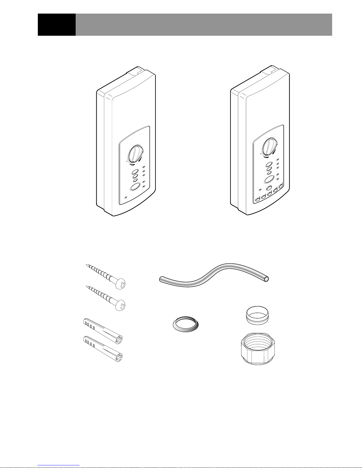
k Contents Check Contents Chec
k Contents Check Contents Chec
k Contents Chec
klistklist
klistklist
klist
or
¨ Tick the appropriate boxes to familiarize yourself with the part names and to confirm that
the parts are included.
ü
1 x Mira Advance ¨
1 x Olive ¨
2 x Wall Screws ¨
2. Documentation2. Documentation
2. Documentation2. Documentation
2. Documentation
1 x Installation, Operation and Maintenance Guide ¨
1 x Customer Support Brochure ¨
1 x Wall Plugs ¨
1 x Earth Sleeve ¨
1 x Compression Nut ¨
(for fitting to existing tap connector)
1 x Tap Connector Adaptor¨
88
88
8
5
6
4
7
3
8
2
9
1
H
ig
h
Medium
L
o
w
Stop
Temperature
5
6
4
7
3
8
2
9
1
L
o
w
P
re
s
s
u
re
H
ig
h
Medium
L
o
w
Stop
Temperature
S
e
rv
ic
e
L
o
w
P
re
s
s
u
re
Low
Pressure
1
2
3
4
5
Store
Flow
Flow
S
e
rv
ic
e
Service
Caradon Mira contact telephone and fax numbers.
4
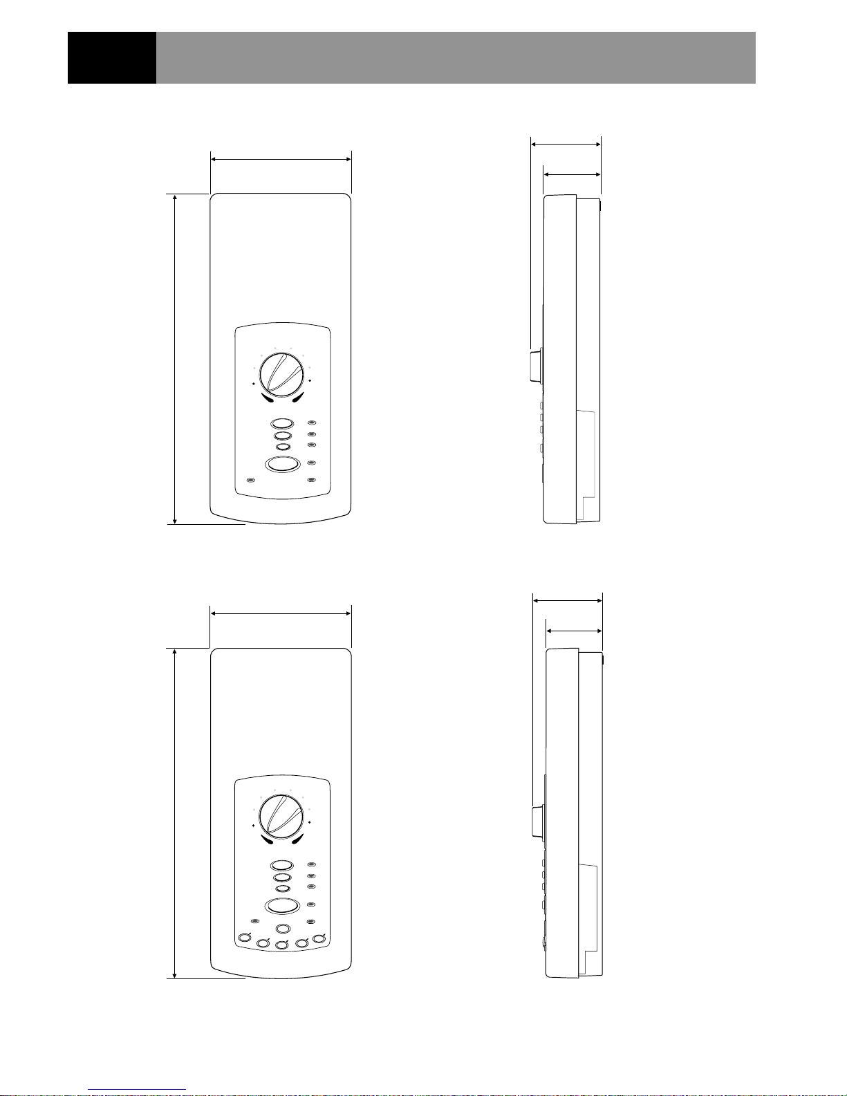
DimensionsDimensions
DimensionsDimensions
Dimensions
Section
168
395
395
1.1.
1.1.
1.
Mir Mir
Mir Mir
Mir
a Adva Adv
a Adva Adv
a Adv
anceance
anceance
ance
168
68
84.5
68
84.5
Standard Model
Memory Model
All dimensions are nominal and in millimetres.
99
99
9
L
N
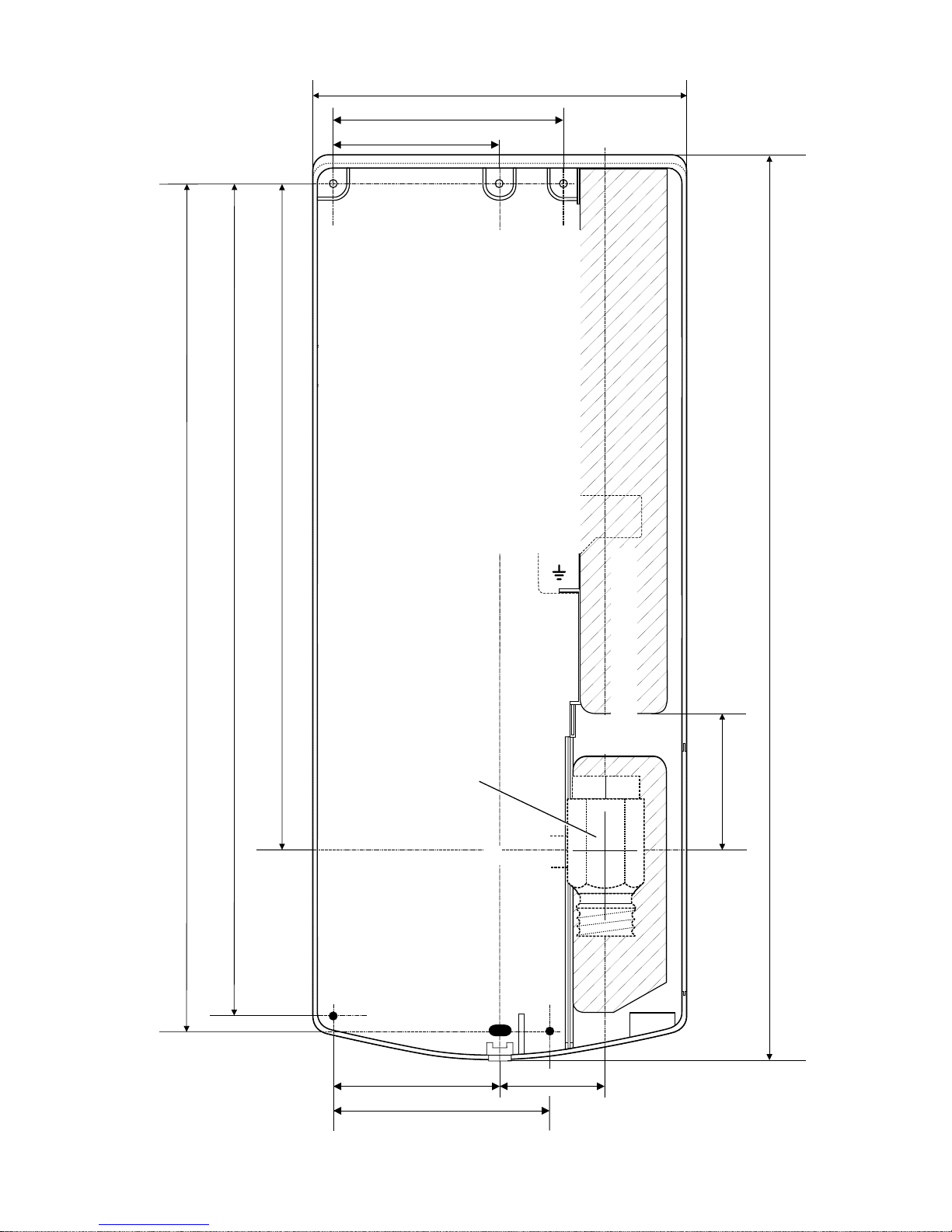
Important PointsImportant Points
Important PointsImportant Points
Important Points
11
11
1 The top and bottom of
the case walls have
thinned sections for ease
of removal to accept top
or bottom water inlet.
22
22
2 The hatched areas are
case cutouts to allow
cable and pipe access.
33
33
3 Ensure screw fixings do
not puncture buried
cables.
73
Mira Advance centre line
Inlet Connector
centre line
46.5
Supply pipe centre line
288
395
59
95
168
101
73
360
367
Inlet Connector
Assembly
(Bottom inlet
shown)
All dimensions are nominal and in millimetres.
2.2.
2.2.
2.
WW
WW
W
ater and Cabater and Cab
ater and Cabater and Cab
ater and Cab
le Entrle Entr
le Entrle Entr
le Entr
y Py P
y Py P
y P
ointsoints
ointsoints
oints
1010
1010
10
5
MirMir
MirMir
Mir
a Adva Adv
a Adva Adv
a Adv
ance ance
ance ance
ance
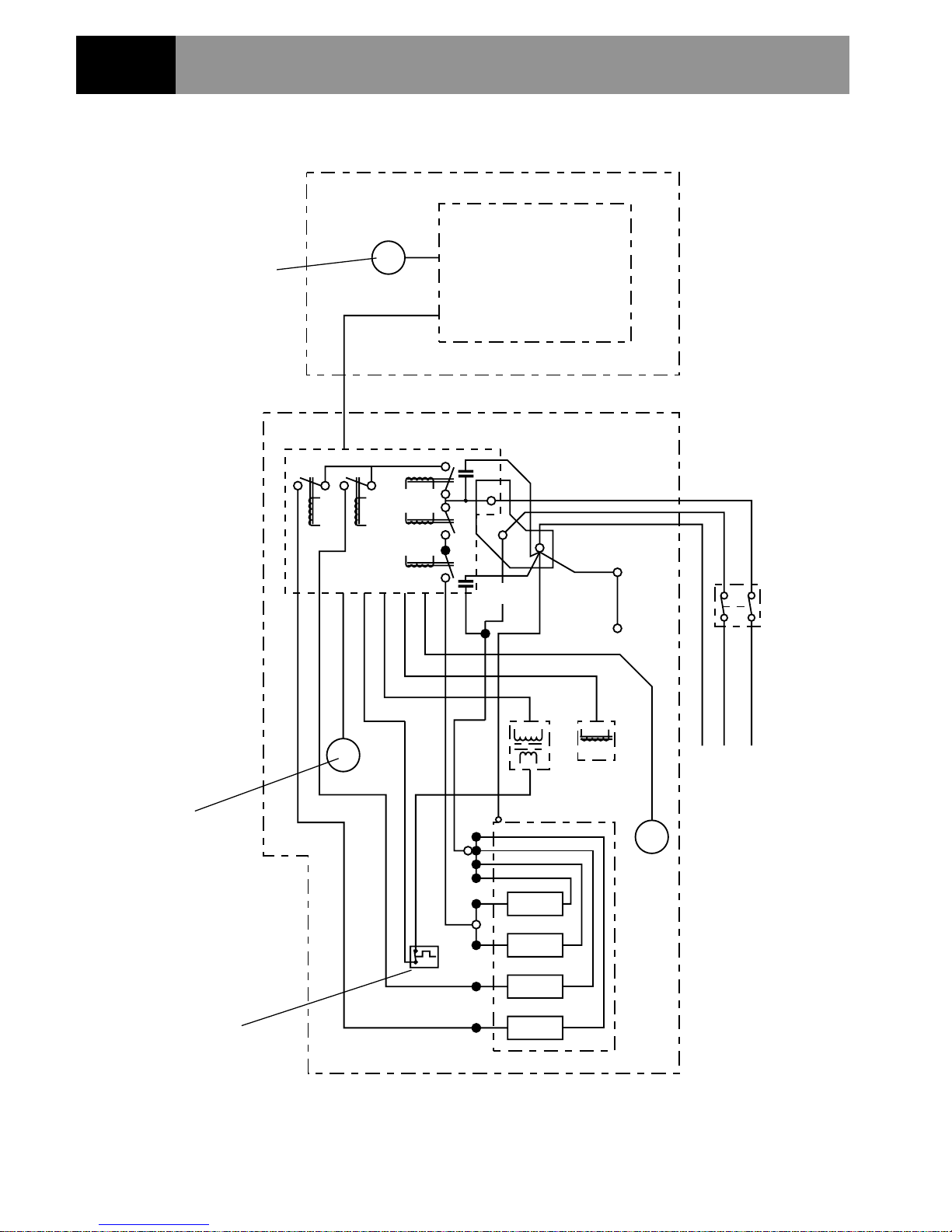
WirWir
WirWir
Wir
ing Diaging Diag
ing Diaging Diag
ing Diag
rr
rr
r
amam
amam
am
Section
Relay
Board
E
Inlet Sensors
Red
Brown (77)
Brown
Solenoid Valve
Transformer
230/240 V
AC Only
Green/Yellow
Brown
Double Pole Switch
45A Break Capacity
3 mm Contact Separation
L
N
PL2
PL1
Main Control Board
(78)
PL2
PL6
PL5
PL4
PL1
PL8
PL3
PL7
PL10
Green/Y
(75)
Inlet Outlet
Terminal Block
Outlet
Temperature
Sensor
One Shot
Thermal Trip
Temperature
Potentiometer
Blue
Heater Tank
Plumbing Connectors
PL12
PL11

1111
1111
11
Section
5
SpecificationsSpecifications
SpecificationsSpecifications
Specifications
1. Plumbing1. Plumbing
1. Plumbing1. Plumbing
1. Plumbing
1.1.1.1.
1.1.1.1.
1.1. The inlet connector assembly incorporates an inlet filter, which swivels to allow
these entry positions, top, top back, bottom and bottom back inlet.
1.2.1.2.
1.2.1.2.
1.2. The outlet terminates with a 1/2" BSP male thread for connection to a Mira
flexible shower hose.
1.3.1.3.
1.3.1.3.
1.3. A maintained pressure of at least
1 bar1 bar
1 bar1 bar
1 bar is recommended for the product up to a
maximum static pressure of
10 bar10 bar
10 bar10 bar
10 bar.
Thermostatic performance will be maintained down to
0.5 bar0.5 bar
0.5 bar0.5 bar
0.5 bar maintained
pressure. However, this will result in reduced power and therefore reduced flow.
1.4.1.4.
1.4.1.4.
1.4. The Mira Advance will provide satisfactory performance with incoming water
supply temperatures between 2°– 28°C.
1.5.1.5.
1.5.1.5.
1.5. Maximum ambient temperature for the Mira Advance whilst in use is 30°C.
2. Electrical2. Electrical
2. Electrical2. Electrical
2. Electrical
2.1.2.1.
2.1.2.1.
2.1. Mira Advance supply fuse - 8.7 kW 40 Amp
9.8 kW 45 Amp
2.2.2.2.
2.2.2.2.
2.2. The terminal block will not accept cable larger than 16 mm2.
2.3.2.3.
2.3.2.3.
2.3. The Mira Advance will provide satisfactory performance with an incoming
electricity supply voltage of 230 V ± 10%.
3.3.
3.3.
3.
Standards and Appro Standards and Appro
Standards and Appro Standards and Appro
Standards and Appro
vv
vv
v
alsals
alsals
als
3.1.3.1.
3.1.3.1.
3.1. The Mira Advance has been designed to comply with the requirements of the
British Electrotechnical Approvals Board (BEAB) and the requirements of UK
Water Regulations/Bylaws (Scotland).
3.2.3.2.
3.2.3.2.
3.2. This Mira Advance complies with all relevant directives for CE marking.
1212
1212
12
1. Plumbing1. Plumbing
1. Plumbing1. Plumbing
1. Plumbing
Read the section
"Important Safety Information""Important Safety Information"
"Important Safety Information""Important Safety Information"
"Important Safety Information" first.
1.1.1.1.
1.1.1.1.
1.1. A maintained pressure of at least
1 bar1 bar
1 bar1 bar
1 bar is recommended for the product up to a
maximum static pressure of
10 bar10 bar
10 bar10 bar
10 bar.
Thermostatic performance will be maintained down to
0.5 bar0.5 bar
0.5 bar0.5 bar
0.5 bar maintained
pressure. However, this will result in reduced power and therefore reduced flow.
1.2.1.2.
1.2.1.2.
1.2. The Mira Advance is suitable for installation within the shower area and must be
positioned over a water catchment area with the controls at a convenient height
for the user. The shower fitting should be positioned so that it discharges down
the centre line of the bath, or across the opening of a shower cubicle, and must
be directed away from the Mira Advance.
1.3.1.3.
1.3.1.3.
1.3. The Mira Advance is fitted with an inlet connector assembly that is designed to
accept plumbing supplies from the top, bottom or back. The water supply can be
fed with 15 mm pipe or 10 mm microbore pipe, suitably reduced into the inlet
connector assembly. If 10 mm microbore is used, then an allowance for
increased pressure loss must be made to ensure that the minimum maintained
inlet pressure is achieved (see note above).
1.4.1.4.
1.4.1.4.
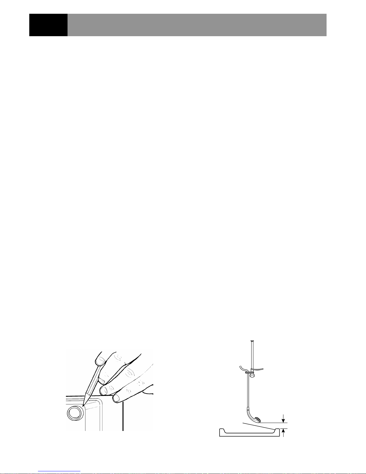
1.4. The Mira Advance must be fitted
ONTOONTO
ONTOONTO
ONTO the finished wall surface i.e. on top
of the tiles.
DO NOTDO NOT
DO NOTDO NOT
DO NOT block the air ventilation gaps around the sides of the
unit, either by tiling up to the sides of the unit or by using a sealant around
the case (Small pillars moulded on to the back of the case allow air
circulation). This Mira Advance is designed to be ventilated. Failure to do
this may cause product failure (Refer to Figure 1).
1.5.1.5.
1.5.1.5.
1.5. Use only the inlet connector assembly supplied with the Mira Advance, do not
use any other types of fitting.
Section
6
Installation RequirementsInstallation Requirements
Installation RequirementsInstallation Requirements
Installation Requirements
Figure 1Figure 1
Figure 1Figure 1
Figure 1
Figure 2Figure 2
Figure 2Figure 2
Figure 2
Spill-over Level
25 mm minimum

1313
1313
13
1.6.1.6.
1.6.1.6.
1.6.
Do not install the Mira Advance in a position where it may becomeDo not install the Mira Advance in a position where it may become
Do not install the Mira Advance in a position where it may becomeDo not install the Mira Advance in a position where it may become
Do not install the Mira Advance in a position where it may become
frozen. frozen.
frozen. frozen.
frozen. The shower unit must not be fitted where it may be exposed to
freezing conditions. Do not operate the unit if suspected of being frozen.
1.7.1.7.
1.7.1.7.
1.7. When installing the inlet connector for back inlet supply (refer to
InstallationInstallation
InstallationInstallation
Installation)
connection, it is advisable to seal around the incoming mains-fed supply to
prevent water ingress into the wall.
1.8.1.8.
1.8.1.8.
1.8. We recommend that a non-restrictive (free flowing) isolating valve is fitted in the
cold water supply pipe to allow the complete maintenance of the Mira Sport.
DoDo
DoDo
Do
notnot
notnot
not use a valve with a loose washer plate (jumper) as this can lead to a build up
of static pressures.
1.9.1.9.
1.9.1.9.
1.9. The Mira Advance is fitted with a 1/2" BSP male outlet thread, to accept a Mira
shower hose.
1.10.1.10.
1.10.1.10.
1.10. Refrain from applying excessive force when making any connections. Always
provide mechanical support when making the plumbing connections.
1.11.1.11.
1.11.1.11.
1.11. To avoid damage to the case when soldered fittings are used, pre-solder the
pipework and fittings before connecting them to the inlet connector assembly.
Note!Note!
Note!Note!
Note! Supply pipework MUST be flushed to clear debris before connecting the
Mira Advance.
Debris will reduce the performance of the unitDebris will reduce the performance of the unit
Debris will reduce the performance of the unitDebris will reduce the performance of the unit
Debris will reduce the performance of the unit.
1.12.1.12.
1.12.1.12.
1.12. When installed in very hard water areas (above 200 ppm temporary
hardness) your installer may advise the installation of a water treatment
device, to reduce the effects of limescale formation. Mira Sport malfunction
due to excessive limescale formation is not covered by the manufacturer’s
guarantee. Your local water company will be able to advise the hardness of
water in your area.
1.13.1.13.
1.13.1.13.
1.13. A hose retaining ring is supplied to prevent the handset from dropping below
the spillover level of the bath or shower, which could lead to contamination
from backsiphonage (refer to Figure 2). The supplied hose retaining ring
should meet the great majority of user requirements for shower installations
with flexible outlet fittings. However, there will be occasions when the hose
retaining ring will not provide a suitable solution. In these instances an
outletoutlet
outletoutlet
outlet double checkvalve, e.g. the Mira DCV-H,
mustmust
mustmust
must be fitted. The
inclusion of the Mira DCV-H will increase the required supply pressure
typically by 0.1 bar.
Double checkvalves, fitted in the inlet supply to the appliance, cause a
pressure buildup, which could exceed the maximum static inlet pressure for
the appliance.
1.14.1.14.
1.14.1.14.
1.14. Avoid layouts where the shower hose will be sharply kinked. This may reduce the
life of the hose.

1414
1414
14
2. Electrical2. Electrical
2. Electrical2. Electrical
2. Electrical
Read the section
"Important Safety Information""Important Safety Information"
"Important Safety Information""Important Safety Information"
"Important Safety Information" first.
2.1.2.1.
2.1.2.1.
2.1. The electrical installation must comply with the “Requirements for Electrical
Installations” commonly referred to as the IEE Wiring Regulations, or any
particular regulations and practices, specified by the local electricity supply
company in force at the time of installation.
2.2.2.2.
2.2.2.2.
2.2. In a domestic installation, the rating of the electricity supply company fuse and
the consumer unit must be adequate for the additional demand. As these Mira
Advances are high power units, it is essential to contact your electricity supply
company to ensure that the supply is adequate for the Mira Advance. Voltage
drop due to local heavy demand will reduce the shower's performance.
2.3.2.3.
2.3.2.3.
2.3. The Mira Advance
must be earthedmust be earthed
must be earthedmust be earthed
must be earthed by connecting the supply-cable earth
conductor to the earth terminal.
Supplementary bonding:Supplementary bonding:
Supplementary bonding:Supplementary bonding:
Supplementary bonding: Within the bathroom or shower room, all
accessible conductive parts of electrical equipment and extraneous
conductive parts that are likely to introduce earth potential, must be
electrically bonded to earth using a minimum cable size of 4.0 mm
2
if the
cable is not mechanically protected (2.5 mm2 if mechanically protected).
2.4.2.4.
2.4.2.4.
2.4. The minimum cable size (cross-sectional area) required is 6 mm2 under
normal conditions of installation.
Important!Important!
Important!Important!
Im p o r t a nt! The shower circuit should be separated from other circuits by at
least twice the diameter of the cable or conduit and it should not be run
through thermally insulating material or in locations where the ambient
temperature is likely to exceed 30 °C. If any of these conditions are
unavoidable it is necessary to determine the cable size which will prevent
damage to the cable caused by overheating.
2.5.2.5.
2.5.2.5.
2.5. Do not turn-on the electrical supply until the plumbing has been completed.
2.6.2.6.
2.6.2.6.
2.6. A separate, permanently connected supply must be taken from the consumer
unit to the Mira Advance through a double-pole switch, which has at least
3 mm contact separation. The switch can be a ceiling mounted pull-cord type
within the shower room or a wall mounted switch in an adjacent room.
The minimum cable size required is 6 mm2. To minimise voltage drop, and
thereby maximise performance, use the shortest possible cable route from the
consumer unit to the Mira Advance.
1515
1515
15
5
6
4
7
3
8
2
9
1
L
o
w
P
r
e
s
s
u
r
e
H
i
g
h
Medium
L
o
w
S
to
p
Te
m
p
e
ra
tu
re
S
e
r
v
i
c
e
Flow
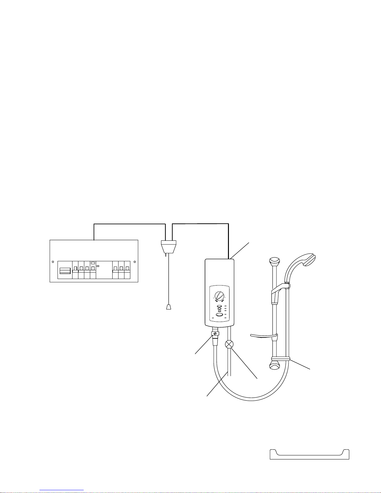
Plumbing and Electrical Schematic DiagramPlumbing and Electrical Schematic Diagram
Plumbing and Electrical Schematic DiagramPlumbing and Electrical Schematic Diagram
Plumbing and Electrical Schematic Diagram
Figure 3Figure 3
Figure 3Figure 3
Figure 3
Mira Advance
Optional Outlet
Double Checkvalve
Double-pole
Isolating Switch
Hose
Retaining
Ring
Mains-fed Cold
Water Supply
Consumer Unit
Isolating Valve
2.7.2.7.
2.7.2.7.
2.7. A 30 mA RCD
MUSTMUST
MUSTMUST
MUST be fitted. This may be part of the consumer unit or a
separate unit.
Note!Note!
Note!Note!
Note! The terminal block will not accept cable larger than 16 mm2.
2.8.2.8.
2.8.2.8.
2.8.
DO NOTDO NOT
DO NOTDO NOT
DO NOT twist the individual cable cores of the live and neutral conductors,
as this will prevent them from entering the terminal block.
2.9.2.9.
2.9.2.9.
2.9.
DO NOTDO NOT
DO NOTDO NOT
DO NOT exert strain on the terminal block.
2.10.2.10.
2.10.2.10.
2.10.
DO NOTDO NOT
DO NOTDO NOT
DO NOT turn-on the electrical supply until the plumbing has been
completed.
 Loading...