

Page 1

User Guide
11/2017 v.1.0
en
October 2017 v.1.02017 v.1.2
with MiR Robot Interface 2.0
Page 2

For more material,
go to our website
Copyright and disclaimer
All rights reserved. No parts of this manual may be reproduced in any form without the express written
permission of Mobile Industrial Robots ApS (MiR). MiR makes no warranties, express or implied, in respect
of this document or its contents. In addition, the contents of the document is subject to change without
prior notice. Every precaution has been taken in the preparation of this manual. Nevertheless, MiR
assumes no responsibility for errors or omissions or any damages resulting from the use of the
information contained.
Copyright © 2016 - 2017 by Mobile Industrial Robots
Contact the manufacturer:
Mobile Industrial Robots
Emil Neckelmanns Vej 15F
DK-5220 Odense SØ
www.mir-robots.com
Phone: +45 20 377 577
E-mail: [email protected]
CVR: 35251235
Page 3

Table of contents
1 About this manual .............................................................................................................3
1.1 Overview......................................................................................................................3
1.2 Document history ........................................................................................................3
1.3 Further information.....................................................................................................3
2 Safety .................................................................................................................................4
2.1 Overview......................................................................................................................4
2.2 Safety concept .............................................................................................................4
2.3 General safety instructions..........................................................................................5
2.3 1 Warning notes ..................................................................................................5
2.3 2 Caution notes....................................................................................................6
2.3 3 Notices ..............................................................................................................7
2.4 Lithium battery ............................................................................................................7
2.5 Safety circuit ................................................................................................................8
2.6 Applied standards........................................................................................................8
3 Getting Started ..................................................................................................................9
3.1 The shipment...............................................................................................................9
3.2 Unpacking the MiR100™............................................................................................10
3.2 1 Unboxing.........................................................................................................10
3.2 2 Powering up....................................................................................................11
3.3 Getting connected .....................................................................................................13
3.4 Charging the robot.....................................................................................................14
3.5 Testing the robot .......................................................................................................15
3.6 Shutting down the robot ...........................................................................................16
4 Product presentation.......................................................................................................17
4.1 About the MiR100™...................................................................................................17
4.2 Identification label.....................................................................................................17
4.3 MiR100™ Outer parts ................................................................................................18
4.4 MiR200™ Inner parts .................................................................................................19
4.5 Sensor systems ..........................................................................................................20
4.6 Light indicators ..........................................................................................................20
4.7 Main features of the MiR100™..................................................................................20
5 Accessories ......................................................................................................................22
5.1 Overview....................................................................................................................22
5.2 Placing the top module..............................................................................................22
6 Technical specifications ...................................................................................................23
6.1 Main specifications....................................................................................................23
6.2 Dimension drawing....................................................................................................25
7 Maintenance....................................................................................................................26
7.1 Overview....................................................................................................................26
7.1 1 Regular cleaning .............................................................................................26
7.1 2 Regular checks and replacements ..................................................................26
8 Troubleshooting ..............................................................................................................28
Page 4

9 Repacking for transport...................................................................................................29
9.1 Preparations ..............................................................................................................29
9.2 Packing the robot for transportation.........................................................................29
10 Payload specifications ...................................................................................................30
11 Declaration of conformity..............................................................................................34
12 Neutrik connector..........................................................................................................36
Appendices
Payload specifications ......................................................................................................... 33
MDeclaration of conformity................................................................................................ 36
Neutrik connector ............................................................................................................... 38
Page 5

•
•
•
•
•
•
MiR100™ User Guide, Robot Interface 2.0, 11/2017 v.1.0 3
• • • • • •
1 About this manual
1.1 Overview
This User Guide contains all essential information about how to start up and operate a MiR100™
robot. It also includes necessary information about safe handling of the robot, technical
specifications, troubleshooting and guidelines for proper maintenance of the robot. The User Guide
is intended for Mobile Industrial Robots’ distributors as well as end users responsible for the daily
operation of the MiR100™ robot.
This user guide describes the MiR100 with Robot Interface 2.0. There is a corresponding user guide
for the MiR100 with Web Interface 1.0.
1.2 Document history
This table shows latest and previous versions of this document and their interrelation with product
software releases.
1.3 Further information
You can download all manuals from the MiR website where you will also find training videos,
product pictures and technical specifications.
• Manuals and more: www.mobile-industrial-robots.com/products
Your MiR distributor is your first point of contact for all service queries. Find distributor contact on
our website.
• Distributor contact info: www.mobile-industrial-robots.com/distributors.
Doc version Release date Description SW release HW version
1.0 2017-11-27 First edition 2.0.2 1.0
Page 6

•
•
•
•
•
•
MiR100™ User Guide, Robot Interface 2.0, 11/2017 v.1.0 4
• • • • • •
2Safety
2.1 Overview
This manual contains notices you have to observe to ensure your personal safety, as well as to
prevent damage to property. The notices referring to your personal safety are highlighted in the
manual by a safety alert symbol. The notices shown below are graded by signal words to indicate
degree of danger.
2.2 Safety concept
Indicates an immanently hazardous situation that
will
result in death or severe personal injury if proper
precautions are not taken.
Indicates a potentially hazardous situation that
could
result in death or severe personal injury if proper
precautions are not taken.
Indicates a situation that
could
result in minor personal injury or damage to the equipment if proper
precautions are not taken.
Indicates a situation that
could
result in property damage if proper precautions are not taken.
Page 7
•
•
•
•
•
•
Safety
MiR100™ User Guide, Robot Interface 2.0, 11/2017 v.1.0 5
2.3 General safety instructions
This section contains general safety notes. Some safety notes are repeated or further specified in
other sections of the manual and further safety notes are present throughout the manual.
2.3.1 Warning notes
•
Ensure proper mounting of loads during transport
Danger of personal injury from overturning robot or falling load.
All accessories and loads mounted on top of the robot should be fastened correctly and meet specifications.
See on page 30.
•
Avoid leakage of fluid during transport
Danger of personal injury from leaking fluid.
Make sure that loads containing fluids do not leak during transport.
•
Use only the original charger
Danger of personal injury and/or damage to the robot.
Use of other charger than the one supplied by the manufacturer can ruin the battery and may cause fire.
•
Update maps to avoid hazards on the route
Danger of personal injury and/or damage to the robot.
Make sure to update maps with areas without drive surfaces such as stairways.
•
Update maps to avoid hazards on the route
Danger of personal injury and/or damage to the robot.
Make sure to update maps to avoid driving in hazardous zones such as close to stairways.
•
Do not drive vehicle irresponsibly
Danger of personal injury and/or damage to the robot.
The robot should not be driven over edges or in other ways operated irresponsibly.
Page 8
•
•
•
•
•
•
Safety
MiR100™ User Guide, Robot Interface 2.0, 11/2017 v.1.0 6
2.3.2 Caution notes
•
Do not use the robot to transport people
Risk of personal injury and/or damage to the robot.
The robot should never be used to transport people. This will revoke compliance with the standard EN 1525
Safety for unmanned trucks.
•
Avoid gradients above 5% on the route
Risk of personal injury and/or damage to the robot.
The surface grade (ramps etc.) cannot exceed 5% as this may cause the robot to skid.
•
Only drive on even and dry surface
Risk of personal injury and/or damage to the robot.
Wet and uneven surfaces may cause the robot to skid.
•
Do not overload the robot
Risk of personal injury and/or damage to the robot.
The maximum payload for the load on top of the robot is 200 kg 440 lbs kg. If exceeded, it may cause
overturning, falling load and damage to the robot. See also Appendix .
•
Do not use robot on board ships
Risk of personal injury and/or damage to the robot.
Unstable surface caused by moving vessel may cause the robot to skid.
•
Turn off the main power immediately after removal of the top cover
Risk of personal injury and/or damage to the robot.
Turn off main power relay to avoid short circuit. See Product presentation on page 17
Page 9
•
•
•
•
•
•
Safety
MiR100™ User Guide, Robot Interface 2.0, 11/2017 v.1.0 7
2.3.3 Notices
2.4 Lithium battery
Lithium batteries are primary power sources with high energy content designed to represent the
highest possible degree of safety.
•
Indoor use only
Risk of damage to the robot.
The robot is made for indoor use only and should never be used outdoor.
•
Avoid small objects on the floor in the robot’s area
Risk of property damage and/or minor damage to the robot.
The robot cannot detect obstacles lower than 50 mm and may overrun smaller objects.
•
Remove unwanted objects from the floor in the robot’s area
Risk of inefficient execution of orders.
The robot will go around objects that are not parts of the map, but this may influence the efficiency of the
planned route.
•
Avoid overheating of components
Risk of damage to the robot or robot components.
The ambient temperature in the robot’s environment must not exceed 50° C - 122° F.
•
Avoid exposure of the robot to excessively humid or dry environment
Risk of damage to the robot or robot components.
The ambient humidity in the robot’s environment must be within the specifications, see Technical
specifications on page 23.
Potential hazard
Lithium battery packs may get hot, explode or ignite and cause serious injury if they are abused
electrically or mechanically.
Observe the following precautions handling and using lithium batteries:
• Shut off the battery when not in use.
• Do not short-circuit, recharge or connect with false polarity.
• Do not expose to temperature beyond the specified temperature range or incinerate the battery.
• Do not crush, puncture or disassemble the battery. The battery contains safety and protection devices, which,
if damaged, may cause the battery to generate heat, explode or ignite.
• Do not allow the battery to get wet.
• In the event the battery leaks and the fluid gets into one’s eye, do not rub the eye. Rinse well with water and
immediately seek medical care. If left untreated, the battery fluid could cause damage to the eye.
• Use only the original charger and always follow the instructions from the battery manufacturer.
Page 10
•
•
•
•
•
•
Safety
MiR100™ User Guide, Robot Interface 2.0, 11/2017 v.1.0 8
2.5 Safety circuit
If a person or other moving object enters the safety zones of the robot where the planner due to
response time, errors etc. does not respond, the safety circuit will force the robot into emergency
stop, and the robot stops immediately. When the person or object is out of the safety zone again,
the robot will automatically reset the emergency stop.
MiR100™ is designed with total redundant electrical safety circuit including Sick Safety components.
If any internal errors in the safety circuit occur, the robot will immediately go into emergency stop
which means that all moving parts will be voltage free by mechanical disconnection. Only when the
redundancy is provided, it is possible to reset the emergency stop and continue.
2.6 Applied standards
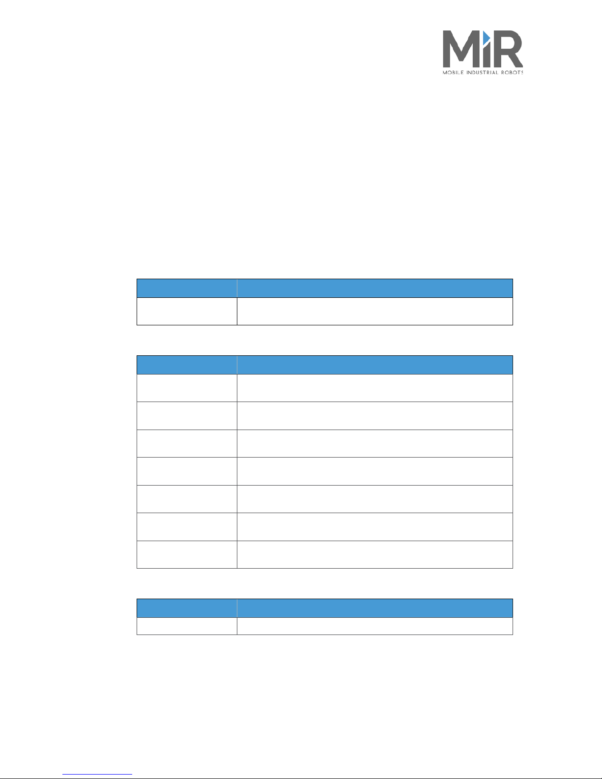
The MiR100™ fulfills all relevant provisions of the following EU directives or regulations:
Reference to the harmonized standards used, as referred to in Article 7(2):
Reference of the other technical standards and specifications used:
See also signed copy of Declaration of conformity in Declaration of conformity on page 34.
Ref. no. Title
2006/42/EC
Directive 2006/42/EC of the European Parliament and of the Council of 17 May
2006 on machinery, and amending Directive 95/16/EC (recast) (1).
Ref. no. Title
EN
60204-1:2206/A1:2009
Safety of machinery – Electrical equipment of machines – Part 1: General
requirements
EN ISO 12100:2010-11 Safety of machinery – General principles for design – Risk assessment and risk
reduction (ISO 12100:2010)
EN ISO 13849-1:2015 Safety of machinery – Safety related parts of control systems – Part 1: General
principles for design (ISO 13849-1:2015)
EN ISO 13849-2:2012 Safety of machinery – Safety related parts of control systems – Part 2: Validation
(ISO 13849-2:2012)
EN ISO 13850:2015 Safety of machinery – Emergency stop function – Principles for design (ISO
13850:2015)
EN 60204-1:2006-6 Safety of machinery – Electrical equipment of machines – Part 1: General
requirements
EN 1175-1:1998+A1:2010 Safety of industrial trucks – Electrical requirements – Part 1: General
requirements for battery powered trucks
Ref. no. Title
EN 1525:1997-09 Safety of industrial trucks – Driverless trucks and their systems
Page 11
•
•
•
•
•
•
MiR100™ User Guide, Robot Interface 2.0,
11/2017 v.1.0
9
• • • • • •
3 Getting Started
3.1 The shipment
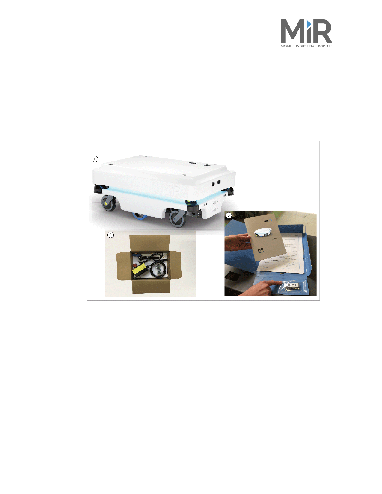
Figure 3.1. Figure 3.1 The shipment
1. The robot
2. MiR 100 Kit
- Emergency stop box, external antenna and 4 pcs. M10x40 bolts
- Charging cable
3. MiR folder containing:
- Printed documents: Quick start, CE declaration of conformity, mounting instructions for emergency stop
- USB flash drive: Getting started video, MiR100™ User guide, CE declaration of conformity, other manuals.
Page 12
•
•
•
•
•
•
MiR100™ User Guide, Robot Interface 2.0,
11/2017 v.1.0
10
3.2 Unpacking the MiR100™
3.2.1 Unboxing
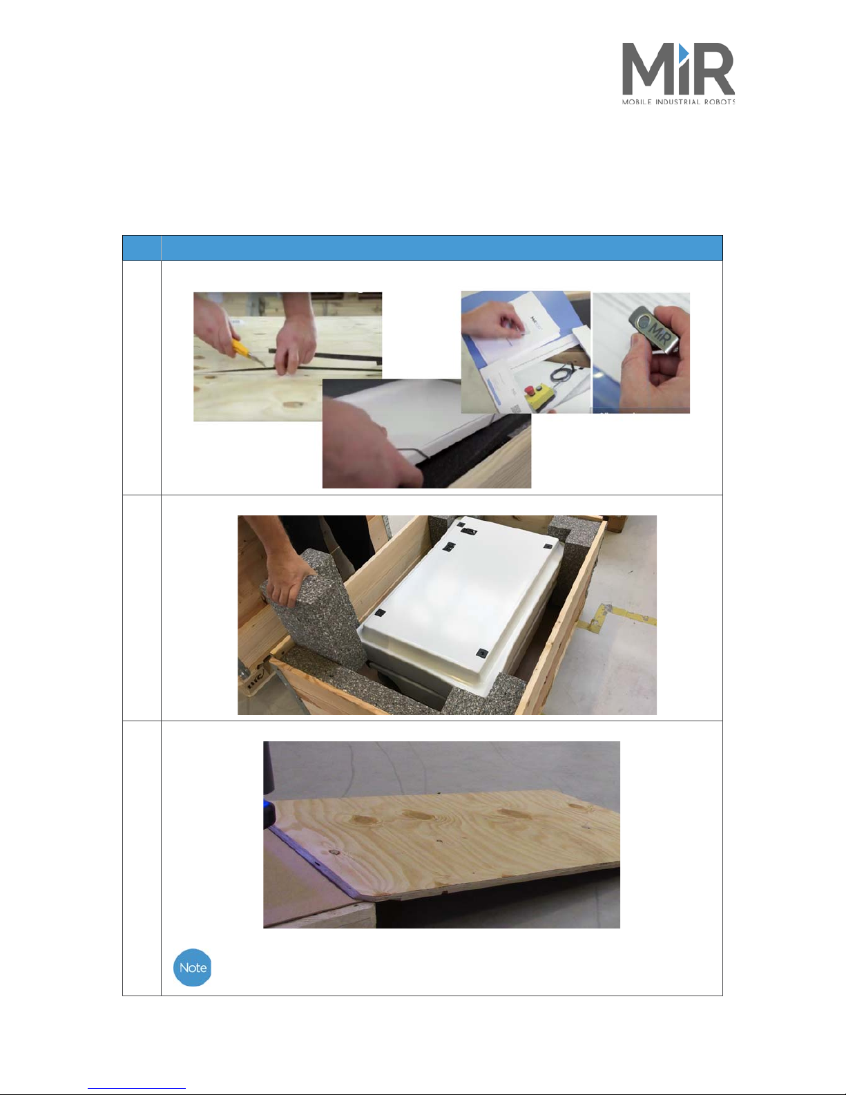
Follow these steps to unbox the MiR100™
Step Action
1
Remove pallet lid and take out folder with printed documents and USB flash.
2
Remove the top foam, foam blocks on the sides and the pallet frames.
3
Place the pallet cover as a ramp at the robot’s rear end.
Keep the packaging for any future transportation of the robot.
Page 13
•
•
•
•
•
•
MiR100™ User Guide, Robot Interface 2.0,
11/2017 v.1.0
11
3.2.2 Powering up
Step Action
1
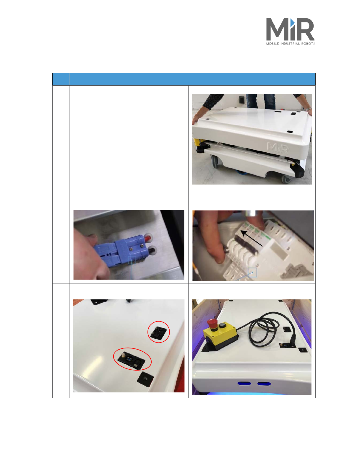
Grab the two rounded corners and carefully lift
off the cover.
2
Connect the battery cable to the plug on top of
the battery box.
Switch on the four relays placed in the corner by
the front laser scanner. Start with 32A main power,
i.e. from the outer frame in.
3
Carefully fit the cover correctly over the
connector openings.
Mount and connect the emergency stop box on
top of the robot cover.
Page 14
•
•
•
•
•
•
MiR100™ User Guide, Robot Interface 2.0,
11/2017 v.1.0
12
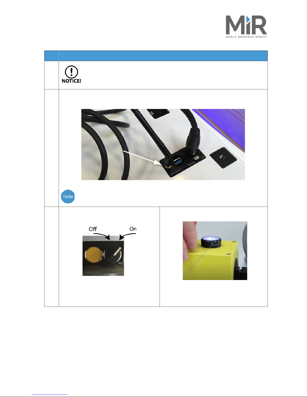
If a top module is going to be mounted on top of the robot, the emergency stop must
be placed in a position where it is easy to reach. See Placing the top module on
page 22.
4
Connect the antenna to the connector on top of the robot cover. Remove the plastic cap from the
connector before fixing the antenna.
The antenna can be lowered and rotated in all directions to fit under a top module.
5
Turn on the power switch.
The robot lights up with a yellow running light
for a short moment, then enters emergency
stop mode indicated by a constant red light.
Press the reset button on the emergency stop
when it has lit up.
The robot light now switches to yellow constant
light, indicating that the robot is paused and ready
to operate.
Step Action
Page 15

•
•
•
•
•
•
MiR100™ User Guide, Robot Interface 2.0,
11/2017 v.1.0
13
3.3 Getting connected
Step Action
1
On a PC or tablet, go to the WiFi
menu, find the name of your robot
and connect to it. Password:
mirex4you
Open a b row se r and g o to mir.com.
Log in to the MiR Robot interface
using the default username
Distributor and password
distributor.
2
When logged in, press Manual
control on the joystick icon to put
the robot in manual driving mode,
and use the joystick to drive the
robot down the ramp
The robot light switches
to blue, indicating that
the robot is in manual
mode and can be
controlled by the
joystick.
3
It is recommended to reverse the robot down the ramp.
Page 16
•
•
•
•
•
•
MiR100™ User Guide, Robot Interface 2.0,
11/2017 v.1.0
14
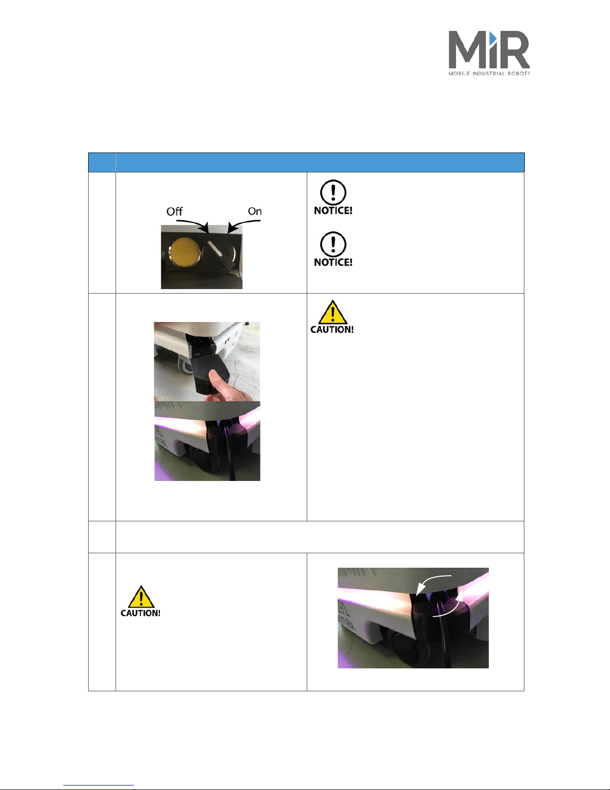
3.4 Charging the robot
The robot arrives with a charged battery and can drive for up to three hours before
recharging is required. Follow these steps to charge the robot using the enclosed cable:
Step Action
1
Turn off the robot on the button in the
robot’s front left-hand corner.
To avoid fast discharging, it is
recommended to turn off the robot
while charging.
Use only the original charging cable.
2
Pull off the rear corner cover, and connect
the charging cable to the charging socket.
Then connect the other end of the cable to a
power socket to start the charging
To avoid damage to the charging
so cket, it is imp ortant tha t th e ca ble be
connected to the robot’s charging
socket before it is connected to power.
After recharging, the cable must be
disconnected from power before it is
removed from the robot.
3
After a maximum of three hours, the robot is fully charged. The robot em its a gree n light when the
battery is charged.
4
Disconnect the charging cable.
To avoid overvoltage surge and
potential damage to the robot,
first remove the cable from the
power socket, then from the
robot.
To remove the cable from the robot, turn it
slightly to the left and pull.
Slide the rear corner cover back on.
Page 17

•
•
•
•
•
•
MiR100™ User Guide, Robot Interface 2.0,
11/2017 v.1.0
15
3.5 Testing the robot
Before using the robot, you are recommended to check that all components and processes
inside the robot work as intended.
1. Log on to the MiR Robot interface, see Getting connected on page 13.
2. Go to
Monitoring > Hardware health
.
3.
When all components in a group are OK, it is marked with a green dot. If one or more
components in a group are not in perfect condition, the group will be marked with a yellow
or red dot and you can expand the group by clicking on the green arrow and see which
components are not functioning correctly and why.
Figure 3.1. Extract of Hardware Health menu. Message: OK indicates that the components of the group
Page 18

•
•
•
•
•
•
MiR100™ User Guide, Robot Interface 2.0,
11/2017 v.1.0
16
3.6 Shutting down the robot
Follow these steps to shut down the robot correctly.
Step Action
1
Press the red emergency stop button. This will
turn off the power to the motors
2
Turn off the power switch. Wait for the light on the robot to turn
off. This means that there is no more
power going to the robot.
Page 19

•
•
•
•
•
•
MiR100™ User Guide, Robot Interface 2.0, 11/2017 v.1.0 17
• • • • • •
4 Product presentation
4.1 About the MiR100™
The MiR100™ is an automatic vehicle that can transport materials internally within production
facilities, hospitals, warehouses, and a host of other industrial locations.
The user provides the destination of product delivery via a web-based user interface. MiR100™ can
be set up to run a fixed route, be called on demand or perform more complex operations (missions).
It can also operate as part of a fleet of MiR robots, centrally controlled from a single web based user
interface.
The MiR100™ operates via a map which can be created the first time the vehicle is used. While
ope rat ing, the safe ty sc anner s ens ure th at th e robo t avo ids ob stacles (people, furniture) that are not
mapped. The internal map contains defined locations (office, product delivery, John's room, etc.)
that are used for logistical planning.
With a MiRCharge™ charging station the robot handles moving to a charging station automatically.
All it takes is the definition of a charging mission and a charing position in the map.
The robot is controlled from a website (HTML5), which is accessed via a browser on a PC,
smartphone or tablet
. Each vehicle has its own network. See separate setup sheet.
4.2 Identification label
The identification label of the MiR100™ is placed on the rear skirt of the robot.
Figure 4.1. MiR100™ identification label
•
CE Mobile Industrial Robots ApS declares that the MiR100™ meets the
requirements of the applicable EC directives. See Declaration of
conformity on page 34
•
Serial number The 15-digit serial number is a unique identifier of the robot. The last four
digits form part of the original name of the robot, e.g. MiR R500
• MiR100 1.9 Product name and hardware version.
Page 20

•
•
•
•
•
•
Product presentation
MiR100™ User Guide, Robot Interface 2.0, 11/2017 v.1.0 18
4.3 MiR100™ Outer parts
Figure 4.2. MiR100™ Outer parts
1. Top cover 11. Emergency stop connector
2. Caster wheel - all four corner wheels 12. USB port “service port” - connects to the robot’s
PC
3. Drive wheel - differential control 13. Antenna socket
4. On/Off button and scanner reset button (yellow) 14. Neutrik FCS FDL1-B connector - for connection to
hardware such as hook - see pin number layout in
Appendix C, Neutrik connector on page 36
5. HDMI port - behind the front corner cover 15. RJ45 Ethernet connection
6. USB port “service port” - connects to the robot’s PC 16. Mooring hole - one in each corner for top modules
7. Ultrasonic sensors 17. Rear laser scanner
8. Pad connectors - for connection to charging poles on
MiRCharge charging station
18. Rear skirt
9. 3D depth camera 19. Charging port - behind the rear corner cover
10. Front laser scanner 20. Side skirt
Page 21

•
•
•
•
•
•
Product presentation
MiR100™ User Guide, Robot Interface 2.0, 11/2017 v.1.0 19
4.4 MiR200™ Inner parts
Figure 4.3. MiR100™ Inner parts
1. Battery charger - internal 110/230 V charger for charging
of the battery
9. Optocoupler - communication for emergency stop
2. Breaker - automatic fuse between batteries and
components
10. Space for extra battery
3. Motor controller - manages the two motor drives 11. MiR board - interface board for gyroscope,
accelerometer, ultrasound and light
4. Brake relay - ensures immediate power cutoff in case of
power outage
12. 24/24 V switch mode power supply - provides
safety components. Ensures stable voltage
5. Redundant drive - relays controlled by SICK modules
supplying the motor controller
13. 5V power supply - power to the MiR board
6. Router - local network 14. Loud speaker
7. Battery with connector - main power to the robot 15. 12 V power supply - power to NUC and router
8. SICK safety modules - communication between sensor
signals and control of the robot.
16. NUC PC
Page 22
•
•
•
•
•
•
Product presentation
MiR100™ User Guide, Robot Interface 2.0, 11/2017 v.1.0 20
4.5 Sensor systems
The MiR100™ has a number of internal and external safety sensors to secure safe operation among
people and equipment.
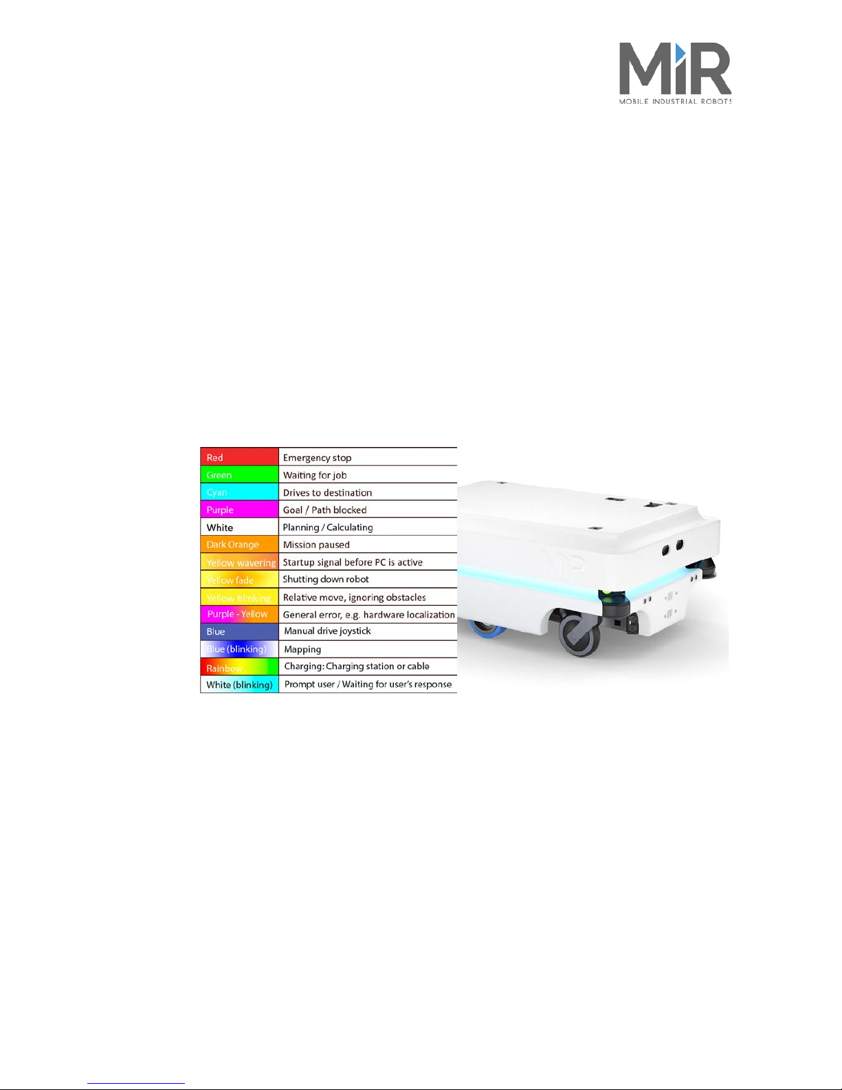
4.6 Light indicators
The light indicators on the MiR100™ indicate current operational state. Colors may be adapted to
individual user needs, but the robot is delivered with the following setup.
Figure 4.4. MiR100™ light indicators
4.7 Main features of the MiR100™
•
Driving in a populated workspace
The robot is designed to operate among people.
•
Overall route planning and local adjustments
The robot plans a general route to its target destinations. When the robot encounters obstacles
which are not in the map (like people and objects), adjustments are made to the route.
•
Sound and light signals
The robot continuously signals with light and sounds indicating its current mode, for example
waiting for job, driving to destination, destination reached or alert mode.
•
Planning of driving and receiving a package
A web interface, accessed from a PC, tablet or smartphone, gives easy access to operation and
monitoring of the robot.
External sensors
(see MiR100™ Outer parts on page 20)
Internal sensors
(see MiR100™ Outer parts on page 20
• 3D camera Gyro
• Laser scanners Motor encoder
• Ultrasonic scanners Detection of transparent objects
Page 23

•
•
•
•
•
•
Product presentation
MiR100™ User Guide, Robot Interface 2.0, 11/2017 v.1.0 21
•
Alert for ‘lost
’
If the robot enters a situation where it is unable to find a safe path to its destination, it stops,
turns on the yellow-purple running error light and a customer defined ‘catch’ action may be
used to alert people or take other actions.
•
Automatic deceleration for objects
The built-in sensors slow down the robot when obstacles are detected in front of it.
•
Optimal surface operation
s
The robot is made to run on a level, dry floor with a maximum grade of 5%. The sensors detect
and avoid objects from 50 mm above floor level.
•
Internal map
The MiR100™ uses an internal map for route planning. The robot ca n eith er use a floor plan
from a CAD system or create a map by manual navigation around the entire area in which
the robot is going to operate. When mapping, the robot’s sensors detect walls, doors,
furniture and then creates a map based on this input. After creation of the map, positions
and other features can be added in the map editor.
•
MiRHook
A hook may be mounted on the MiR100™ enabling it to tow carts with a payload of up to 300 kg.
Page 24

•
•
•
•
•
•
MiR100™ User Guide, Robot Interface 2.0, 11/2017 v.1.0 22
• • • • • •
5 Accessories
5.1 Overview
The MiR100™ can be equipped with a range of applications to suit the specific purpose the robot
will be used for. Some are user-provided and others are purchased directly from Mobile Industrial
Robots.
For instructions on how to mount an application, for example a top camera, please refer to the
relevant application manual found on Mobile Industrial Robot’s website or contact your distributor.
In the following, you can read the general rules for how to mount a top module.
5.2 Placing the top module
Top modules must be fastened using the self-tightening conically shaped mooring holes in each
corner of the robot and tightening torque: 47 Nm.
Figure 5.1. Top modules are fastened through the mooring holes in the top cover.
Before adding the to module, the emergency stop box must be removed and remounted
on the top module in a position where it is easy to reach.
The correct position must be
assessed in each individual case taking into account potential risks. Requirements of the
harmonized standard EN ISO 13850 should be followed.
Stay within the specifications for weight and the payload’s center of gravity, see Payload
specifications on page 30
Page 25

•
•
•
•
•
•
MiR100™ User Guide, Robot Interface 2.0, 11/2017 v.1.0 23
• • • • • •
6 Technical specifications
6.1 Main specifications
Dimensions
Length
890 mm
Width
580 mm
Height
352 mm
Height above floor
35 mm
Weight (without load)
62.5 kg
Load surface
600 x 800 mm
Color
Pure white: RAL 9010
Payload
Robot payload
100 kg (maximum 5% incline)
Towing capacity
300 kg
Speed and performance
Running time
10 hours or 20km
Maximum speed
Forwards: 1.5 m/s (5,4 km/h)
Backwards: 0.3 m/s (1 km/h)
Turning radius
520 mm around center of robot
Positioning accuracy
+/- 50 mm of position, +/- 10 mm to docking marker
Traversable gap and sill tolerance
20 mm
Page 26
•
•
•
•
•
•
Technical specifications
MiR100™ User Guide, Robot Interface 2.0, 11/2017 v.1.0 24
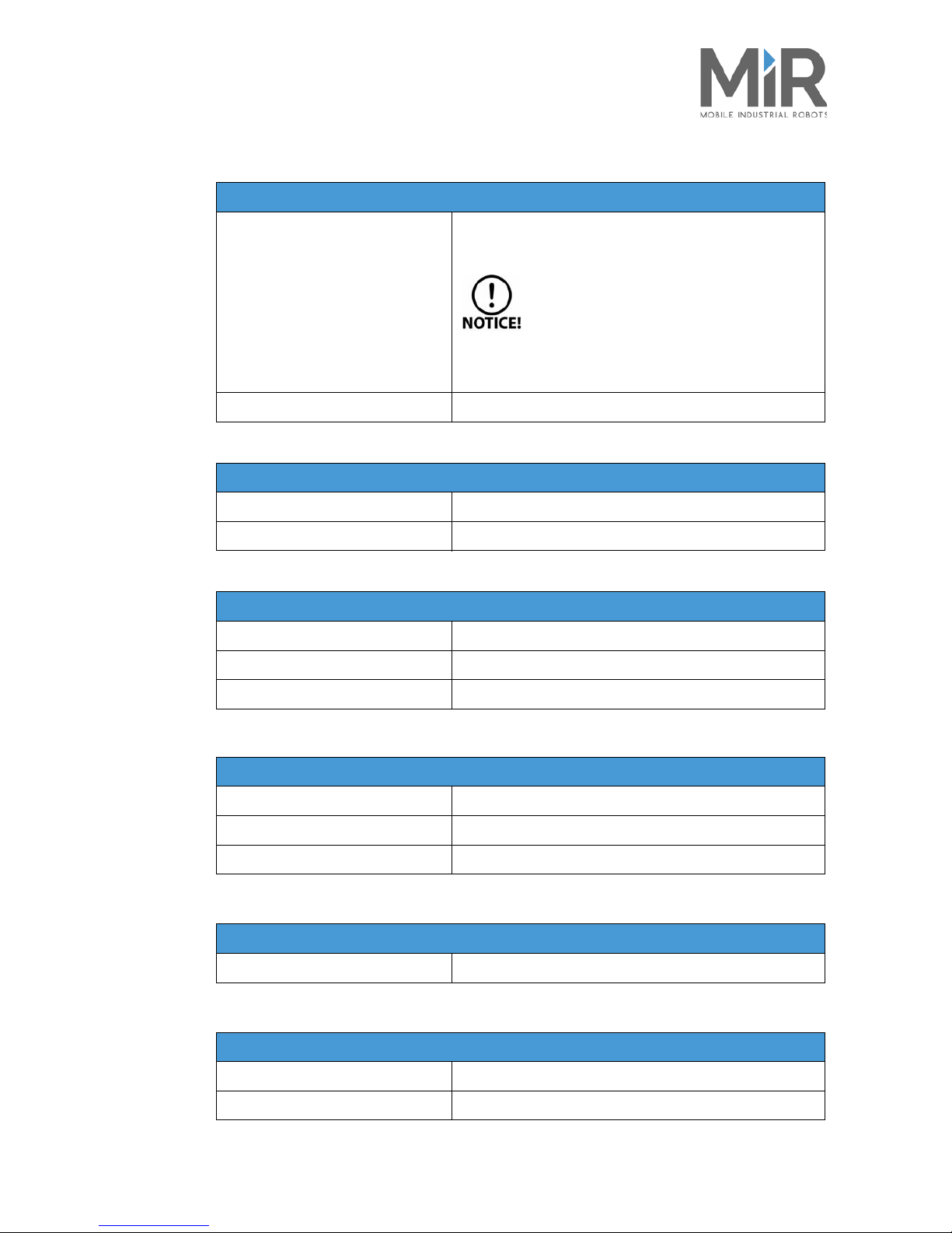
Power
Battery
Li-NMC, 24 V, 40 Ah; charging time: up to 3 hours (0-80% in 2
hours)
See safety notes for the battery in “Lithium battery”
on page 7.
See also requirements for battery transportation in
“Repacking for transport” on page 29.
Internal charger
Input: 100-230 V ac, 50-60 Hz / Output: 24 V, max 15 A
Environment
Ambient temperature range
+5° C to 50°C (humidity 10-95% non-condensing)
IP class
IP 20
Communication
WiFi
Dual-band wireless AC/G/N/B
Bluetooth
4.0 LE, range: 10-20 m
I/Os
USB and Ethernet
Safety sensors
SICK laser scanners S300 (2 pcs)
360° visual protection around robot
3D camera Intel RealSense™
Detection of objects ahead 50-500 mm above floor
Ultrasonic scanners (4 pcs)
Detection of transparent objects ahead, e.g. glass doors
Safety compliance and approvals
Compliance with
EN 1525, PLd cat. 3, ESD approved and CE certified
Top module
Max height from floor to top
1800 mm
Center of gravity
Lower than 900 mm above the floor
Page 27

•
•
•
•
•
•
Technical specifications
MiR100™ User Guide, Robot Interface 2.0, 11/2017 v.1.0 25
6.2 Dimension drawing
Figure 6.1. Dimensions of the MiR100™
Page 28
•
•
•
•
•
•
MiR100™ User Guide, Robot Interface 2.0, 11/2017 v.1.0 26
• • • • • •
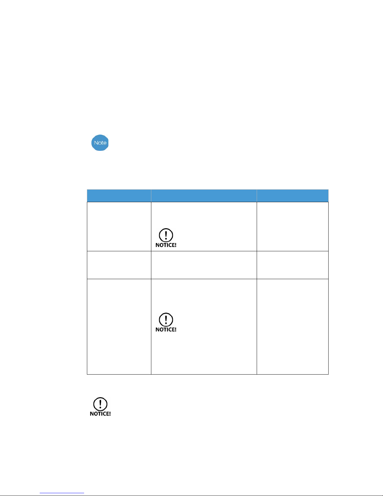
7 Maintenance
7.1 Overview
The following maintenance schedules give an overview of regular cleaning and parts replacement
procedures.
The stated intervals are indicative and depend on the operating environment and frequency
of usage of the robot.
7.1.1 Regular cleaning
This table gives an overview of maintenance tasks for the MiR100™
7.1.2 Regular checks and replacements
Before starting replacement tasks that involve removal of the shield:
•Turn off the robot, see Shutting down the robot on page 16
•Remove the shield and unplug the ESD cable if applied, see Getting connected on
page 13
•Turn off relays and unplug the battery, see Powering up on page11
Part Maintenance Interval
Robot
Clean the robot on the outside with a
damp cloth.
Do not use compressed air.
as needed
Wheels
Remove dirt with a cloth, and make
sure nothing is entangled in the
wheels.
2-3 weeks / as needed
Laser scanners
Clean the optics covers of the scanners
for optimum performance. Avoid
aggressive or abrasive cleaning agents.
Static charges cause dust
particles to be attracted to the
optics cover. You can diminish
this effect by using the anti-
static plastic cleaner (SICK part no.
5600006) and the SICK lens cloth (part no.
4003353). See the manufacturer’s own
documentation.
weekly / as needed
Page 29
•
•
•
•
•
•
Maintenance
MiR100™ User Guide, Robot Interface 2.0, 11/2017 v.1.0 27
Part Maintenance Interval
Caster wheels (the four
corner wheels)
Check bearings and tighten. Replace as needed.
Drive wheels (the two
middle wheels)
Check wheel surface for wear. Replace as needed.
The robot must be
calibrated after
replacement of the
wheels.
Emergency stop
To check that the emergency stop
works, push down the red button
and check that the emergency reset
button lights up.
3-4 months / according to
EN/ISO 13850 Safety of
machinery - Emergency stop
function
LED light band
Check if the LED light band is intact.
Does the light show all the way
around the robot?
Every 3-4 months
Laser scanners
Check for visual defects. Replace as needed.
The robot must be
calibrated after
replacement of the
wheels.
Battery
Check if it discharges to fast. Replace every two years or
1000 cycles
Page 30
•
•
•
•
•
•
MiR100™ User Guide, Robot Interface 2.0, 11/2017 v.1.0 28
• • • • • •
8 Troubleshooting
If the robot experiences an emergency stop and cannot be restarted by pressing
Continue
in the MiR100™ user interface, then pull it to an unobstructed area.
Error/Situation Remedy
The robot stops on its way to
a destination
• Check if the destination is blocked.
• Make sure the robot’s destination corresponds with its position in the
map.
• Check that the camera is unobstructed.
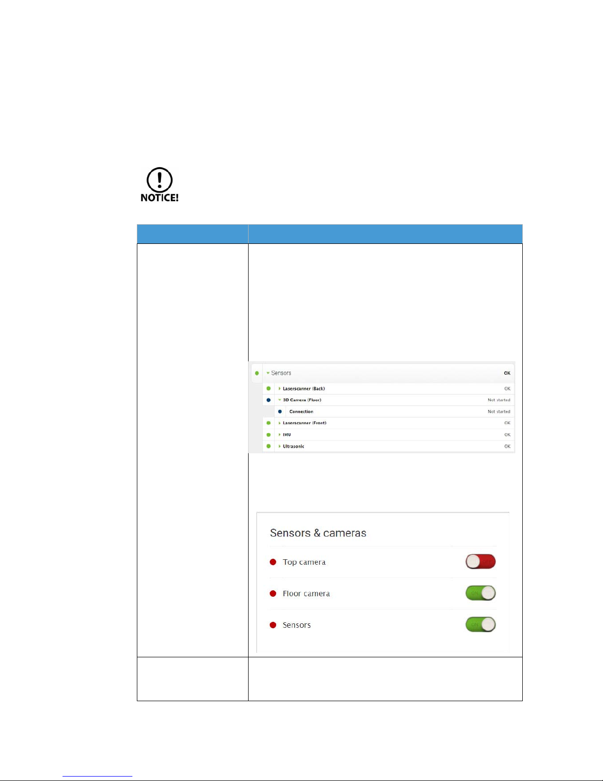
• Check that the wheels are unobstructed and not tangled up in anything.
• Check that the status is OK: in the MiR user interface, go to
Monitoring
> Hardware Health
. Tap to open the group
Sensors
and check that
3D
Camera (Floor)
is on.
If it shows
Not started,
then go to the
Processes
menu to turn it on:
System> Procceses
. Find Sensors & cameras> Floor camera and turn on
the camera.
The robot is turned on, but it
will not start a mission.
• Check that the robot is not in emergency stop mode - showing red light.
If so, make sure there is no obstacles in front of the robot, and push the
blue lighted button on the emergency stop box.
Page 31

•
•
•
•
•
•
MiR100™ User Guide, Robot Interface 2.0, 11/2017 v.1.0 29
• • • • • •
9 Repacking for transport
9.1 Preparations
Packaging
Use the original packaging when transporting the robot.
Figure 9.1. The original packing material consists of pallet bottom and top plates, pallet frames,
foam blocks and foam top layer.
Battery
The lithium battery is subject to transport regulations, see Caution below. If the robot is to be sent
back for service and repair, it is recommended to remove the battery and send the robot without it.
Lithium batteries are subject to special transportation regulations according to United
Nations
Regulation of Dangerous Goods, UN 3481
. Special transport documentation is
required to observe these regulations. This may influence both transport time and costs.
Contact your distributor for more information.
9.2 Packing the robot for transportation
To pack the robot, reverse the steps of the unpacking procedure, see “Unpacking the MiR100™” on
page 10.
The robot must always be packed and transported in an upright position. Packing and
transporting the robot in any other position will void the warranty.
Page 32
•
•
•
•
•
•
MiR100™ User Guide, Robot Interface 2.0, 11/2017 v.1.0 30
• • • • • •
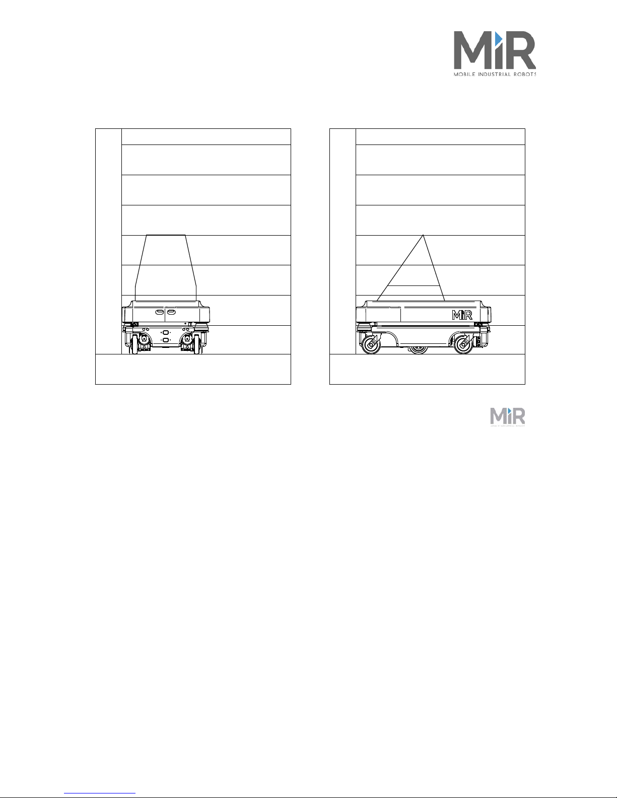
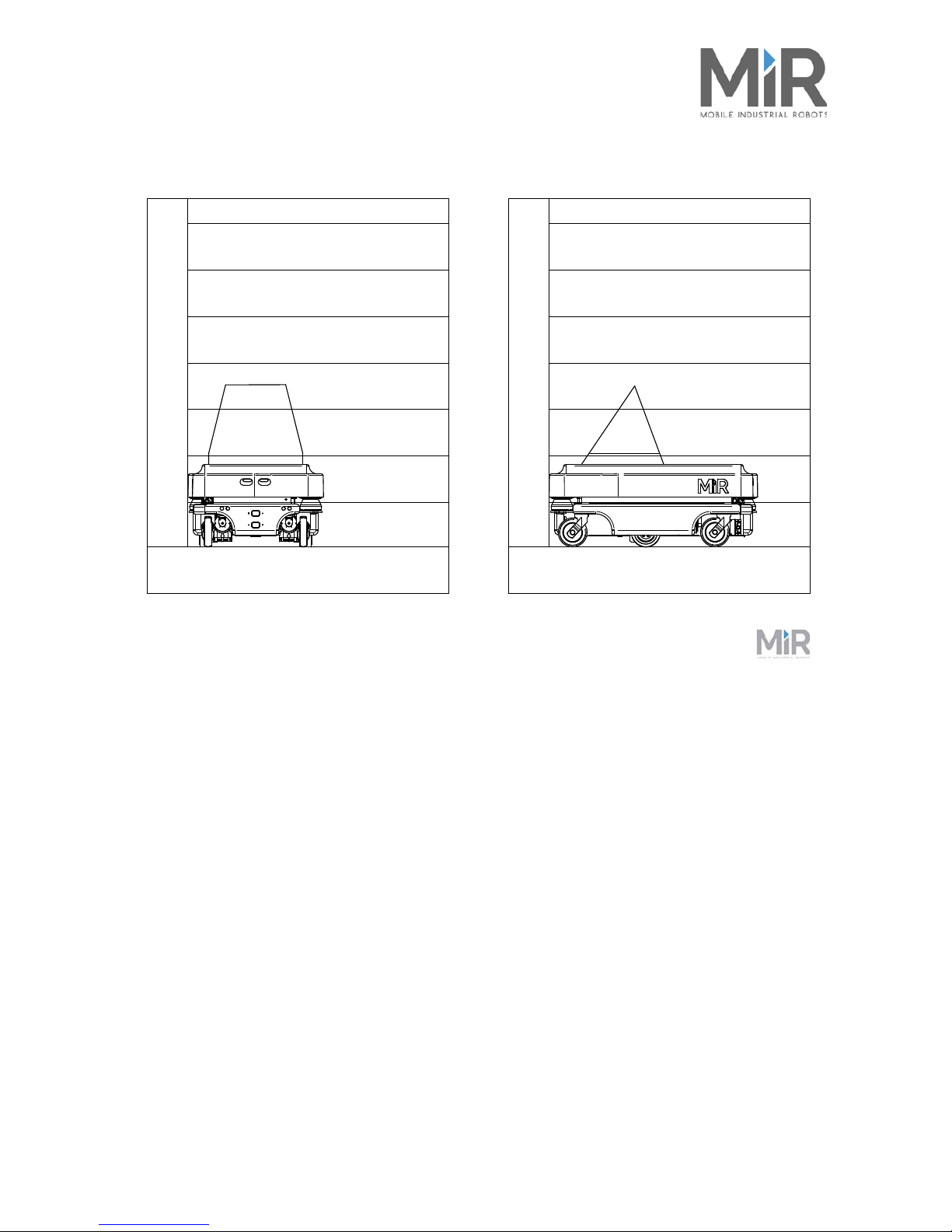
A Payload specifications
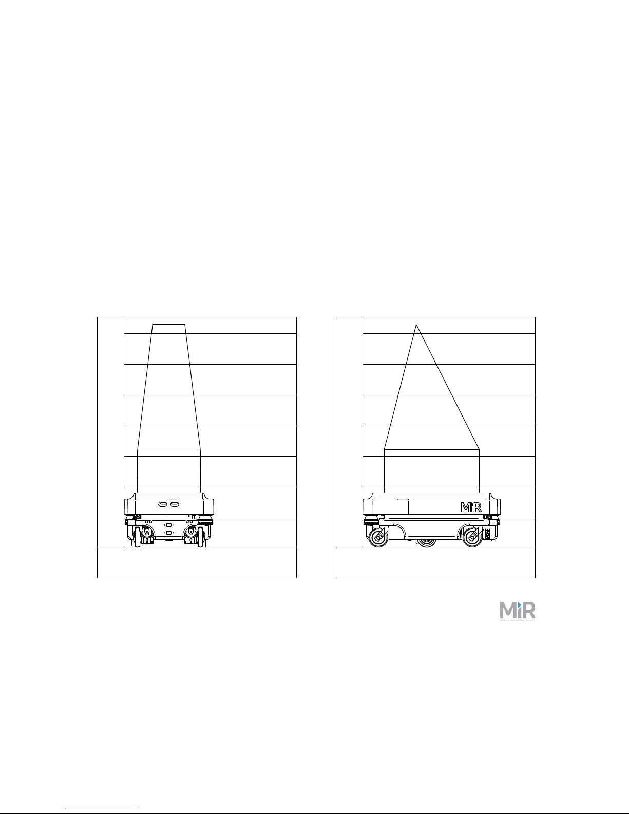
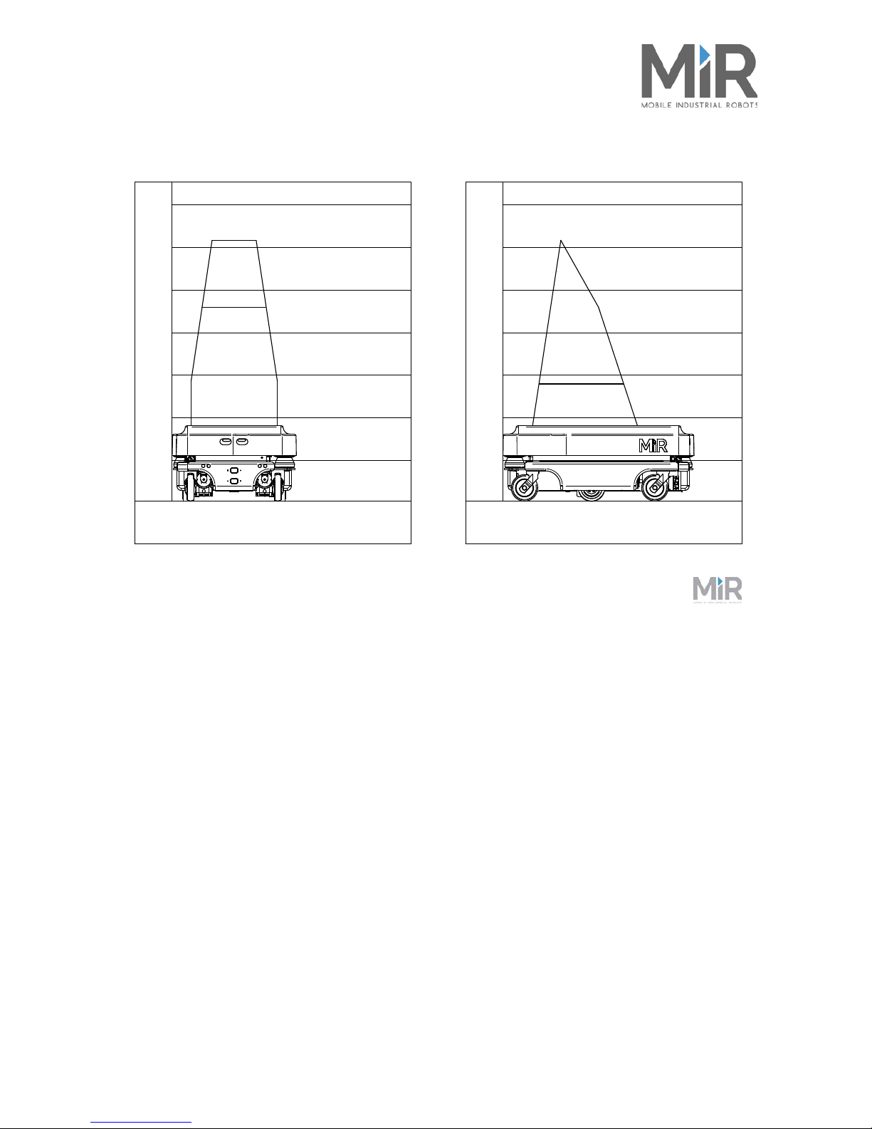
The following drawings illustrate the center of mass (CoM) specifications for safe operation at
different payloads.
The specifications apply to payloads of:
• 25 kg
• 50 kg
• 75 kg
• 100 kg
200
400
800
600
1000
1200
1400
2000
400
600
200
400
8
0
0
600
1000
1
2
00
1
4
00
2
00
0
40
0
600
Units: mm
25kg payload
800600400200 1000800600400200 1000
Page 33
•
•
•
•
•
•
Payload specifications
MiR100™ User Guide, Robot Interface 2.0, 11/2017 v.1.0 31
200
400
800
600
1000
1200
1400
2000
400
600
200
400
8
0
0
600
1000
1
2
00
1
4
00
2
00
0
40
0
600
Units: mm
50kg payload
800600400200 1000800600400200 1000
Page 34
•
•
•
•
•
•
Payload specifications
MiR100™ User Guide, Robot Interface 2.0, 11/2017 v.1.0 32
200
400
800
600
1000
1200
1400
2000
400
600
200
400
8
0
0
600
1000
1
2
00
1
4
00
2
00
0
40
0
600
Units: mm
75kg payload
800600400200 1000800600400200 1000
Page 35
•
•
•
•
•
•
Payload specifications
MiR100™ User Guide, Robot Interface 2.0, 11/2017 v.1.0 33
200
400
800
600
1000
1200
1400
2000
400
600
200
400
8
0
0
600
1000
1
2
00
1
4
00
2
00
0
40
0
600
Units: mm
100kg payload
800600400200 1000800600400200 1000
Page 36

•
•
•
•
•
•
MiR100™ User Guide, Robot Interface 2.0, 11/2017 v.1.0 34
• • • • • •
B Declaration of conformity
page 1/1
EU declaration of Conformity
according to the EU Machinery Directive 2006/42/EC, Annex II 1.A
Manufacturer
Mobile Industrial Robots ApS
Person established in the Community
authorized to compile the technical file
Emil Neckelmanns Vej 15 F Flemming Thinggaard
DK-5220 Odense SØ Mobile Industrial Robots ApS
Emil Neckelmanns Vej 15F
DK - 5220 Odense SØ
Description and identification of the machinery
Product MiR100 1.9 - Serial no. 170100001900354 and higher
Commercial name MiR100
Function MiR100: self-propelled vehicle (batte ry)
MiR100 is an automatic vehicle that can transport materials internally with in factories, warehouses, hospitals and a
host of other industrial locations.
The user provides the destination of product delivery via a web in terface. MiR100 can be set up to run a fixed route
(Route), be called on demand (Taxi), or perform a more special ope ration (Mission).
MiR100 has a map that can be programmed the first time the vehicle is use d. While operating, the MiR100
automatically avoids obstacles (people, furniture) that are no t mapped.
MiR100’s internal map contains specific locations (office, hall, John’s room etc.) which can be used for logistical
planning.
Each vehicle has its own network.
The vehicle is controlled from a website (HTML5), w hich is accessed via a browser on a PC, tablet or smartphone.
It is expressly declared that the machinery fulfills all relevant provisions of the following EU Directives or
Regulations:
2006/42/EC Directive 2006/42/EC of the European Parliament and of the Council of 17 May 2006 on machinery, and
amending Directive 95/16/EC (recast) (1)
Reference to the harmonized standards used, as referred to in Article 7 (2):
EN 60204-1:2006/A1:2009 Safety of machinery – Electrical equipment of machines – Part 1: General requirements
EN ISO 12100:2010-11 Safety of machinery – General principles for design – Risk assessment and risk reduction (ISO
12100:2010)
EN ISO 13849-1:2015 Safety of machinery – Safety related parts of control systems – Part 1: General principles for design
(ISO 13849-1:2015)
EN ISO 13849-2:2012 Safety of machinery – Safety related parts of control systems – Part 2: Validation (ISO 13849-
2:2012)
EN ISO 13850:2015 Safety of machinery – Emergency stop function – Principles for design (ISO 13850:2015)
EN 60204-1:2006-6 Safety of machinery – Electrical equipment of machines – Part 1: General requirements
EN 1175-1:1998+A1:2010 Safety of industrial trucks – Electrical requirements – Part 1: General requirements for battery
powered trucks
Reference of the other technical standards and specifications used:
EN 1525:1997-09 Safety of industrial trucks – Driverless trucks and their systems
Odense SØ, 01 June 2017
Signature
Niels Jul Jacobsen
CTO
ignatur
e
iels Jul Ja
cobssss
en
Page 37

•
•
•
•
•
•
Declaration of conformity
MiR100™ User Guide, Robot Interface 2.0, 11/2017 v.1.0 35
Page 38

•
•
•
•
•
•
MiR100™ User Guide, Robot Interface 2.0, 11/2017 v.1.0 36
• • • • • •
C Neutrik connector
Figure C.1. Neutrik FC4 FDL1-B
PIN number Signal name Max. current Remarks
1 Battery voltage 3A Always on
2 Battery voltage 3A Starts with the robot
3 Battery voltage 10A Stops by emergency stop
4 GND 10A Ground
Page 39

•
•
•
•
•
•
Neutrik connector
MiR100™ User Guide, Robot Interface 2.0, 11/2017 v.1.0 37
 Loading...