

Page 1

MIPS® Malta
TM
Developer’s Kit - Getting
Started with Windows® Embedded CE
Document Number: MD00141
Revision 6.03
December 20, 2009
Copyright © 2007, 2009 MIPS Technologies Inc. All rights reserved.
MIPS Technologies, Inc.
955 East Arques Avenue
Sunnyvale, CA 94085-4521
Page 2

Contents
Section 1: Overview................................................................................................................................ 4
1.1: How to Get Started ...................................................................................................................................... 4
1.2: Target Hardware.......................................................................................................................................... 4
1.3: Host Development PC Requirements.......................................................................................................... 4
1.4: Required Software Tools ............................................................................................................................. 5
Section 2: Target Hardware Setup ........................................................................................................ 6
2.1: Jumper Settings........................................................................................................................................... 7
2.2: DIP Switch Settings ..................................................................................................................................... 7
2.3: Installing PCI Cards..................................................................................................................................... 7
2.3.1: Network Cards ............................................................................................................................. 7
Section 3: Host Development PC Setup ............................................................................................... 8
3.1: Installing the Windows Embedded CE Tools............................................................................................... 8
3.2: Installing the MIPS Malta BSP..................................................................................................................... 8
3.3: Verify the Windows Embedded CE Tool Installation ................................................................................... 8
Section 4: Target Software Setup ....................................................................................................... 10
4.1: Installing the Windows Embedded CE Boot loader ................................................................................... 10
4.1.1: Binary installation: BOOT_xxx.fl ................................................................................................ 10
4.1.2: Binary installation: BOOT_xxx.bin ............................................................................................. 12
4.1.3: Binary installation: BOOT_xxx.sre ............................................................................................. 14
4.2: Configuring the Windows Embedded CE Boot loader ............................................................................... 17
Section 5: Host/Target Connectivity ................................................................................................... 19
Section 6: Support................................................................................................................................ 21
Section 7: Revision History ................................................................................................................. 22
MIPS® Malta
TM
Developer’s Kit - Getting Started with Windows® Embedded CE, Revision 6.03 2
Copyright © 2007, 2009 MIPS Technologies Inc. All rights reserved.
Page 3

3 MIPS® Malta
Copyright © 2007, 2009 MIPS Technologies Inc. All rights reserved.
TM
Developer’s Kit - Getting Started with Windows® Embedded CE, Revision 6.03
Page 4

1 Overview
This document describes how to get started with Microsoft® Windows® Embedded CE version 6.0 operating system
on the MIPS® Malta™ development platform.
1.1 How to Get Started
New users of the Malta development platform are recommended to read and follow the guidelines in the document,
"Malta Developers Kit Getting Started" (MD00051), delivered along with the Malta board, to understand the basic
Malta hardware in operation and then continue with the guidelines in this document to proceed with setting up a Windows Embedded CE development environment on Malta.
1.2 Target Hardware
The basic Malta hardware, as delivered, consists of the Malta motherboard and its daughter board, which carries a
suitable CPU (MIPS32-4Kc/4KEc/4KSc/24Kc/24Kf/34K/1004K or MIPS64-5Kc/5Kf/20Kc/25Kf) and System Controller (Galileo GT64120, MIPS Bonito64, or MIPS SOCit
32 MB PC100 SDRAM (64 MB is recommended). This release supports the L2 cache.
In addition to the basic Malta hardware, you will need:
™). The daughter board must be equipped with a minimum
• Suitable standard ATX cabinet with power supply. For a power supply with standby capabilities, a minimum current of 720 mA is required (1A/1.5A peak recommended) for the 5V standby voltage.
• Windows Embedded CE compatible Video PCI card (the MIPS Malta BSP defaults to the ATI RageXL)
• Optional Windows Embedded CE compatible Audio PCI card (the MIPS Malta BSP defaults to the Ensoniq
ES1371 PDD)
• Optional NE2000 compatible Ethernet PCI card, when booting Windows Embedded CE stand alone applications.
(Nno KITL/VMINI transport)
• PS/2 Keyboard and Mouse
• VGA monitor
• Ethernet cables
• Parallel port cable for downloading Windows Embedded CE 6.0 boot loader
1.3 Host Development PC Requirements
Please see details on the Microsoft product, Windows Embedded CE 6.0, for the current list of requirements for the
host PC. Recent requirements included:
• 600 MHz Pentium (1 GHz recommended) processor
MIPS® Malta
TM
Developer’s Kit - Getting Started with Windows® Embedded CE, Revision 6.03 4
Copyright © 2007, 2009 MIPS Technologies Inc. All rights reserved.
Page 5

• 192 MB RAM (256 MB recommended)
• Without MSDN, an aggragate of 3 GB, 3.8 or 4.8 GB with an MSDN installation
• CD-ROM or DVD-ROM drive is not required
• Graphics display of 800x600 at 256 colors; 1024x768 16-bit color recommended
• Microsoft Mouse or compatible pointing device
1.4 Required Software Tools
To start Windows Embedded CE development on Malta, you will need following software:
• Microsoft Windows Embedded CE version 6.0. This tool package contains Platform Builder 6.0, all the binary
Windows Embedded CE 6.0 OS kernels and system libraries, and the Microsoft® Visual C++® 2005.
NOTE: To get more information and to submit an order for the package, you may go to Microsoft’s website to
Products and Related Technologies, to Develop Tools, to Windows Embedded.
• MIPS Malta Development Platform BSP (release 06.00.00 or higher) for the Windows Embedded CE 6.0 operating system
NOTE: Please send an email request to "support@mips.com" with subject "Request for MIPS Malta Windows
Embedded CE 6.0 BSP".
• A terminal emulation program for communicating with the Target Malta board via its Debug Serial port. We do
not recommend using HyperTerm, as it can be confusing when used in this system to determine the order of lines
displayed from the target. Alternatives include Tera Term, which is a free terminal emulator (see The Tera Term
Home Page) and Procomm Plus32, which can be purchased from Datastorm Technologies.
5 MIPS® Malta
Copyright © 2007, 2009 MIPS Technologies Inc. All rights reserved.
TM
Developer’s Kit - Getting Started with Windows® Embedded CE, Revision 6.03
Page 6
2 Target Hardware Setup
12345678910
1 2 3 4 5 6 7 8
3V
1 2 4
5 6 7 83
1 2 43
U42
J17
J15
J16
J14
J13
J12
J2
J4
J3
J8
J7
J5
J6
JP4
JP2
J10
J22
J20
J19 J18
J21
J9
J1
JP1
JP3
S5
S2
D28
ON/NMI
RESET
RST
STBY
5V
3V3
ATX ON
FPGA
TX
SPD100
J31
PCI SLOT#1
PCI SLOT#2
PCI SLOT#3
PCI SLOT#4
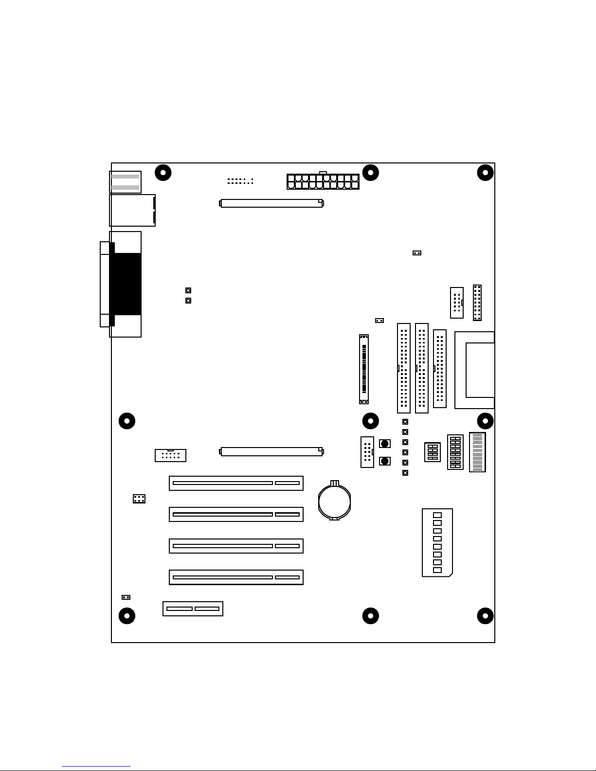
The diagram in Figure 1 shows the layout of the Malta board.
Figure 1 Location of Essential Features of Malta Board
MIPS® Malta
TM
Developer’s Kit - Getting Started with Windows® Embedded CE, Revision 6.03 6
Copyright © 2007, 2009 MIPS Technologies Inc. All rights reserved.
Page 7

For Windows Embedded CE on Malta, following locations are important to notice:
• ’JP4’ (left side): jumpers to control the PCI clock frequency
• ’S5-0’ (right side): dip switch "PROG" controls programming of on-board flash via the parallel port
• ’S5-1’ (right side): dip switch "BIGEND" controls endianness and must be set ’OFF’ = ’little endian’, as the
Windows Embedded CE operating system is available (compiled) for ’little endian’ only
• ’J12’-’J15’: PCI slots 1-4
2.1 Jumper Settings
By default, no jumpers are fitted on the Malta board.
NOTE: When using a Malta daughter board with a core bus speed slower than the default PCI-clock of 33 MHz, the
PCI-clock speed must be adjusted via jumper block JP4 to be the same or slower than the core bus speed. See "Malta
User’s Manual" (MD00048) Table 23 "Jumpers" for a list of available PCI-clock speeds and jumper combinations.
2.2 DIP Switch Settings
The dip switch, S5-1 BIGEND, must be set to OFF to set endianness = little. (The Windows Embedded CE operating
system is always compiled for little endianness.)
2.3 Installing PCI Cards
PCI cards may be installed in any slot on the Target Malta board, but some slots share interrupt lines with other
devices on the PCI bus. PCI card placement may affect interrupt priority and latency.
PCI devices map to the following interrupts:
• PCI slot 1 maps to PCI INTA which is steered to IRQ5 on the PIIX4E South Bridge Interrupt Controller
• PCI slot 2 and the on-board AMD Ethernet Controller (AM79C973) map to PCI INTB which is steered to IRQ10
on the PIIX4E South Bridge Interrupt Controller
• PCI slot 3 and the on-board Crystal Audio Controller (CS4281) map to PCI INTC which is steered to IRQ11 on
the PIIX4E South Bridge Interrupt Controller
• PCI slot 4 and the on-board PIIX4E USB Host Controller map to PCI INTD which is steered to IRQ9 on the
PIIX4E South Bridge Interrupt Controller
2.3.1 Network Cards
When using the Malta board with Platform Builder, the Malta on-board Ethernet Controller is supported by the shared
Ethernet driver of the MIPS Malta BSP, providing download and debug network traffic and application network traffic as well. However, the shared Ethernet driver cannot be used for stand alone Windows Embedded CE applications,
when booting Windows Embedded CE images in non-debug mode. Therefore, to obtain network access for stand
7 MIPS® Malta
Copyright © 2007, 2009 MIPS Technologies Inc. All rights reserved.
TM
Developer’s Kit - Getting Started with Windows® Embedded CE, Revision 6.03
Page 8

alone applications, an NE2000-compatible PCI Ethernet Controller may be installed in an available PCI slot. See the
Windows Embedded CE documentation for a list of supported PCI Ethernet Controllers.
3 Host Development PC Setup
3.1 Installing the Windows Embedded CE Tools
Windows Embedded CE 6.0 is delivered in conjuction with Microsoft Visual Studio 2005. To install, you will first
install the Microsoft Visual Studio Suite, and then install Windows Embedded CE 6.0. Follow the installation instructions for Microsoft Visual Studio 2005 first, which will lead you through two discs.
During installation configuration of Windows Embedded CE 6.0 , you will be asked to select which CPUs will be
supported. Please select all of the following:
• MIPSII
• MIPSII_FP
• MIPSIV
• MIPSIV_FP
3.2 Installing the MIPS Malta BSP
You can download the MIPS Malta BSP from the MIPS Technologies web site: http://www.mips.com/products/softwaretools/system_software/Windows_CE_BSP.php.
The download includes:
• This document (MD00141 – Malta
6.0)
• Release Notes, in readme.txt
• Microsoft Installation package
The MIPS Malta BSP source, a Platform Builder CEC description file, and a readme.txt file detailing use of the BSP
with the Malta development board, are located in the Microsoft Installation package.
Double-click on the MSI file to begin installing the MIPS Malta BSP and follow the Package Wizard instructions to
complete the installation.
TM
Developer’s Kit – Getting Started with Windows Embedded Embedded CE
3.3 Verify the Windows Embedded CE Tool Installation
Now everything should be installed on the Host Development PC and the Windows Embedded CE development environment for MIPS Malta BSP should be ready. The installation should be verified by building a Windows Embedded
MIPS® Malta
TM
Developer’s Kit - Getting Started with Windows® Embedded CE, Revision 6.03 8
Copyright © 2007, 2009 MIPS Technologies Inc. All rights reserved.
Page 9

CE sample image. The following example describes how to build a sample image with the ready to use sample platform, "Internet Appliance", and built for a "MIPSII" kernel, which is compliant with all supported MIPS CPU cards
on Malta.
Lauch Start-> All Programs-> Microsoft Visual Studio 2005-> Microsoft Visual Studio 2005, and execute the following steps:
1. Enter File -> New-> Project
2. Select “Platform Builder for CE 6.0” in the left pane, and “OS Design” in the right. Enter a name for your new
design, and press OK.
3. Press Next.
4. Select “MIPS Malta: MIPSII”, and press Next.
5. Select Industrial Device and press Next.
6. Select Internet Appliance and press Next.
7. Press Finish,
8. The pop-up “Catalog Item Notification” is a standard Microsoft security warning; press Acknowledge.
9. Select “Build Solution” from the Build pull-down menu to build the Windows Embedded CE sample image and
await build completion. For those with prior experience with Microsoft CE products, avoid the “Advanced Build
Commands” -> “Build and Sysgen” option; it rebuilds code for which libraries are shipped that you do not need
to rebuild.
Verify that the image builds to completion with no errors.
You can change build options by selecting the Project -> Properties pull-down. In the pop-up window, select Configuration Properities -> Build Options. For example, if you are doing a release build, you may still want to enable the
Debugger.
NOTE: For Step 9, a potential risk exists, especially when building big images like debug images, to get build errors
like "Error: Too much data space used by DLLs in MODULES section....". The reason is that more static memory
than the default (min. 32 MB device) is required and must be assigned by setting a predefined environment variable
"IMGRAM64" to "1" (min. 64 MB device). This Build Option can be found on the same pop-up window as described
in the previous paragraph – it is labeled “Run-time image can be larger than 32 MB (IMGRAM64=1)”.
Once you have done a build, you can modify the build options, or the BSP code, and need not recompile the entire
Windows Embedded CE space. You can rebuild just the BSP by going into the Solution Explorer, expand your solution name, and the top of the Windows Embedded CE tree, expand PLATFORM, and you will see “MIPS_MALTA”.
If you right-click on MIPS_MALTA, you can do a build (or re-build) just from there, for a great savings of time. Note
this will not work if you have not already completed a build, or if you have changed anything outside the scope of the
BSP.
9 MIPS® Malta
Copyright © 2007, 2009 MIPS Technologies Inc. All rights reserved.
TM
Developer’s Kit - Getting Started with Windows® Embedded CE, Revision 6.03
Page 10

4 Target Software Setup
4.1 Installing the Windows Embedded CE Boot loader
After the MIPS Malta BSP has been installed into Platform Builder, The Windows Embedded CE boot loader binary
files and a readme.txt file detailing the installation of the boot loader, is located in the following directory:
%_WINCEROOT%\PLATFORM\MIPS_MALTA\bin
This directory contains the boot loader images for the Target Malta board in Motorola S-record format, Yamon BIN
format and MIPS Malta 1284 Flash Download format. There are two types of BOOT images delivered with the MIPS
Malta BSP. One supports at least 32 MB of RAM, and the other supports at least 64 MB of RAM. Please choose the
appropriate image for your application.
The MIPS Malta boot loader for Windows Embedded CE 6.0 is not backwards-compatible with OS images built on
an older version of Windows CE.
4.1.1 Binary installation: BOOT_xxx.fl
The MIPS Malta Flash Download binary file, BOOT_xxx.fl, may be downloaded via the Parallel port to the Target
Malta board.
Before you begin, you must attach a Parallel port cable between the Target Malta board and the Host Development
PC. You should also have a serial cable attached between the Debug Serial port (TTY0) on the Target Malta board and
the Host Development PC, and your preferred terminal emulator connected directly to the COM port where the cable
is connected on the Host Development PC.
Having attached all cables to the Target Malta board, you should now power up the Malta board and a YAMON
prompt, like the example below, should be displayed in your terminal emulator.
YAMON ROM Monitor, Revision 02.13.
Copyright (c) 1999-2006 MIPS Technologies, Inc. - All Rights Reserved.
For a list of available commands, type ’help’.
Compilation time = Dec 7 2006 19:22:35
Board type/revision = 0x02 (Malta) / 0x00
Core board type/revision = 0x0a (Core24K) / 0x00
System controller/revision = MIPS SOC-it 101 OCP / 1.3 SDR-FW-2:1
FPGA revision = 0x0001
MAC address = 00.d0.a0.00.01.4e
Board S/N = 0000000086
PCI bus frequency = 33.33 MHz
Processor Company ID/options = 0x01 (MIPS Technologies, Inc.) / 0x00
Processor ID/revision = 0x93 (MIPS 24Kc) / 0x64
Endianness = Little
CPU/Bus frequency = 266 MHz / 133 MHz
Flash memory size = 4 MByte
SDRAM size = 128 MByte
First free SDRAM address = 0x800b7360
MIPS® Malta
TM
Developer’s Kit - Getting Started with Windows® Embedded CE, Revision 6.03 10
Copyright © 2007, 2009 MIPS Technologies Inc. All rights reserved.
Page 11

YAMON>
Please verify from the prompt that Endianness = Little. If not, set Malta DIP-switch S5-2=OFF.
1. Enable Flash Download mode by setting DIP switch S5-0 (PROG) to ON. The Alpha display should read:
Flash DL
2. On the Host Development PC side enter the BIN directory in the MIPS Malta BSP. From the command line, execute the following command:
For the 32 Mbyte image:
%_WINCEROOT%\PLATFORM\Mips_malta\Bin> ..\Scripts\go_32MB.bat
For the 64 Mbyte image:
%_WINCEROOT%\PLATFORM\Mips_malta\Bin> ..\Scripts\go_64MB.bat
3. When completed, the Alpha display should read:
FINISHED
4. Disable Flash Download mode by setting DIP switch S5-0 (PROG) to ’OFF’. A YAMON prompt like the example below, should be displayed on the terminal emulator.
YAMON ROM Monitor, Revision 02.13.
Copyright (c) 1999-2003 MIPS Technologies, Inc. - All Rights Reserved.
For a list of available commands, type ’help’.
Compilation time = Aug 12 2002 11:22:06
Board type/revision = 0x02 (Malta) / 0x00
Core board type/revision = 0x03 (Core20K) / 0x02
System controller/revision = Bonito64 / 1-10f-e2 02/06/25/10:49
FPGA revision = 0x0001
MAC address = 00.d0.a0.00.00.91
Board S/N = 0000000024
PCI bus frequency = 33.33 MHz
Processor Company ID/options = 0x01 (MIPS Technologies, Inc.) / 0x04
Processor ID/revision = 0x82 (MIPS 20Kc) / 0x60
Endianness = Little
CPU/Bus frequency = 500 MHz / 100 MHz
Flash memory size = 4 MByte
SDRAM size = 64 MByte
First free SDRAM address = 0x800adc80^
YAMON>
5. Setup YAMON to execute the boot loader program after reset:
YAMON> set start ’go be100000’
6. Now, reset the Target Malta board (either YAMON-cmd: ’reset’ or press front reset button)
The boot loader will come up with the following display on the Debug Serial port:
11 MIPS® Malta
Copyright © 2007, 2009 MIPS Technologies Inc. All rights reserved.
TM
Developer’s Kit - Getting Started with Windows® Embedded CE, Revision 6.03
Page 12

Microsoft Windows CE Ethernet Bootloader Common Library Version 6.0 Built
May 29 2007 at 13:21:28
Microsoft Windows CE Ethernet Bootloader Version 6.0 for MIPS Malta Built
May 29 2007 at 15:38:47
Processor Info: Company MIPS Technologies Inc., Implementation 20Kc.
L1 ICache Info: SetsPerWay 256, NumWays 4, LineSize 32, Size 32768.
L1 DCache Info: SetsPerWay 256, NumWays 4, LineSize 32, Size 32768.
TLB Entries: 48.
CPU Frequency: 267 MHz
SDRAM Size: 64 MBytes
System ready!
Preparing for download...
INFO: Predownload....
INFO: No boot configuration found at 0x9e180000
Hit space to enter configuration menu 5...
Hit space to enter configuration menu 4...
...
You have now completed installation of the Windows Embedded CE boot loader.
4.1.2 Binary installation: BOOT_xxx.bin
The YAMON binary file, BOOT_xxx.bin, may be downloaded via the Ethernet port (TFTP download) to the Target
Malta board.
Before you begin, you must copy the Windows Embedded CE 6.0 boot loader image, BOOT_xxx.bin, to your TFTP
host’s TFTP boot directory. Attach an Ethernet port cable to the Target Malta board so it resides on a network that can
access the TFTP host. You should also have a serial cable attached between the Debug Serial port (TTY0) on the Target Malta board and the Host Development PC, and your preferred terminal emulator connected directly to the COM
port where the cable is connected on the Host Development PC.
Having attached all cables to the Target Malta board, you should now power up the Malta board and a YAMON
prompt like the example below should be displayed in your terminal emulator.
YAMON ROM Monitor, Revision 02.13.
Copyright (c) 1999-2003 MIPS Technologies, Inc. - All Rights Reserved.
For a list of available commands, type ’help’.
Compilation time = Aug 12 2002 11:22:06
Board type/revision = 0x02 (Malta) / 0x00
Core board type/revision = 0x03 (Core20K) / 0x02
System controller/revision = Bonito64 / 1-10f-e2 02/06/25/10:49
FPGA revision = 0x0001
MAC address = 00.d0.a0.00.00.91
Board S/N = 0000000024
PCI bus frequency = 33.33 MHz
Processor Company ID/options = 0x01 (MIPS Technologies, Inc.) / 0x04
Processor ID/revision = 0x82 (MIPS 20Kc) / 0x60
Endianness = Little
CPU/Bus frequency = 500 MHz / 100 MHz
MIPS® Malta
TM
Developer’s Kit - Getting Started with Windows® Embedded CE, Revision 6.03 12
Copyright © 2007, 2009 MIPS Technologies Inc. All rights reserved.
Page 13

Flash memory size = 4 MByte
SDRAM size = 64 MByte
First free SDRAM address = 0x800adc80
YAMON>
Please verify from the prompt, that ’Endianness = Little’. If not, set Malta DIP-switch S5-2=OFF.
1. Get a reserved IP-address from your network administrator for YAMON’s IP-stack.
Setup YAMON IP-address:
YAMON> set ipaddr 192.168.201.52
Setup YAMON subnetmask:
YAMON> set subnetmask 255.255.255.0
When needed, setup YAMON IP-gateway (ask your network administrator):
YAMON> set gateway 192.168.201.254
Setup TFTP-hostserver:
YAMON> set bootserver 192.168.201.197
Now you have completed the YAMON network setup and are ready to start the download and install procedure of
the Windows Embedded CE 6.0 boot loader image.
2. Initially, clear 128 KB of user FLASH area:
YAMON> erase be100000 20000
3. Download the boot loader image via TFTP from the TFTP host into the Target Malta board RAM:
YAMON> fread tftp://<tftphost>/BOOT_xxx.bin 80100000
About to binary read tftp://<tftphost>/BOOT_xxx.bin
Press Ctrl-C to break
Start = 0x80100000, range = (0x80100000,0x80119FC0), format = BIN
4. Flush the downloaded image to memory:
YAMON> flush
5. Copy the boot loader image from RAM to user FLASH:
YAMON> copy 80100000 be100000 20000
6. Configure YAMON to execute the boot loader program after reset:
13 MIPS® Malta
Copyright © 2007, 2009 MIPS Technologies Inc. All rights reserved.
TM
Developer’s Kit - Getting Started with Windows® Embedded CE, Revision 6.03
Page 14

YAMON> set start ’go be100000’
7. Now, reset the Target Malta board (either YAMON-cmd: ’reset’ or press front reset button)
The boot loader will come up with the following display on the Debug Serial port:
Microsoft Windows CE Ethernet Bootloader Common Library Version 1.0 Built
May 29 2007 at 13:21:28
Microsoft Windows CE Ethernet Bootloader Version 5.0 for MIPS Malta Built
May 29 2007 at 15:38:47
Processor Info: Company MIPS Technologies Inc., Implementation 20Kc.
L1 ICache Info: SetsPerWay 256, NumWays 4, LineSize 32, Size 32768.
L1 DCache Info: SetsPerWay 256, NumWays 4, LineSize 32, Size 32768.
TLB Entries: 48.
CPU Frequency: 267 MHz
SDRAM Size: 64 MBytes
System ready!
Preparing for download...
INFO: Predownload....
INFO: No boot configuration found at 0x9e180000
Hit space to enter configuration menu 5...
Hit space to enter configuration menu 4...
...
You have now completed installation of the Windows Embedded CE boot loader.
4.1.3 Binary installation: BOOT_xxx.sre
The Motorola S-record file, BOOT_xxx.sre, may be downloaded either via the Debug Serial port or Ethernet port
(TFTP download) to the Target Malta board.
Before you begin, you must copy the Windows Embedded CE 6.0 boot loader image, BOOT_xxx.sre, to your terminal emulator’s download directory or your TFTP host’s TFTP boot directory, depending on your preferred download
type. If you select TFTP download, attach an Ethernet port cable to the Target Malta board so it resides on a network
that can access the TFTP host. You should also have a serial cable attached between the Debug Serial port (TTY0) on
the Target Malta board and the Host Development PC, and your preferred terminal emulator connected directly to the
COM port where the cable is connected on the Host Development PC.
Having attached all cables to the Target Malta board, you should now power up the Malta board and a YAMON
prompt like the example below should be displayed in your terminal emulator.
YAMON ROM Monitor, Revision 02.13.
Copyright (c) 1999-2003 MIPS Technologies, Inc. - All Rights Reserved.
For a list of available commands, type ’help’.
Compilation time = Aug 12 2002 11:22:06
Board type/revision = 0x02 (Malta) / 0x00
Core board type/revision = 0x03 (Core20K) / 0x02
System controller/revision = Bonito64 / 1-10f-e2 02/06/25/10:49
MIPS® Malta
TM
Developer’s Kit - Getting Started with Windows® Embedded CE, Revision 6.03 14
Copyright © 2007, 2009 MIPS Technologies Inc. All rights reserved.
Page 15

FPGA revision = 0x0001
MAC address = 00.d0.a0.00.00.91
Board S/N = 0000000024
PCI bus frequency = 33.33 MHz
Processor Company ID/options = 0x01 (MIPS Technologies, Inc.) / 0x04
Processor ID/revision = 0x82 (MIPS 20Kc) / 0x60
Endianness = Little
CPU/Bus frequency = 500 MHz / 100 MHz
Flash memory size = 4 MByte
SDRAM size = 64 MByte
First free SDRAM address = 0x800adc80
YAMON>
Please verify from the prompt, that Endianness = Little. In case not, set Malta DIP-switch S5-2=OFF.
1. If you are going to download via TFTP, get a reserved IP-address from your network administrator for YAMON’s
IP-stack.
Setup YAMON IP-address:
YAMON> set ipaddr 192.168.201.52
Setup YAMON subnetmask:
YAMON> set subnetmask 255.255.255.0
When needed, setup YAMON IP-gateway (ask your network administrator):
YAMON> set gateway 192.168.201.254
Setup TFTP-hostserver:
YAMON> set bootserver 192.168.201.197
Now you have completed the YAMON network setup and are ready to start the download and install procedure of
the Windows Embedded CE 6.0 boot loader image.
2. Initially, clear 128 KB of user FLASH area:
YAMON> erase be100000 20000
3. Download the boot loader image via Serial/TFTP from the Host Development PC/TFTP host into the Target
Malta board RAM:
Serial download:
YAMON> load asc://tty0
About to load asc://tty0
Press Ctrl-C to break
Start dump from terminal program
NOTE: Now download/dump the BOOT_xxx.sre file from your terminal emulator. If you are using TeraTerm,
select the pulldown menu option File -> Send File..., and select the file to send. With Hyperterminal, you must
15 MIPS® Malta
Copyright © 2007, 2009 MIPS Technologies Inc. All rights reserved.
TM
Developer’s Kit - Getting Started with Windows® Embedded CE, Revision 6.03
Page 16

enter the menu Transfer-> SendTextFile
TFTP download:
YAMON> load tftp://<tftphost>/BOOT_xxx.sre
About to load tftp://<tftphost>/BOOT_xxx.sre
Press Ctrl-C to break
The load message for the 32 MB image:
Start = 0x81F80004, range = (0x81F80000,0x81F99FC0), format = SREC
The load message for the 64 MB image:
Start = 0x83F80004, range = (0x83F80000,0x83F99FC0), format = SREC
4. Flush the downloaded image to memory:
YAMON> flush
5. Copy the boot loader image from RAM to user FLASH:
The 32 MB image:
YAMON> copy 81F80000 be100000 20000
The 64 MB image:
YAMON> copy 83F80000 be100000 20000
6. Configure YAMON to execute the boot loader program after reset:
YAMON> set start ’go be100000’
7. Now, reset the Target Malta board (either YAMON-cmd: ’reset’ or press front reset button)
The boot loader will come up with the following display on the Debug Serial port:
Microsoft Windows CE Ethernet Bootloader Common Library Version 1.0 Built
May 29 2007 at 13:21:28
Microsoft Windows CE Ethernet Bootloader Version 6.0 for MIPS Malta Built
May 29 2007 at 15:38:47
Processor Info: Company MIPS Technologies Inc., Implementation 20Kc.
L1 ICache Info: SetsPerWay 256, NumWays 4, LineSize 32, Size 32768.
L1 DCache Info: SetsPerWay 256, NumWays 4, LineSize 32, Size 32768.
TLB Entries: 48.
CPU Frequency: 267 MHz
SDRAM Size: 64 MBytes
System ready!
MIPS® Malta
TM
Developer’s Kit - Getting Started with Windows® Embedded CE, Revision 6.03 16
Copyright © 2007, 2009 MIPS Technologies Inc. All rights reserved.
Page 17

Preparing for download...
INFO: Predownload....
INFO: No boot configuration found at 0x9e180000
Hit space to enter configuration menu 5...
Hit space to enter configuration menu 4...
...
You have now completed installation of the Windows Embedded CE boot loader.
4.2 Configuring the Windows Embedded CE Boot loader
After installation completion, the Windows Embedded CE 6.0 boot loader must be configured to communicate with
the Host Development PC. During boot loader initialization, the following messages will be displayed on the terminal
emulator:
Hit space to enter configuration menu 5...
Hit space to enter configuration menu 4...
Hit space to enter configuration menu 3...
Hit space to enter configuration menu 2...
...
Hit the spacebar within the terminal emulator window and navigate the boot loader menus to setup the Boot/Debug
device and Network settings. The top level menu options are as follows:
----------------------------------------------------------
Main Menu
----------------------------------------------------------
[1] Show Current Settings
[2] Set Device Id
[3] Select Boot Device
[4] Select Debug Device
[5] Network Settings
[6] Save Settings
[0] Exit and Continue
When finished, save your settings and exit. The boot loader will continue with its initialization and attempt to connect
with your Host Development PC. You should see something similar to the following output to your terminal emulator:
Am79c973: Wait for link... Link detected
INFO: Boot device uses MAC 00:d0:a0:00:03:1c
INFO: *** Device Name MALTA796 ***
InitDHCP():: Calling ProcessDHCP()
ProcessDHCP()::DHCP_INIT
Got Response from DHCP server, IP address: 172.20.4.2
ProcessDHCP()::DHCP IP Address Resolved as 172.20.4.2, netmask: 255.255.255.224
Lease time: 90060 seconds
Got Response from DHCP server, IP address: 172.20.4.2
No ARP response in 2 seconds, assuming ownership of 172.20.4.2
17 MIPS® Malta
Copyright © 2007, 2009 MIPS Technologies Inc. All rights reserved.
TM
Developer’s Kit - Getting Started with Windows® Embedded CE, Revision 6.03
Page 18

+EbootSendBootmeAndWaitForTftp
Sent BOOTME to 255.255.255.255
Sent BOOTME to 255.255.255.255
Sent BOOTME to 255.255.255.255
Sent BOOTME to 255.255.255.255
Sent BOOTME to 255.255.255.255
Take note of the Device Name, as you will need it later when connecting the Target Malta board to the Host Development PC.
After configuration has completed, the Malta development board provides standard Windows CE SDB development
services, accessible from the Host Development PC via the Platform Builder tools.
MIPS® Malta
TM
Developer’s Kit - Getting Started with Windows® Embedded CE, Revision 6.03 18
Copyright © 2007, 2009 MIPS Technologies Inc. All rights reserved.
Page 19

5 Host/Target Connectivity
After the Host Development PC and Target Malta board have been set up and configured, Windows Embedded CE
6.0 images can be downloaded and debugged using the KITL transport and debug services in Platform Builder. To
verify KITL is working, performing the following steps:
1. Check that the Target Malta Board is still sending "BOOTME" messages. If not, then reset the board and allow
the Windows Embedded CE 6.0 boot loader to reinitialize.
2. On the Host Development PC side, start Microsoft Visual Studio 2005, and open the Sample Project that you
made. Then enter the pull-down menu Target -> Connectivity Options …. Bring the Connectivity Options pop-up
window the foreground.
3. Set Download and Transport both to Ethernet and press ’Settings’ beside the ’Download’ pane to enter the
"Ethernet Download Settings" submenu to select the target device (the target device name should appear in the
selection pane), while the target issues the ’BOOTME’ messages.
4. Finally go to submenu Target->Attach Device to start the download.
5. You should now see the following debug messages on the terminal emulator:
Sent BOOTME to 255.255.255.255
Sent BOOTME to 255.255.255.255
Sent BOOTME to 255.255.255.255
Packet has the following data:
boot.bin[NULL]octet[NULL]
TFTP packet could have 1 name/value pairs
Locked Down Link 1
Src IP 192.168.1.4 Port 03D4 Dest IP 192.168.1.6 Port 0493
Default TFTP block size set to: 512 bytes
There were no options detected in the TFTP
EthDown::TFTPD_OPEN::boot.bin
-EbootSendBootmeAndWaitForTftp
BL_IMAGE_TYPE_BIN
TFTP: Desktop losing ACK, block number = 28628, Ack again
rom_offset=0x0.
ImageStart = 0x80002000, ImageLength = 0x18FE0CC, LaunchAddr = 0x80002004
Completed file(s):
------------------------------------------------------------------------------
[0]: Address=0x80002000 Length=0x18FE0CC Name="" Target=RAM
ROMHDR at Address 80002044h
INFO: Lauch Windows CE .NET by jumping to 0x80002004...
Windows CE Kernel for MIPS Built on May 14 2007 at 16:15:00
+OEMInit
+OALMIPSGetProcessorId()=0x1954C
Processor Info: Company MIPS Technologies Inc., Implementation Unknown.
L1 ICache Info: SetsPerWay 512, NumWays 4, LineSize 32, Size 65536.
19 MIPS® Malta
Copyright © 2007, 2009 MIPS Technologies Inc. All rights reserved.
TM
Developer’s Kit - Getting Started with Windows® Embedded CE, Revision 6.03
Page 20

L1 DCache Info: SetsPerWay 512, NumWays 4, LineSize 32, Size 65536.
TLB Entries: 32.
CPU frequency: 50 MHz
SDRAM size: 128 MBytes
DeviceId................. MALTA871
pArgs->flags............. 0xD
pArgs->devLoc.IfcType.... 5
pArgs->devLoc.LogicalLoc. 0xB00
pArgs->devLoc.PhysicalLoc 0x0
pArgs->devLoc.Pin........ 5
pArgs->ip4address........ 1
pDevice->Name............ s
pDevice->ifcType......... 5
pDevice->id.............. 0x20001022
pDevice->resource........ 1
pDevice->type............ 2
pDevice->pDriver......... 0x81908000
Am79c973: Wait for link...
Link detected
Am79c973: Enable Tx ... KITL: *** Device Name MALTA871 ***
KITL: using sysintr 0x10
-OALKitlEthInit: Getting DCHP address
KITL: DHCP get/renew device IP: 1
-OALKitlEthInit: Got DCHP address
VBridge:: built on [Sep 6 2006] time [19:28:01]
VBridgeInit()...TX = [16384] bytes -- Rx = [16384] bytes
Tx buffer [0xA193EEE0] to [0xA1942EE0].
Rx buffer [0xA1942F00] to [0xA1946F00].
VBridge:: NK add MAC: [0-D0-A0-0-3-67]
Connecting to Desktop
KITL: Connected host IP: 1 Port: 1169
KITL: Leaving polling mode... 0x8192EBC0
Closing Handle of Timer Thread
VBridge:: VB_INITIALIZED returns [1]
VBridge:: RESET_BUFFER received.
VBridge:: built on [Sep 6 2006] time [19:28:01]
VBridgeInit()...TX = [16384] bytes -- Rx = [16384] bytes
Tx buffer [0xA193EEE0] to [0xA1942EE0].
Rx buffer [0xA1942F00] to [0xA1946F00].
VBridge:: Current VMini packet filter = [0xB]
NOTE: Your example configuration has been built with the KITL support, selected before build in the submenu Platform-> Settings and ’Build Options’ with click-select in the ’Enable KITL’.
MIPS® Malta
TM
Developer’s Kit - Getting Started with Windows® Embedded CE, Revision 6.03 20
Copyright © 2007, 2009 MIPS Technologies Inc. All rights reserved.
Page 21

6 Support
MIPS Technologies provides first line support for the Windows Embedded CE on Malta product, through the following channels:
• WWW documentation pages at
answer to any problems or queries you may have. There may be updated versions of the documents available on
the site.
• E-mail hotline. Send an E-mail with your name and company details, plus full details of the hardware and software you have (include revision numbers, serial numbers and as much other information as possible) to:
support@mips.com. Remember to include all details of the problem you are seeing, such as status of LEDs, the
ASCII LED display, what has been output on the Debug Serial port (TTY0), and what has been output on the
Windows CE debug port etc.
http://www.mips.com. This should be your first call when looking for the
21 MIPS® Malta
Copyright © 2007, 2009 MIPS Technologies Inc. All rights reserved.
TM
Developer’s Kit - Getting Started with Windows® Embedded CE, Revision 6.03
Page 22

7 Revision History
Revision Date Description
01.00 2001/06/25 Issued for internal review
01.01 2001/07/04 Comments added after internal review
02.01 2002/05/29 Updated for Windows CE .NET
02.02 2002/06/12 New title
02.03 2002/07/01 Updated after comments from Microsoft
02.04 2002/08/29 Updated for Windows CE .NET 4.10
02.05 2002/09/03 Change bars added and updated to SDT-template 01.07
02.06 2002/11/15 Updated for BSP release 01.04
02.07 2002/11/20 A note about IMGRAM64 env. variable added to par. 2.6
02.08 2003/02/15 Updated for BSP release 01.05
02.09 2003/04/28 Updated with new template
05.00 2004/05/05 Updated for Windows CE .NET 5.0 and MIPS Malta BSP release 05.00
06.00 2007/06/29 Updated for Windows Embedded CE 6.0 and MIPS Malta BSP release 06.00
06.02 2008/03/07 Increased hardware functionality and made bug fixes.
06.03 2009/12/20 Updated for 34K, 1004K, and L2 cache support
MIPS® Malta
TM
Developer’s Kit - Getting Started with Windows® Embedded CE, Revision 6.03 22
Copyright © 2007, 2009 MIPS Technologies Inc. All rights reserved.
Page 23

Copyright © 2007, 2009 MIPS Technologies, Inc. All rights reserved.
Unpublished rights (if any) reserved under the copyright laws of the United States of America and other countries.
This document contains information that is proprietary to MIPS Technologies, Inc. ("MIPS Technologies"). Any copying, reproducing, modifying or use of
this information (in whole or in part) that is not expressly permitted in writing by MIPS Technologies or an authorized third party is strictly prohibited. At a
minimum, this information is protected under unfair competition and copyright laws. Violations thereof may result in criminal penalties and fines.
Any document provided in source format (i.e., in a modifiable form such as in FrameMaker or Microsoft Word format) is subject to use and distribution
restrictions that are independent of and supplemental to any and all confidentiality restrictions. UNDER NO CIRCUMSTANCES MAY A DOCUMENT
PROVIDED IN SOURCE FORMAT BE DISTRIBUTED TO A THIRD PARTY IN SOURCE FORMAT WITHOUT THE EXPRESS WRITTEN
PERMISSION OF MIPS TECHNOLOGIES, INC.
MIPS Technologies reserves the right to change the information contained in this document to improve function, design or otherwise. MIPS Technologies does
not assume any liability arising out of the application or use of this information, or of any error or omission in such information. Any warranties, whether
express, statutory, implied or otherwise, including but not limited to the implied warranties of merchantability or fitness for a particular purpose, are excluded.
Except as expressly provided in any written license agreement from MIPS Technologies or an authorized third party, the furnishing of this document does not
give recipient any license to any intellectual property rights, including any patent rights, that cover the information in this document.
The information contained in this document shall not be exported, reexported, transferred, or released, directly or indirectly, in violation of the law of any
country or international law, regulation, treaty, Executive Order, statute, amendments or supplements thereto. Should a conflict arise regarding the export,
reexport, transfer, or release of the information contained in this document, the laws of the United States of America shall be the governing law.
The information contained in this document constitutes one or more of the following: commercial computer software, commercial computer software
documentation or other commercial items. If the user of this information, or any related documentation of any kind, including related technical data or manuals,
is an agency, department, or other entity of the United States government ("Government"), the use, duplication, reproduction, release, modification, disclosure,
or transfer of this information, or any related documentation of any kind, is restricted in accordance with Federal Acquisition Regulation 12.212 for civilian
agencies and Defense Federal Acquisition Regulation Supplement 227.7202 for military agencies. The use of this information by the Government is further
restricted in accordance with the terms of the license agreement(s) and/or applicable contract terms and conditions covering this information from MIPS
Technologies or an authorized third party.
MIPS, MIPS I, MIPS II, MIPS III, MIPS IV, MIPS V, MIPS-3D, MIPS16, MIPS16e, MIPS32, MIPS64, MIPS-Based, MIPSsim, MIPSpro, MIPS Technologies
logo, MIPS-VERIFIED, MIPS-VERIFIED logo, 4K, 4Kc, 4Km, 4Kp, 4KE, 4KEc, 4KEm, 4KEp, 4KS, 4KSc, 4KSd, M4K, 5K, 5Kc, 5Kf, 24K, 24Kc, 24Kf,
24KE, 24KEc, 24KEf, 34K, 34Kc, 34Kf, 74K, 74Kf, 74Kc, 1004K, 1004Kc, 1004Kf, R3000, R4000, R5000, ASMACRO, Atlas, "At the core of the user
experience.", BusBridge, Bus Navigator, CLAM, CorExtend, CoreFPGA, CoreLV, EC, FPGA View, FS2, FS2 FIRST SILICON SOLUTIONS logo, FS2
NAVIGATOR, HyperDebug, HyperJTAG, JALGO, Logic Navigator, Malta, MDMX, MED, MGB, microMIPS, OCI, PDtrace, the Pipeline, Pro Series,
SEAD, SEAD-2, SmartMIPS, SOC-it, System Navigator, and YAMON are trademarks or registered trademarks of MIPS Technologies, Inc.
States and other countries.
All other trademarks referred to herein are the property of their respective owners.
in the United
Template: nB1.03, Built with tags: 2B
MIPS® Malta
TM
Developer’s Kit - Getting Started with Windows® Embedded CE, Revision: 6.03
Copyright © 2007, 2009 MIPS Technologies Inc. All rights reserved.
 Loading...