

Page 1
MTG-100Ha
2 CE 5 2 0 A
Handheld Transmitter
User Guide
All rights reserved.
Do not copy or forward without prior approvals MIPRO.
Specifications and design subject to change without notice.
MN 014/09
Page 2
Handheld Transmitter Handheld Transmitter
Contents Handheld Controls and Indicators
1
Handheld Controls and Indicators
3 Operating Instructions for Insertion &
Removing Battery
4 Patented Protection Cover
6 LCD
7
Display Screen
How to Setup Transmitter Parameters
12 Battery Level Status
13
14
Setting MUTE
General Tips for Improving System
Performance
1
2
3
4
5
6
7
868. 125
MHz
8
9
10
0
1
Page 3
Handheld Transmitter Handheld Transmitter
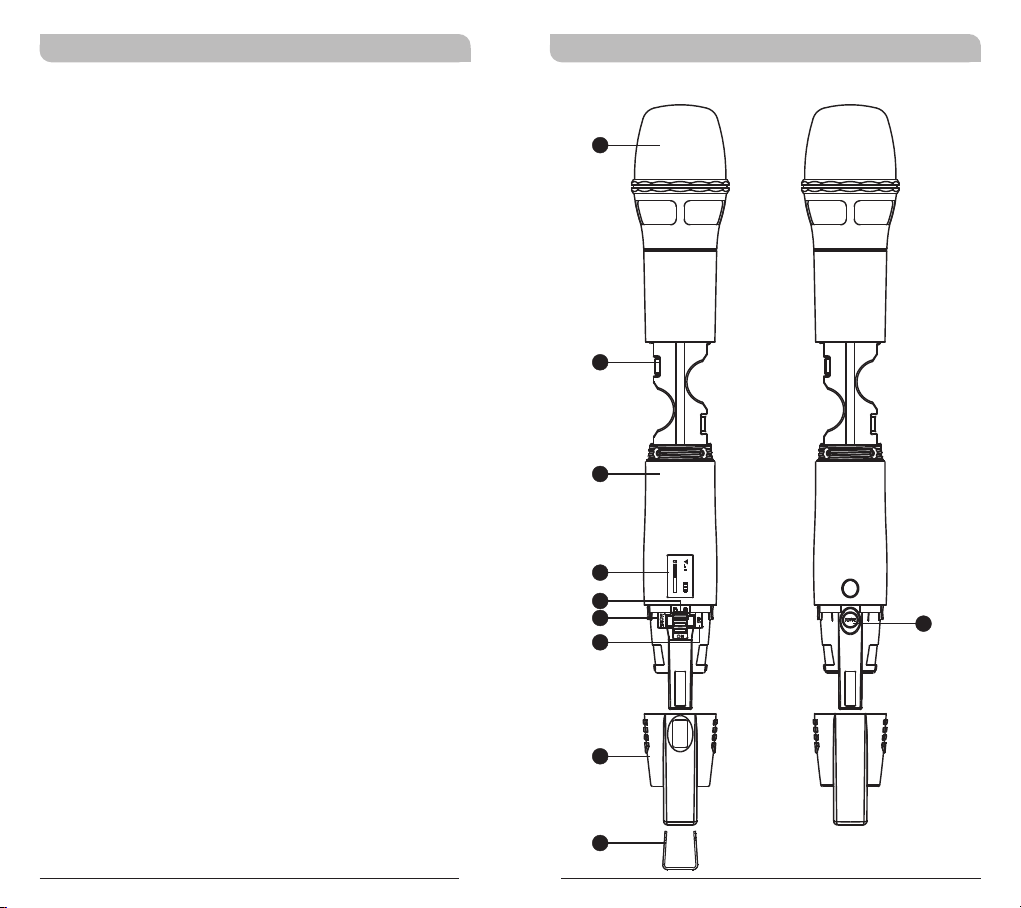
1
Capsule Module: Protects detachable
microphone capsule module and internal foam
prevents breathing, wind and POP noises.
2
Battery Compartment: Holds 2 'AA' batteries.
3
Housing: Protects transmitter PCB, battery
compartment and batteries.
4
LCD Panel: Displays transmitter parameters.
5
Power On/Off Switch: Slides the power switch
to the “ON” position for use or to the “OFF”
position when not in use.
6
MODE Button: Allows access to 8 available
functions displaying in LCD panel.
7
SET Button:
8
MUTE Button: To mute and un-mute the audio
Parameter selection button.
signal temporary.
9
Protection Cover: Protects power switch and
prevents user has direct access to power switch.
10
Channel ID Clip: For channel identification
(Optional)
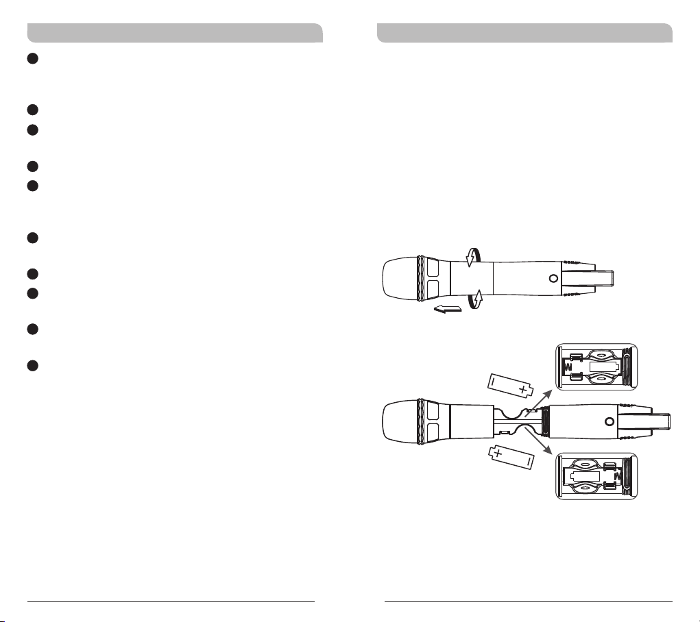
Operating Instructions for Insertion &
Removing Battery
!
Turn the microphone housing and pull it toward
capsule grille to expose battery compartment.
Insert two new AA alkaline batteries in the
!
battery compartment with correct polarity
orientation.
Turn power switch to ON position after battery
!
installation. If LCD does not lit, please check
battery polarity or change to fresh batteries.
Caution:
Always power off after each use. Remove the
internal battery if it will not be used for an
extended period of time.
2
3
Page 4
Handheld Transmitter Handheld Transmitter
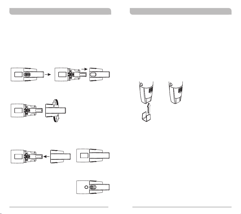
Patented Protection Cover
Protection cover's patented design protects
accidental access to power switch and its rugged
material and snug fit offer protection to both power
switch and PCB during accidental drop.
Steps:
! Remove protection cover.
!
Reverse protection cover.
! Install the protection cover after turning will
cover up power switch.
! When power is off, reverse-installation of
protection cover will turn on the switch
automatically. To turn off the system, remove
the cover to turn off.
! Protection cover must be attached during
operation for full protection.
! Channel identification clip can be attached to the
bottom of protection cover.
Mute function is open for easy acsess
4
5
Page 5
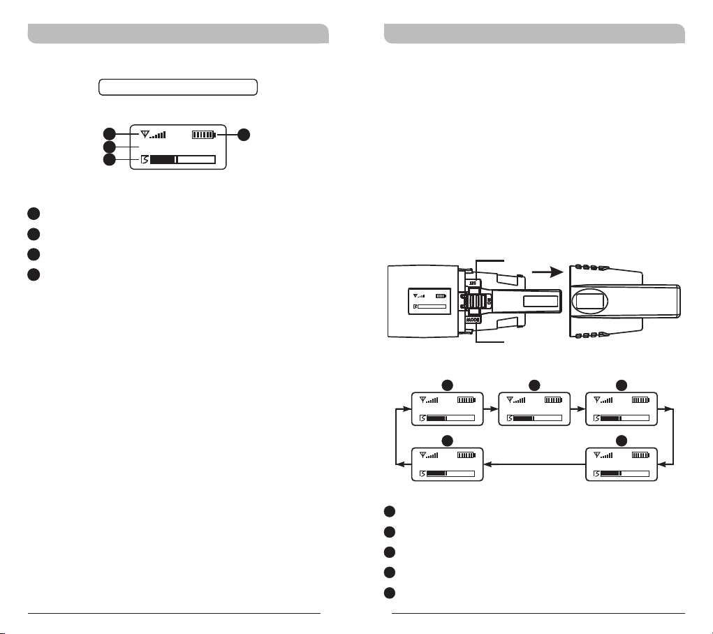
LCD Display Screen
Handheld Transmitter Handheld Transmitter
How to Setup Transmitter Parameters
Fully Lit LCD Display
A1
A2
A3
A1
Transmitted RF Signals
A2
Current Function Display
A3
AF (audio) MUTE
A4
Transmitter Battery Meter
CH 1 2
! Remove protection cover to expose MODE
button and SET button.
! MODE Button
A4
Press “MODE” button to access one of the six
functions below.
! SET Button
Press “SET” button and LCD wills start flashing.
During flashing, press SET button to change
parameters.
SET
868 .125
MHz
MODE
A
CH 01
E
RF Mid
B
868.500MHz
C
Gain 0dB
D
MANUAL
A
Channel
B
Frequency
C
Sensitivity Level
D
MUTE Mode
E
RF Output Power
6
7
Page 6
Handheld Transmitter Handheld Transmitter
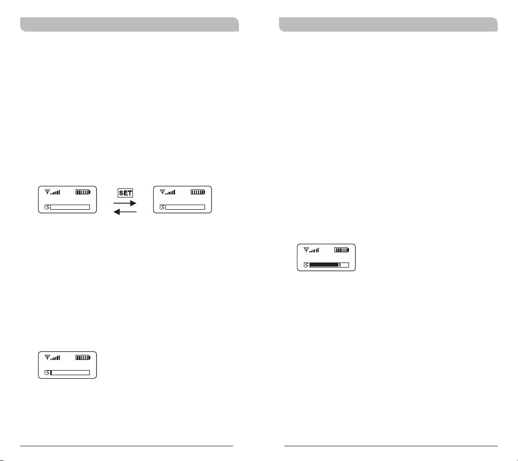
Channel Set-Up
! Press MODE button until CH mode appears.
! Press SET button once to activate function. CH
00 blinks once when activated.
! Press SET button increases the channel number
by one.
! Press MODE button to confirm and save the
change.
CH 01 CH 16
Frequency
! The displayed frequency corresponds to the
selected channel number. Frequency cannot be
changed.
Sensitivity Level Set-Up
! Gain Levels: Microphone Input (-12dB ~ 9dB).
! Press MODE button until Gain mode appears.
! Press SET button once to activate function. Gain
0 dB blinks once when activated.
! Press SET button for -12, -9, -6, -3, 0, 3, 6, or
9 dB.
! Press MODE button to confirm and save the
change.
Note:
! Ap prox ima tely 70% o f the leve l ind icat or i s
op tima l and reco mmen ded.
Gain- 9dB
86 8.1 2 5
MHz
8
9
Page 7
Handheld Transmitter Handheld Transmitter
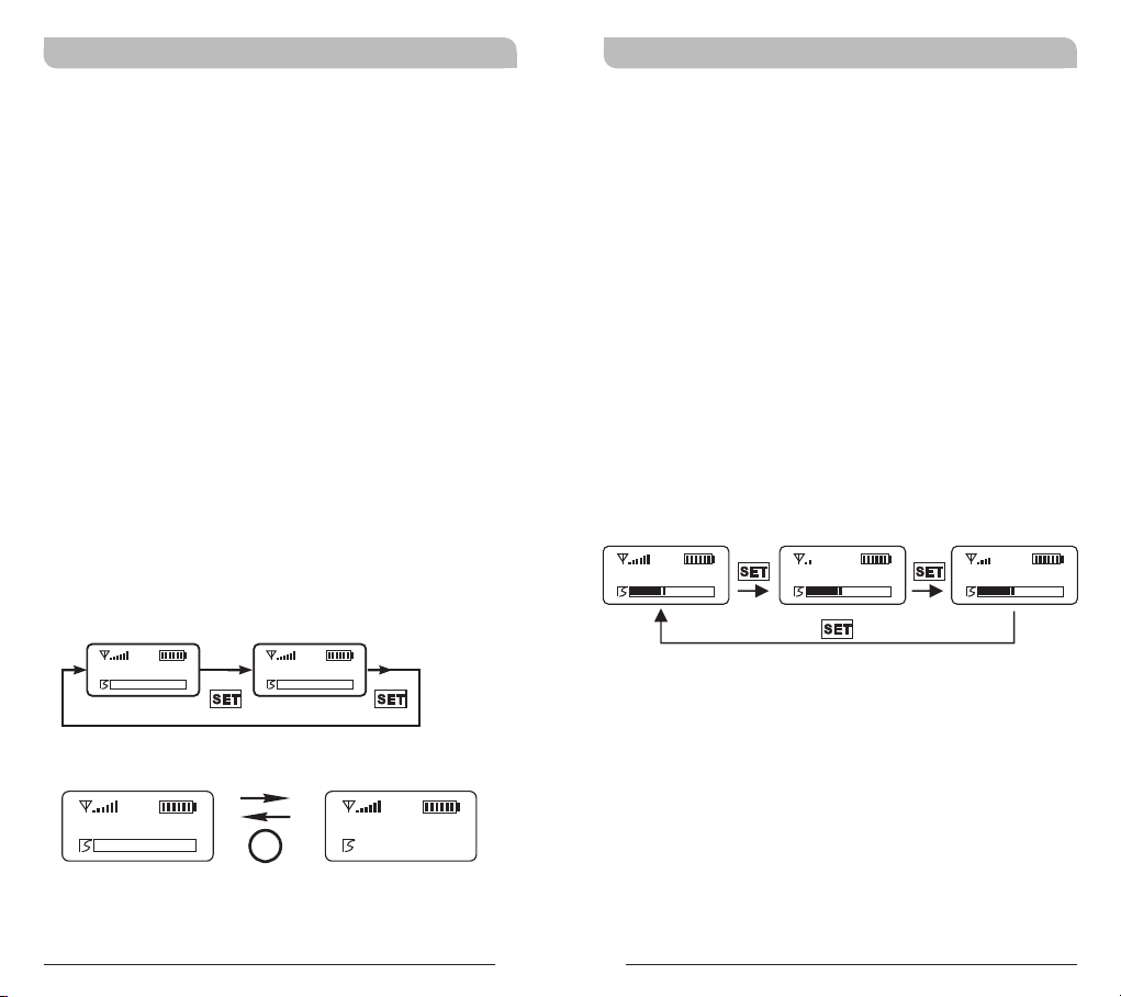
MUTE MODE: Mute model selection
! Press MODE button for selection of MUTE MODE.
Selection of MANUAL or DISABLE can be selected
once the MUTE MODE LCD starts blinking.
! Press SET button to select and set MANUAL or
DISABLE.
! LCD will stop blinking and change will not be
saved if setting is not done within 5 seconds.
! MANUAL: Mute function is controlled by the Mute
button at “MANUAL” mode.
! Press Mute button to enter mute status. At
mute status, AF indicators will become “AF
MUTE” and blink continuously. Press Mute
button again to release mute status.
! AF MUTE status will be released automatically
when turning off.
! DISABLE: MUTE button is not operable.
MA NUA L
DISABLE
RF Output Power Set-Up
! Press MODE button until RF mode appears.
! Press SET button once to activate function. RF Hi,
Mid or Low blinks once when activated.
! Press SET button for Hi, Mid or Low power.
! Press MODE button to confirm and save the
change.
Notes:
* Low or Mid setting is recommended for indoor,
smaller environment.
* Hi setting has 10mW RF power output.
RF Low RF MidRF Hi
MA N UAL
MUTE
MA N UAL
AF MUT E
10
11
Page 8
Handheld Transmitter Handheld Transmitter
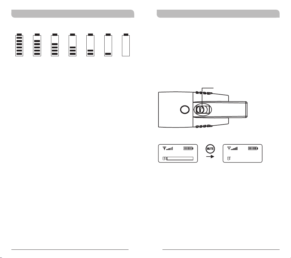
Battery Level Status
10 0% 80 % 60 % 40 % 20 % 10 %
! Change to new, fresh battery when zero or one
level indicator (10%) remains or when the
battery icon is flashing indicating a lower battery
level. Power will shut-off automatically if
continuous use without changing to protect from
being overly discharged.
Notes:
! The portable receiver and transmitter are
equipped with a programmable automatic shutoff timer which, upon expiration will turn off.
! The shut-off timer is pre-programmable with
MIPRO PC interface software and is currently
factory set for a duration of 6 hours (360
minutes).
! Thirty (30) seconds before the shut-off timer
elapses a TIME OUT message will appear on the
LCD screen and then it will be powered off
automatically to conserve the battery.
閃爍
Setting MUTE
! Press MUTE button to enter MUTE mode.
! Press MUTE button again to release mute status
; AF MUTE status will be released automatically
when turning off.
! MUTE button can be activated at “MANUAL”
mode.
MUTE
MA N UAL
MA N UAL
AF MUT E
12
13
Page 9

Handheld Transmitter Handheld Transmitter
General Tips for Improving System
Performance
1. Performer should avoid holding the microphone over
or near the antenna section as this will deteriorate
transmission efficiency. Severe deterioration if
performer directly covers up the antenna section with
both hands.
2. Many performers tend to hold the microphone by the
top grille. Unfortunately, this position seriously
degrades both the sound quality and directionality of
a microphone. Even the most expensive microphones
will have its original sound quality compromised by
this method. Grabbing a microphone by the grille will
isolate the capsule's acoustic resonance circuit and or
change the capsule resonator's frequency. This
results in an inferior performance in both frequency
response and the separation of directionality. In
addition, a palm's sound-focusing effect will tend to
strengthen resonances in certain frequencies and can
cause unwanted echo.
3. A proper technique is required for using directional
microphones because the distance between the
microphone and your mouth has a significant impact
on sensitivity and performance. There is an inverse
relationship between microphone sensitivity and the
distance from the mouth to the microphone.
Consequently, performers with a ''weaker'' sound
level cannot expect to hold the microphone too far
away from their mouth and compensate by turning
up the amplifier volume to increase the sound level
as this can easily cause echo or feedback. In
contrast, performers with a ''louder'' sound level
should not hold the microphone too close as this can
easily result in distortion by causing the amplifier
system to be overloaded.
14
4. Furthermore, a large-diaphragm directional
microphone has a very distinct proximity effect.
When the microphone is close to the mouth, the
bass response is strengthened as the distance gets
closer. Therefore, if a performer's sound is
insufficient in bass, they can hold the microphone
closer and use the proximity effect to help
compensate for the lower bass level. Conversely, if a
performer's voice is too heavy in the bass register,
increasing the distance between the microphone and
their mouth will decrease the proximity effect and
reduce the bass response, thus making their voice
become clearer and brighter.
5. It is recommended to keep the grille and sponge
windscreen clean to avoid any substance blocking the
proximity effect of the microphone.
Notes
1. Refer to actual product in the event of product
description discrepancy.
2. Frequency range and maximum deviation comply
with the regulations of different countries.
15
Page 10

FCC
Federal Communication Commission Interference
Statement
This equipment has been tested and found to
comply with the limits for a Class B digital device,
pursuant to Part 15 of the FCC Rules. These limits
are designed to provide reasonable protection
against harmful interference in a residential
installation.
This equipment generates, uses and can radiate
radio frequency energy and, if not installed and
used in accordance with the instructions, may cause
harmful interference to radio communications.
However, there is no guarantee that interference
will not occur in a particular installation. If this
equipment does cause harmful interference to radio
or television reception, which can be determined by
turning the equipment off and on, the user is
encouraged to try to correct the interference by one
of the following measures:
! Reorient or relocate the receiving antenna.
! Increase the separation between the equipment
and receiver.
! Connect the equipment into an outlet on a
circuit different from that to which the receiver
is connected.
! Consult the dealer or an experienced radio/TV
technician for help.
FCC Caution: To assure continued compliance, any
changes or modifications not expressly approved by
the party responsible for compliance could void the
user's authority to operate this equipment.
(Example - use only shielded interface cables when
connecting to computer or peripheral devices).
FCC Radiation Exposure Statement
This equipment complies with FCC RF radiation
exposure limits set forth for an uncontrolled
environment.
For the Handheld Wireless Microphone:
When transmitting, hold the radio in a vertical
position with its microphone 0.5 cm away from your
mouth and keep the antenna at least 0.5 cm away
from your head and body.
This transmitter must not be co-located or
operating in conjunction with any other antenna or
transmitter.
Page 11
This device complies with Part 15 of the FCC Rules.
Operation is subject to the following two conditions:
(1) This device may not cause harmful interference,
and (2) This device must accept any interference
received, including interference that may cause
undesired operation.
THIS DEVICE COMPLIES WITH 15.247 OF THE FCC RULES.
OPERATION IS SUBJECT TO THE FOLLOWING TWO
CONDITIONS:
(1) This device may not cause interference.
(2) This device must accept any interference, including
interference that may cause undesired operation of the
device.
This equipment complies with FCC RF radiation exposure
limits set forth for an uncontrolled environment.
WARNING
1. FOR OUTDOOR USE:
To reduce the risk of fire or electric shock, do not expose
this apparatus to rain or moisture.
2. UNDER WET LOCATION:
Apparatus should not be exposed to dripping or splashing
and no objects filled with liquids, such as vases should be
placed on the apparatus.
3. SERVICE INSTRUCTIONS:
CAUTION - These servicing instructions are for use by
qualified service personnel only. To reduce the risk of
electric shock, do not perform any servicing other than that
contained in the operating instructions unless you are
qualified to do so.
IC
This device complies with Industry Canada RSS-210
ISSUE 8 standards. Operation is subject to the following
two conditions:
(1) this device may not cause interference, and
(2) this device must accept any interference, including
interference that may cause undesired operation of the
device.
Le présent appareil est conforme aux CNR d'Industrie
Canada applicables aux appareils radio exempts de licence.
L'exploitation est autorisée aux deux conditions suivantes:
(1) l'appareil ne doit pas produire de brouillage, et
(2) l'utilisateur de l'appareil doit accepter tout brouillage
radioélectrique subi, même si le brouillage est susceptible
d'en compromettre le fonctionnement.
Disposal
2005 -08-1 3
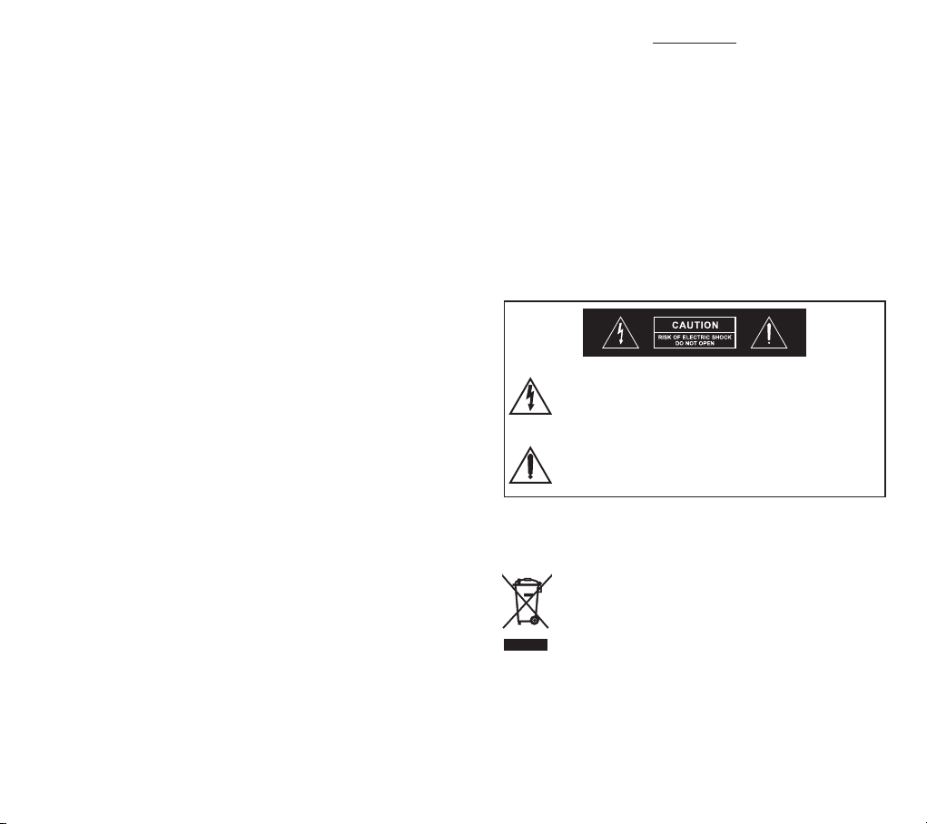
This symbol indicates that dangerous voltage
constituting a risk of electric shock is present within
this unit.
This symbol indicates that there are important
operating and maintenance instructions in the
literature accompanying this unit.
Dispose of any unusable devices or batteries
responsibly and in accordance with any applicable
regulations.
Disposing of used batteries with domestic waste is
to be avoided!
Batteries / NiCad cells often contain heavy metals
such as cadmium(Cd), mercury(Hg) and lead(Pb)
that makes them unsuitable for disposal with
domestic waste. You may return spent batteries/
accumulators free of charge to recycling centres or
anywhere else batteries/accumulators are sold.
By doing so, you contribute to the conservation of
our environment!
 Loading...