

Page 1
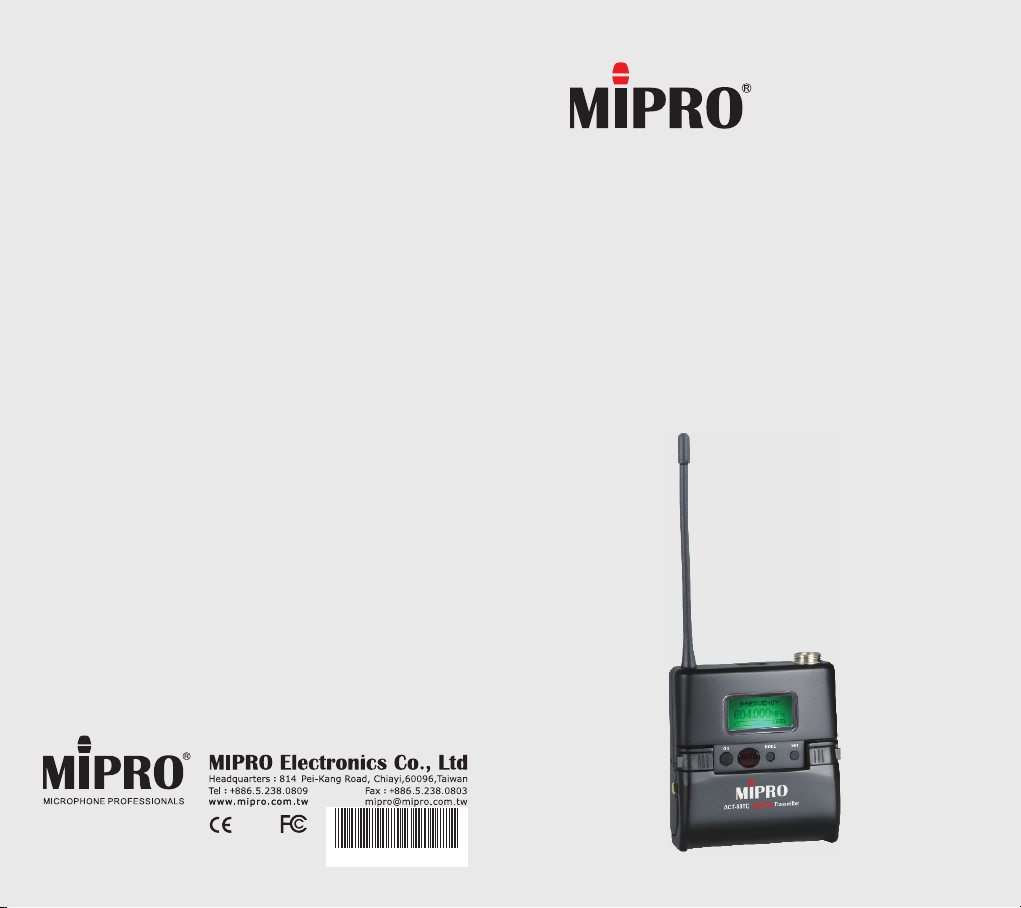
ACT-80TC
DIGITAL TRANSMITTER
User Guide
All rights reserved.
Do not copy or forward without prior approvals MIPRO.
Specifications and design subject to change without notice.
MN 015/01
2 CE 5 1 5 A
Page 2
Rechargeable Digital Wideband Bodypack Transmitter Rechargeable Digital Wideband Bodypack Transmitter
Contents Bodypack Controls and Indicators
1 Bodypack Controls and Indicators
4 O
5 LCD
perating Instructions
Display Screen
1
2
6
How to Setup Transmitter Parameters
19 Battery Status
21
25 AF
26 B
MUTE Control Set-Up
Input Connections
attery Removal and Installation
3
4
5
6
7
8
9
10
11
12
FREQ UENCY
485.000MHz
ON MODE
13
SET
14
15
0
1
Page 3

Rechargeable Digital Wideband Bodypack Transmitter Rechargeable Digital Wideband Bodypack Transmitter
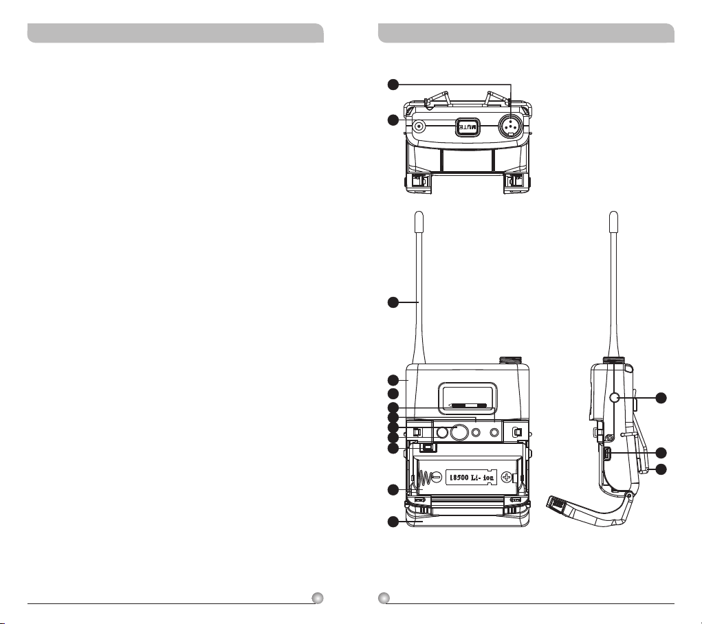
1
Audio Input Connector: TA4F mini 4-pin
connector accepts any MIPRO lavalier,
instrument and headset microphones and
cables. (See 5 ways of connection on AF Input
Connections)
2
MUTE Button: To mute and un-mute the audio
signal temporary.
3
Antenna: Flexible 1/ 4 wave transmitting
antenna.
4
Transmitter Housing: Holds PCB board and
wires.
5
LCD Panel: Display transmitter parameters.
6
SET Button: Parameter selection button.
7
MODE Button: Allows access to available
functions displaying in LCD panel.
8
ACT IR Port: Align and syncs the transmitter
and receiver frequency automatically.
9
Power Button: Press and hold 2 seconds to
power ON or OFF.
10
Battery Circuitry Protection Reset Button
11
Battery Compartment: Accommodates one
18500 rechargeable battery.
12
Battery Cover: Hinged cover opens to provide
access to one 18500 rechargeable battery.
13
External Mute Connector: When an external
mute switch cable, MJ-70 (optional) is connected
, user can manually mute and un-mute the
audio temporary.
14
Battery Charging Contact: Align contacts
during charging.
15
Belt Clip: Detachable and reversible design
allows the transmitter to be worn on a belt,
waistband, or guitar strap ( .Figure 1)
(Positive Wear)
(Opposite Wear)
32
(Figure 1)
Page 4
Rechargeable Digital Wideband Bodypack Transmitter Rechargeable Digital Wideband Bodypack Transmitter
Operating Instructions
!
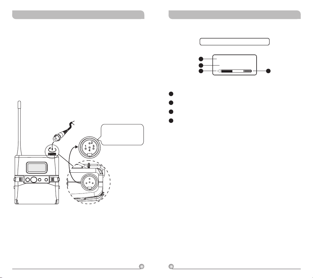
Insert the lavalier, headset microphone or
instrument cable into the audio input connector
before power ON the transmitter.
Tighten the connector screw clockwise direction
!
as shown in (Figure 2) for a secured fit.
! Please make sure sensitivity level is set at
proper level.
Capsule Connector
Headset
ON MODE
Lavalier
SET
The ridge on the
connector must align and
match the indentation on
the socket when inserting
for a proper fit.
(Figure 2)
LCD Display Screen
Fully Lit LCD Display
14
15
16
14
LCD Screen
15
Parameters Screen
16
AF (audio) MUTE
17
Transmitter Battery Meter
GRP CH
0 1 0 2
17
4
5
Page 5

Rechargeable Digital Wideband Bodypack Transmitter Rechargeable Digital Wideband Bodypack Transmitter
How to Setup Transmitter Parameters
! MODE Button:
Press “MODE” button to access one of the NINE
functions below.
! SET Button:
Press “SET” button and LCD wills start flashing.
During flashing, press SET button to change
parameters.
FREQU ENCY
485.000MHz
ON MODE
SET
MODE
SET
A
GRP CH
0 1 0 2
F
ENC RYPTIO N
N O
G
RF P OWER
RF-L O W
A
Group and Channel
B
Frequency
C
Sensitivity Level
D
AF Low Cut
E
AF Limit
F
Encryption
G
RF Output Power
H
AF Phase
I
Parameters Lock & Unlock Status
J
MUTE MODE
B
FRE QUENC Y
485.000MHz
E
AF L IMIT
Y E S
H
AF P HASE
INVE R T
C
AF G AIN
0 dB
D
AF L OW-CU T
LOW CUT
I
SET LOCK
UNLO C K
J
MUT E MODE
MANU A L
6
7
Page 6
Rechargeable Digital Wideband Bodypack Transmitter Rechargeable Digital Wideband Bodypack Transmitter
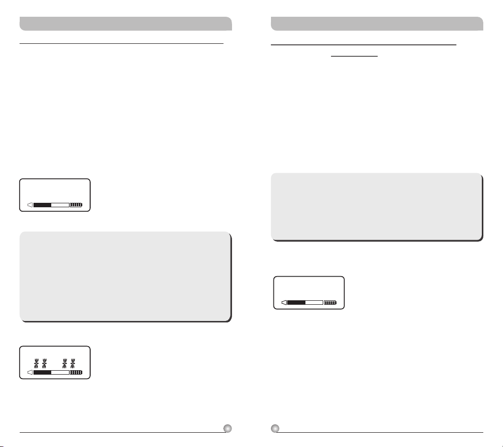
GRP CH: Displays Group and Channel Information
a. Press MODE and stop on the GRP CH function;
the display showing the current group and
channel will be flashing. After 5 seconds, the
display will stop flashing and the current group
and channel selection will be set.
b. The group and channel information is now
shown on the display. Changing the current
group and channel must be done on the
receiver.
GRP CHGRP CH
0 1 0 2
**Note:
When programming a special frequency via
monitoring software, the LCD screen cannot
display the number. This is because this special
channel is not in the preset group and channel.
RF, the LCD panel will look like the illustration
below.
FREQUENCY: Displays Transmitter Frequency
Information
a. Press MODE and stop on the FREQUENCY
function; the display showing the current
frequency will be flashing. After 5 seconds, the
display will stop flashing.
b. The frequency information is now shown on the
display. Changing the current frequency must be
done on the receiver.
**Note:
To modify the transmitter's group, channel and
frequency, all three must be set at the receiver
and the new setting transmitted to the
transmitter via the ACT function.
FR EQ UE NC Y
485.000MHz
GRP CH
8
9
Page 7
Rechargeable Digital Wideband Bodypack Transmitter Rechargeable Digital Wideband Bodypack Transmitter
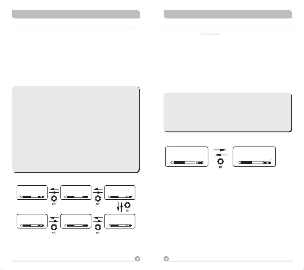
AF GAIN: Setup and Change of Input Sensitivity
a. Press MODE and stop on the AF GAIN function;
the display showing the current status will be
flashing and is ready to be modified.
b. Every push of the SET button increases the dB
value by 6dB to a maximum of 18dB.
**Note:
1. The higher the gains are set, the lower the
dynamic range for signal input and the
greater the danger of unwanted noises and
feedback getting into the system.
2. When using electronic guitar, gain should set
at 0dB.
3. Please make sure input signal strength does
not exceed 2 Vrms (gain=6dB) as it is the
maximum input strength allowed for
transmitter without causing distortion.
AF G AIN
-12 dB
AF G AIN
-6 dB
AF G AIN
0 dB
AF LOW-CUT: Setup and Change of Low Frequency
Cut Off
a. Press MODE and stop on the AF LOW-CUT
function; the display showing the current status
will be flashing and is ready to be modified.
b. Press the SET button while the display is
flashing to change to LOW CUT or FLAT as
desired.
**Note:
When the AF LOW-CUT function is LOW CUT,
the frequency response below 100Hz will
decrease about 3dB with a slope of 6dB/Octave.
AF LO W-C UT
LOW CUT
AF LO W-C UT
FLAT
AF G AIN
18 dB
AF G AIN
12 dB
AF G AIN
6 dB
10
11
Page 8
Rechargeable Digital Wideband Bodypack Transmitter Rechargeable Digital Wideband Bodypack Transmitter
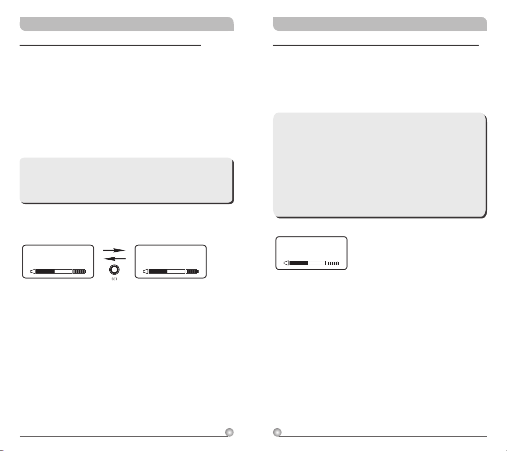
AF LIMIT: Setup and Change of Input Limit
a. Press MODE and stop on the AF LIMIT
function; the display showing the current status
will be flashing and is ready to be modified.
b. Press SET while the display is flashing to change
the setting to ON or OFF.
**Note:
When the LIMIT is ON, the maximum output of
the receiver is limited to 1V.
AF LI MI T AF LI MI T
Y E S N O
ENCRYPTION: Displays Information of Encryption
a. Press MODE and stop on the ENCRYPTION
function; the display showing the current status
will be flashing.
**Note:
1. The ENCRYPTION function displays status
information only. Changing of the current
status must be done from the receiver via
the ACT function.
2. The ENCRYPTION function must be set at
receiver first then using ACT to program the
transmitter.
EN CRY PT IO N
N O
12
13
Page 9
Rechargeable Digital Wideband Bodypack Transmitter Rechargeable Digital Wideband Bodypack Transmitter
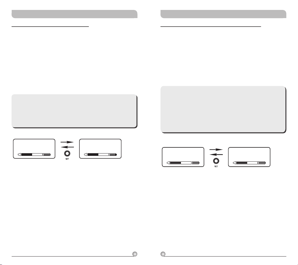
RF POWER: RF Power Selection
a. Press MODE button for selection of RF POWER.
Selection of RF-HI or RF-LOW can be selected
once the RF POWER LCD starts blinking.
b. Press SET button to select and set RF-HI or
RF-LOW.
**Note:
RF-HI has 50mW transmitting power. RF-LOW
has 10mW transmitting power. Set appropriate
power to meet region/country regulations.
RF PO WE R
RF - HI
RF PO WE R
RF - LO W
AF PHASE: Phase Selection of AF inputs
a. Press MODE button for selection of AF PHASE.
Selection of NORMAL or INVERT can be
selected once the AF PHASE LCD starts
blinking.
b. Press SET button to select and set NORMAL or
INVERT.
**Note:
AF PHASE function provides users a phase
selection for different condenser microphones.
The normal setting is NORMAL, and INVERT
might be selected if two-wire condenser
microphone is used.
AF PH AS E
NO R MA L
AF PH AS E
IN V ER T
14
15
Page 10
Rechargeable Digital Wideband Bodypack Transmitter Rechargeable Digital Wideband Bodypack Transmitter
SET LOCK: Setup and Change of Parameter Lock
a. Press MODE button once for SET LOCK display.
Once SET LOCK display starts blinking it is
ready for selection.
b. Press SET button for UNLOCK or LOCK
selection.
**NOTE:
1. When locked (LOCK), receiver settings
cannot be changed including the powering on
& powering off. To power off it needs to be
in unlock mode (UNLOCK).
2. A sudden lose of power will deactivate the
LOCK Function.
3. MUTE function can be operated normally
during LOCK mode.
SE T L OC K
UN L OC K
SE T L OC K
LO C K
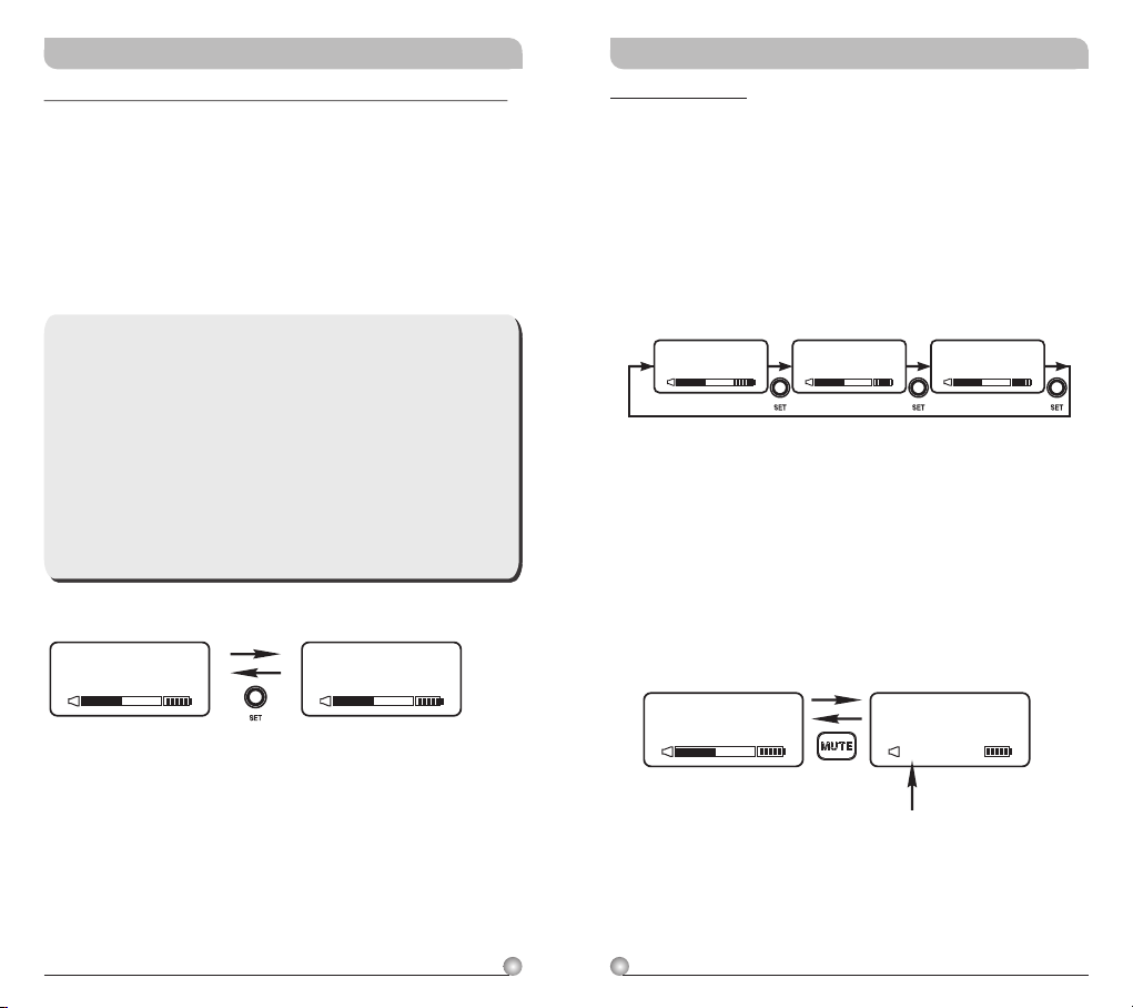
MUTE MODE
a. Press MODE button until MUTE MODE icon
appears and flashes.
b. Press SET button to select MANUAL, DISABLE
or PUSH-OFF setting.
c. Setting needs to be completed within 5 seconds
to be saved. Set again if flash stops before
completion.
MUT E MODEMUT E MODEMUT E MODE
DISABLEMANUAL PUSH-OFF
d. MANUAL: e.Standard setting where mute function
can be controlled by mute button.
Audio is muted when MUTE button is pressed
!
and AF MUTE indicator starts flashing. Press
MUTE button again to cancel.
AF MUTE cancels automatically when power
!
off.
MU TE MO DE
MA N UA L
MU TE MOD E
MU T E
AF MUT E
AF MUTE
blinks continuously
DISABLE:
MUTE button is disabled and mute
function is cancelled.
16
17
Page 11
Rechargeable Digital Wideband Bodypack Transmitter Rechargeable Digital Wideband Bodypack Transmitter
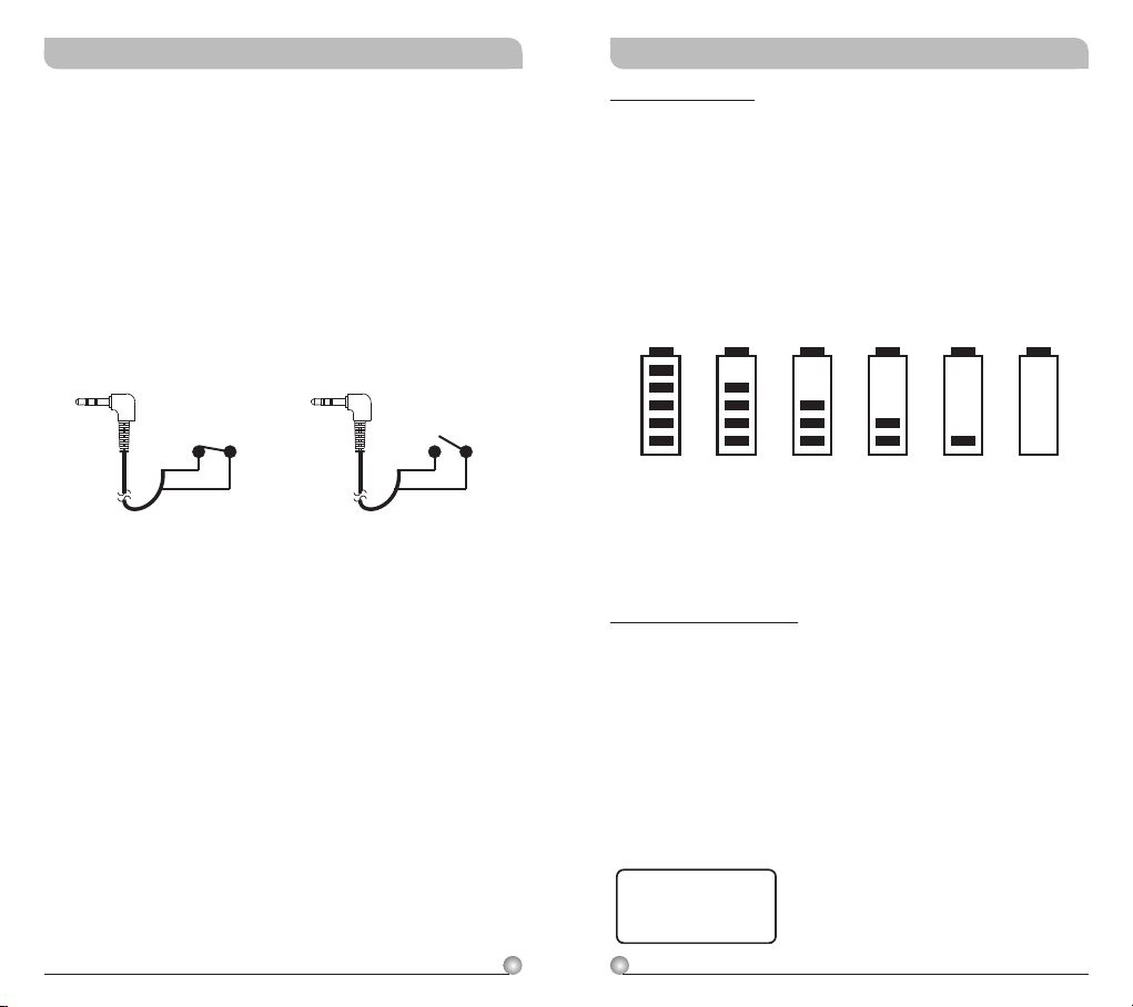
f. PUSH-OFF:
!!Press and hold MUTE button to mute
continuously. Press and release MUTE button
to un-mute.
Under this mode, an optional MJ-70, Remote
Mute Switch (not included), can be used to
MUTE and un-mute externally.
Battery Status
Indicates the power remaining in the transmitter
battery. When the battery has less than 10% power
remaining it must be replaced or recharged. If an
under voltage condition continues, the LCD will
show “OFF...” and the system will shut down to
prevent being overly discharged.
MUTE ON audio is muted. MUTE OFF audio is on.
MUTE ON MUTE OFF
10 0% 80 % 60% 40% 20% 10 %
“OFF...” : Power Off
1. Press and hold power button for 2 seconds to
power on & off.
2. When the power switch is turned off, the LCD
will show “OFF…” (for Power Off) first and then
the system will shut down and no further
messages will be displayed.
OF F. . .
18
19
Page 12
Rechargeable Digital Wideband Bodypack Transmitter Rechargeable Digital Wideband Bodypack Transmitter
ERR: Error Code
If the LCD displays “ERR” after turning on the
power, it indicates the operation is not correct. The
error codes are as follows:
ROM-ER → Transmitter does not have the initial
data so the microphone is completely
dead and cannot be programmed.
ERROR1 → Failure on RF circuitry, frequency
cannot be programmed.
NO----OR3 → Frequency to be programmed into
the transmitter exceeds the highest
frequency of the designated
frequency band of the transmitter.
NO----OR4 → Frequency to be programmed into
the transmitter exceeds the lowest
frequency of the designated
frequency band of the transmitter.
**Note:
NO----OR3 and NO----OR4 will not change the
transmitter's original frequency and the
transmitter will still operate normally with the
error message on display. To remove the error
message from the display panel, please switch
off the transmitter and switch it on again.
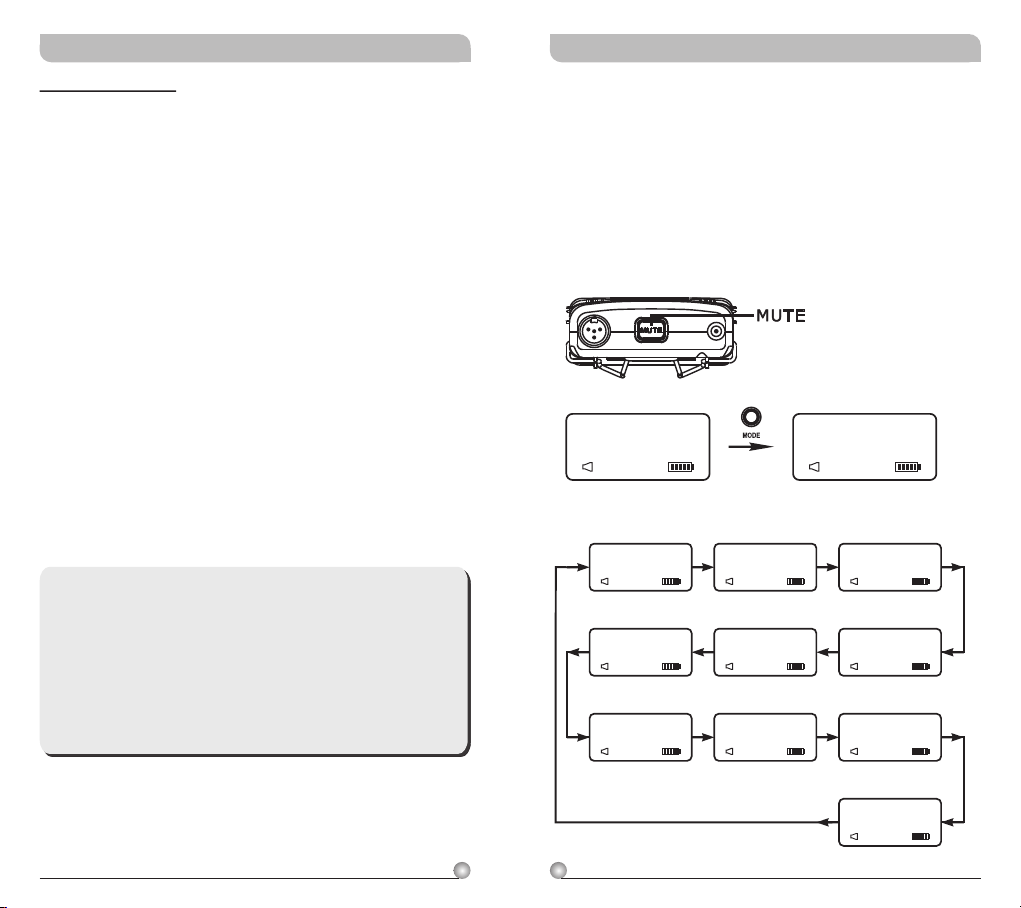
MUTE Control Set-Up
MUTE control enables audio to be muted or
un-muted temporarily.
!
Press MUTE button to mute audio temporarily.
Parameter values can be changed and ACT sync
activate during this MUTE mode.
Press MUTE button to un-mute.
!
GRP CH
M U T E
AF MUT E
(GROUP/CHANNEL)
GRP CH
0 1 0 2
AF M UTE
(ENCRYPTION)
ENC RYPTIO N
N O
AF M UTE
(RF POWER)
RF P OWER
RF-L O W
AF M UTE
(FREQUENCY)
FRE QUENC Y
485.000MHz
AF M UTE
(AF LIMIT)
AF L IMIT
Y E S
AF M UTE
(AF PHASE)
AF P HASE
INVE R T
AF M UTE
FR EQ UE NC Y
485.000MHz
AF MUT E
(AF GAIN)
AF G AIN
0 dB
AF M UTE
(AF LOW-CUT)
AF L OW-CU T
LOW CUT
AF M UTE
(SET LOCK)
SET LOCK
UNLO C K
AF M UTE
(MUTE MODE)
MUT E MODE
MANU A L
AF M UTE
20
21
Page 13
Rechargeable Digital Wideband Bodypack Transmitter Rechargeable Digital Wideband Bodypack Transmitter
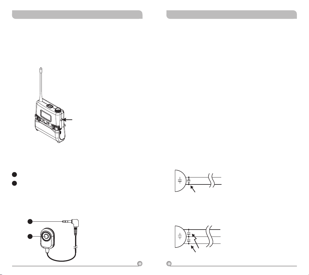
External Mute Connector
! External mute connector is a 3.5mm jack. When
an external mute switch cable, MJ-70 (optional)
is connected, user can manually mute and un-
mute the audio temporary.
External mute connector
MJ-70 External Mute Switch (optional)
B1
3.5mm jack.
B2
External mute switch on/off button.
NOTE: Plug in the device before power on the
bodypack transmitter.
High Frequency Bypass
a. When other microphones are in use, some
changes may be needed to another microphone
before adding it to the system in order to avoid
high frequency interference, as illustrated in
diagram (1).
b. When a high frequency radio wave causes
interference, it normally affects the system by
generating a persistent noise or by deteriorating
the frequency response. In an effort to
ameliorate these problems, a 330PF bypass
condenser can be added on the cartridge as
shown in diagrams (1) and (2). If this method is
not possible, another option is to add a bypass
condenser on the 4-pin XLR connector as shown
in diagrams (3) and (4).
**The Best Method
(1) Connect to two-wire condenser capsule
Add 330pF bypass capacitor
B1
B2
(2) Connect to three-wire condenser capsule
Add 330pF bypass capacitor
22
23
Page 14
Rechargeable Digital Wideband Bodypack Transmitter Rechargeable Digital Wideband Bodypack Transmitter
**Alternate Method
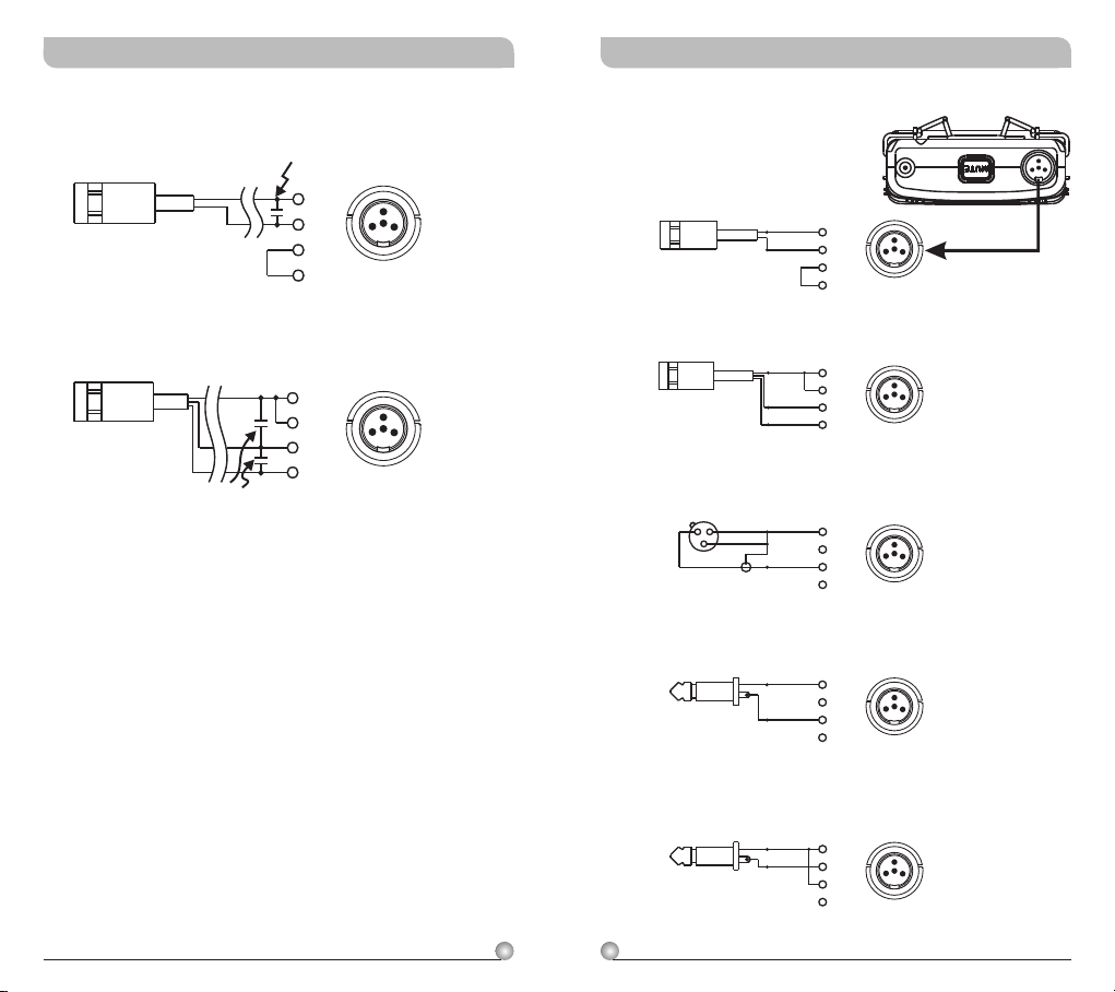
AF Input Connections
(3) Connect to two-wire condenser capsule
Add 330pF bypass capacitor
PIN
1
2
2
3
1
4
3
4
(1) 2-Wire Electret condenser
microphone Capsule
PIN
SHIELD
1
AUDIO
2
3
4
2
3
1
4
(4) Connect to three-wire condenser capsule
PIN
1
2
3
2
3
1
4
4
Add 330pF bypass capacitor
(2) 3-Wire Electret condenser microphone Capsule
PIN
SHIELD
1
2
3
AUDIO
BIAS
2
3
4
1
4
(3) Dynamic Microphone
2
1
3
SHIELD
AUDIO
PIN
1
2
3
2
3
4
1
4
(4) Electric Guitar
PIN
SHIELD
1
2
3
AUDIO
2
3
4
1
4
(5) Line-in (Impedance 8KΩ ATT. 10dB)
PIN
SHIELD
1
AUDIO
24
25
2
3
2
3
4
1
4
Page 15
Rechargeable Digital Wideband Bodypack Transmitter Rechargeable Digital Wideband Bodypack Transmitter
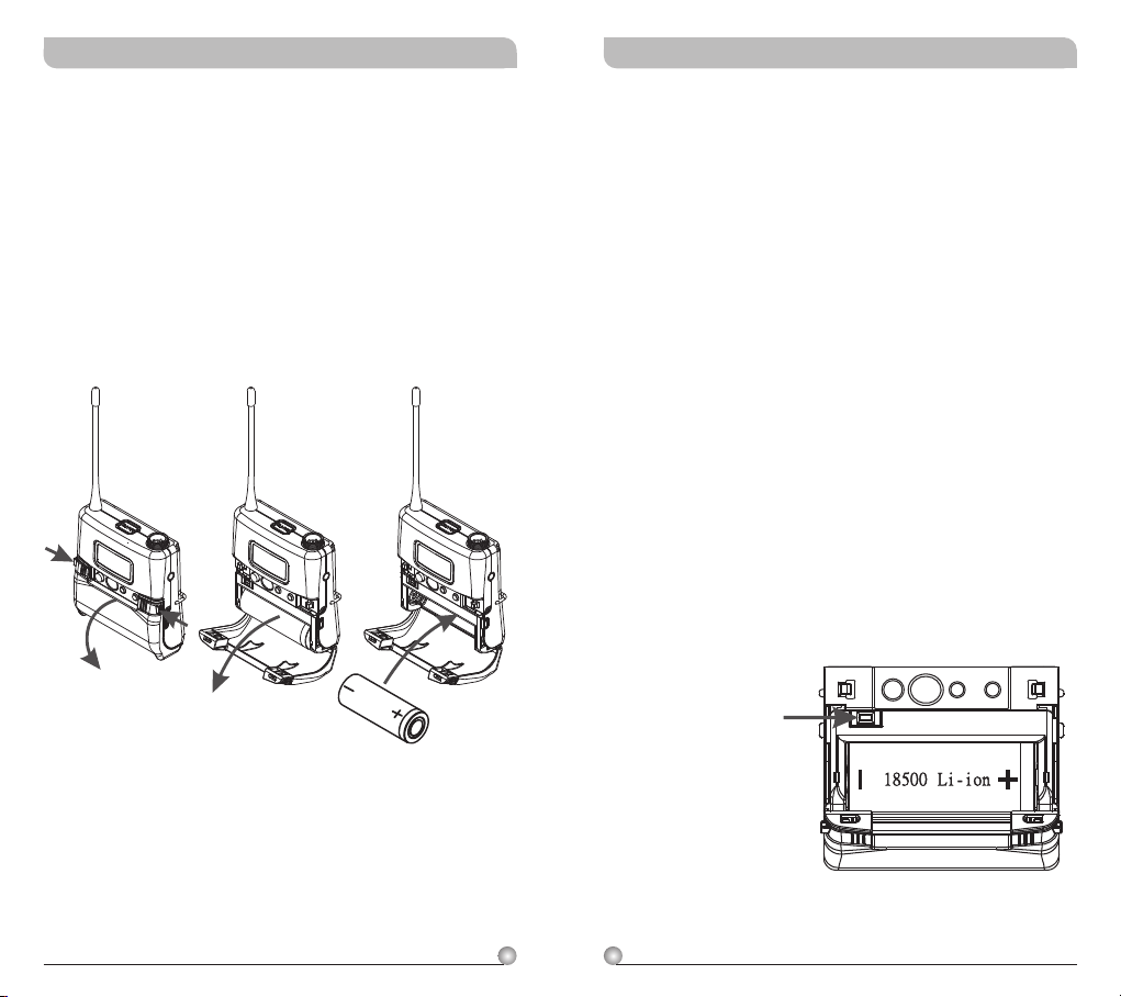
Battery Removal and Installation
! Pushing down both snap locks on the sides to
open battery compartment cover. Take out the
one
batteries. (Figure 3)
! Insert one charged 18500 rechargeable battery
into the battery compartment according to the
correct polarity (- and +) as shown in (Figure 4)
. Then close the battery compartment cover
tightly.
(Figure 4)(Figure 3)
Caution
Note: Transmitter cannot be powered on with
charged battery.
Method 1:
a. Ensure battery is inserted correctly with + top
side.
b. If battery is inserted correctly it could be due
to self battery protection mechanism. Insert the
transmitter into the charger to re-charge for
10-20 seconds to wake-up the battery. It
should work.
c. If charger cannot be used, reverse the battery
insertion for 10-20 seconds, wake up the
battery with correct polarity. It should work.
Method 2:
a. Power off the transmitter before open the
hinged cover. Press battery protection circuitry
reset button once to wake-up battery. Power on
the transmitter.
ON MODE
Battery Protection
Circuitry Reset Button
SET
Caution
Remove the batteries if unused for a long period of
time to prevent battery leakage, corrosion and
causes possible damage to electronics.
26
27
Page 16
Rechargeable Digital Wideband Bodypack Transmitter Rechargeable Digital Wideband Bodypack Transmitter
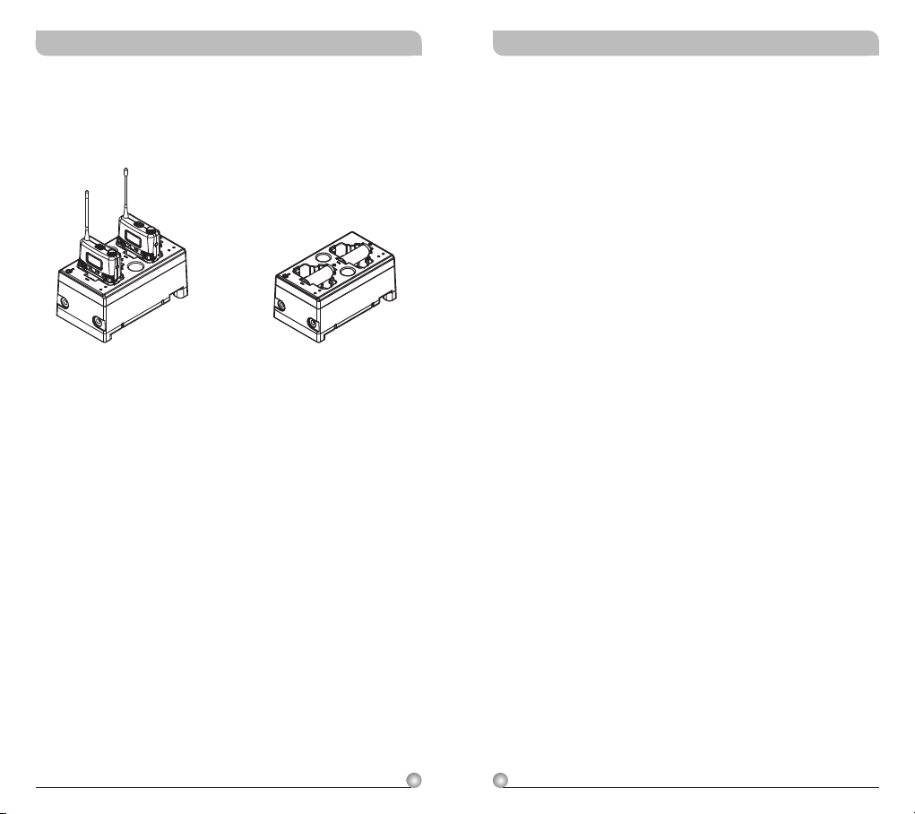
MP-80 Battery Charger (Optional)
MP-80 Charger charges both transmitters and
18500 rechargeable batteries.
Notes
1. Refer to actual product in the event of product
description discrepancy.
2. Frequency range and maximum deviation comply
with the regulations of different countries.
18500 Charging Transmitters Charging
28
29
Page 17
Rechargeable Digital Wideband Bodypack Transmitter Rechargeable Digital Wideband Bodypack Transmitter
FCC
THIS DEVICE COMPLIES WITH PART 74 OF THE FCC
RULES.
OPERATION IS SUBJECT TO THE FOLLOWING TWO
CONDITIONS:
(1) This device may not cause interference.
(2) This device must accept any interference, including
interference that may cause undesired operation of the
device.
This equipment complies with FCC RF radiation exposure
limits set forth for an uncontrolled environment.
IC
This device complies with Industry Canada RSS-210
ISSUE 8 standards. Operation is subject to the following
two conditions:
(1) this device may not cause interference, and
(2) this device must accept any interference, including
interference that may cause undesired operation of the
device.
Le présent appareil est conforme aux CNR d'Industrie
Canada applicables aux appareils radio exempts de licence.
L'exploitation est autorisée aux deux conditions suivantes:
(1) l'appareil ne doit pas produire de brouillage, et
(2) l'utilisateur de l'appareil doit accepter tout brouillage
radioélectrique subi, même si le brouillage est susceptible
d'en compromettre le fonctionnement.
WARNING
1. FOR OUTDOOR USE:
To reduce the risk of fire or electric shock, do not
expose this apparatus to rain or moisture.
2. UNDER WET LOCATION:
Apparatus should not be exposed to dripping or
splashing and no objects filled with liquids, such as
vases should be placed on the apparatus.
3. SERVICE INSTRUCTIONS:
CAUTION - These servicing instructions are for use by
qualified service personnel only. To reduce the risk of
electric shock, do not perform any servicing other than
that contained in the operating instructions unless you
are qualified to do so.
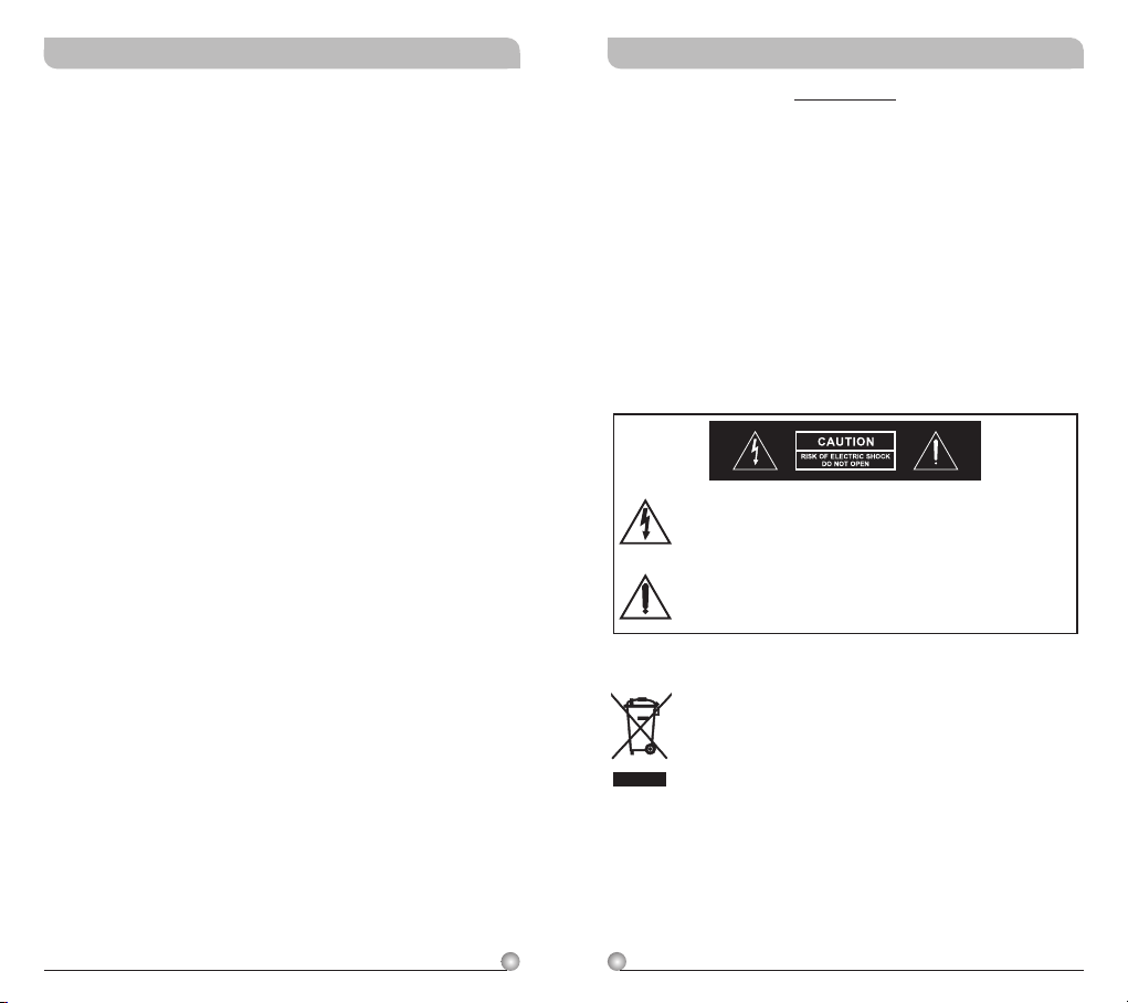
This symbol indicates that dangerous voltage
constituting a risk of electric shock is present
within this unit.
This symbol indicates that there are important
operating and maintenance instructions in the
literature accompanying this unit.
Disposal
2005 -08-1 3
30
31
Dispose of any unusable devices or batteries
responsibly and in accordance with any
applicable regulations.
Disposing of used batteries with domestic waste
is to be avoided!
Batteries / NiCad cells often contain heavy
metals such as cadmium(Cd), mercury(Hg) and
lead(Pb) that makes them unsuitable for
disposal with domestic waste. You may return
spent batteries/accumulators free of charge to
recycling centres or anywhere else batteries/
accumulators are sold.
By doing so, you contribute to the conservation
of our environment!
 Loading...