

Page 1
Disposal
2 CE24 3
Dispose the unusable device according to valid regulations.
Disposal of spent batteries/accumulators
You are required by law to return all spent batteries. Disposing of
used batteries with domestic waste is prohibited!
Batteries / NiCad cells containing toxins are marked
by accompanying symbols that refer to the
prohibition of disposal with domestic waste. The
designations for the decisive heavy metals are:
Cd=cadmium, Hg=mercury, Pb=lead. You may return
2005 -08-132005 -08-13
By doing so, you fulfil the legal requirements and contribute to the
conservation of our environment!
spent batteries/accumulators free of charge to the
recycling centres, our outlets or anywhere else
where batteries/accumulators are sold.
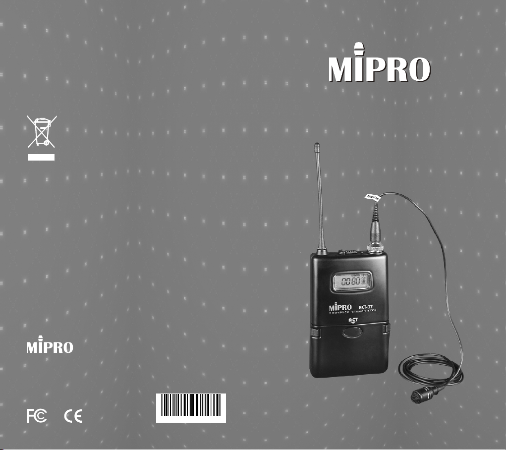
ACT-7T Wireless Microphone
User Guide
El ectro nics Co ., Ltd.
Headquarters: 814 Pei-Kang Road, Chiayi, 60096, Taiwan.
http://www.mipro.com.tw
E-mail: [email protected]
Design & specifications are subject to change without prior notice
AS100510
Page 2
Bodypack Transmitter
Bodypack Transmitter
Finely crafted and ergonomically designed
ACT-7T adapts magnesium alloy housing, LCD
panel, and high-efficient transmitting circuit
design with low spurious showcases MIPRO's
professional style.
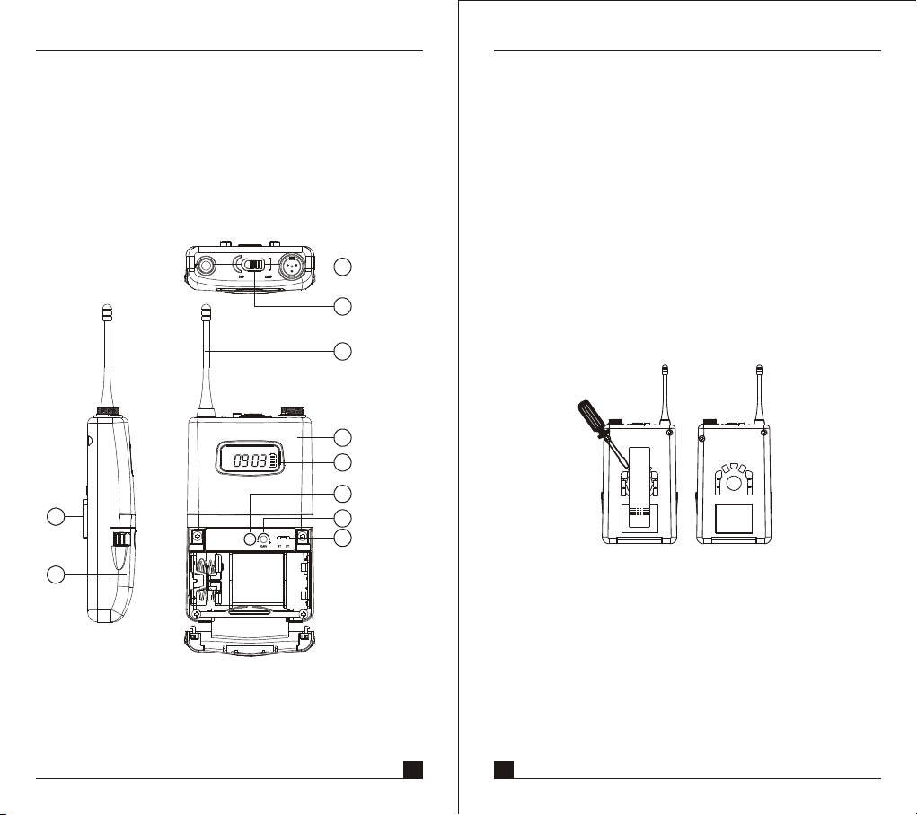
1. PARTS NAME AND FUNCTIONS
1
2
3
4
5
6
7
8
10
BAT
GROUP
CHANNEL
9
3. Transmitting Antenna: 1/ 4 λ transmitting antenna.
4. Transmitter Housing: Packages the PCB and battery.
5. Multi-Function LCD Display
6. ACT Signal Receptor: Receiving ACT signal and
adjusting frequency automatically.
7. Gain Control: Adjusts the desirous input gain.
8. GT/MT Level Selector: Switch to GT position when
under usage of electric guitar or any "Line In" audio.
When connects to a condenser microphone or a
wired microphone, switch to MT position and the
gain control can serve as input sensitivity adjustor.
9. Battery Compartment and Cover: Accommodates
two 1.5V(AA) batteries.
10. Detachable Belt Clip: Allows 360 degrees rotating to
suit transmitting angles. To detach simply use a
screwdriver at a 45 degree angle to unfasten. see
diagram below.
(Fig.1)
1. AF Input Jack: Connects to either a lavaliere or a
headset microphone. (See 5 ways of connection on
AF Input Connections)
2. Power Switch: Switch to ON position for operation.
Switch to OFF position when not in use.
1 2
Page 3
Bodypack Transmitter
Bodypack Transmitter
2. OPERATING INSTRUCTIONS
1. To adjust GT/MT Switch (9), and Gain Control (7),
simply push down both snap locks on the sides of
battery cover and flip it backwards to expose the
adjustment panel.
2. The LED indicator flashes briefly when power on
indicating normal battery status. If no flash occurs it
has either no battery, the battery is drained or installed
incorrectly. Change accordingly.
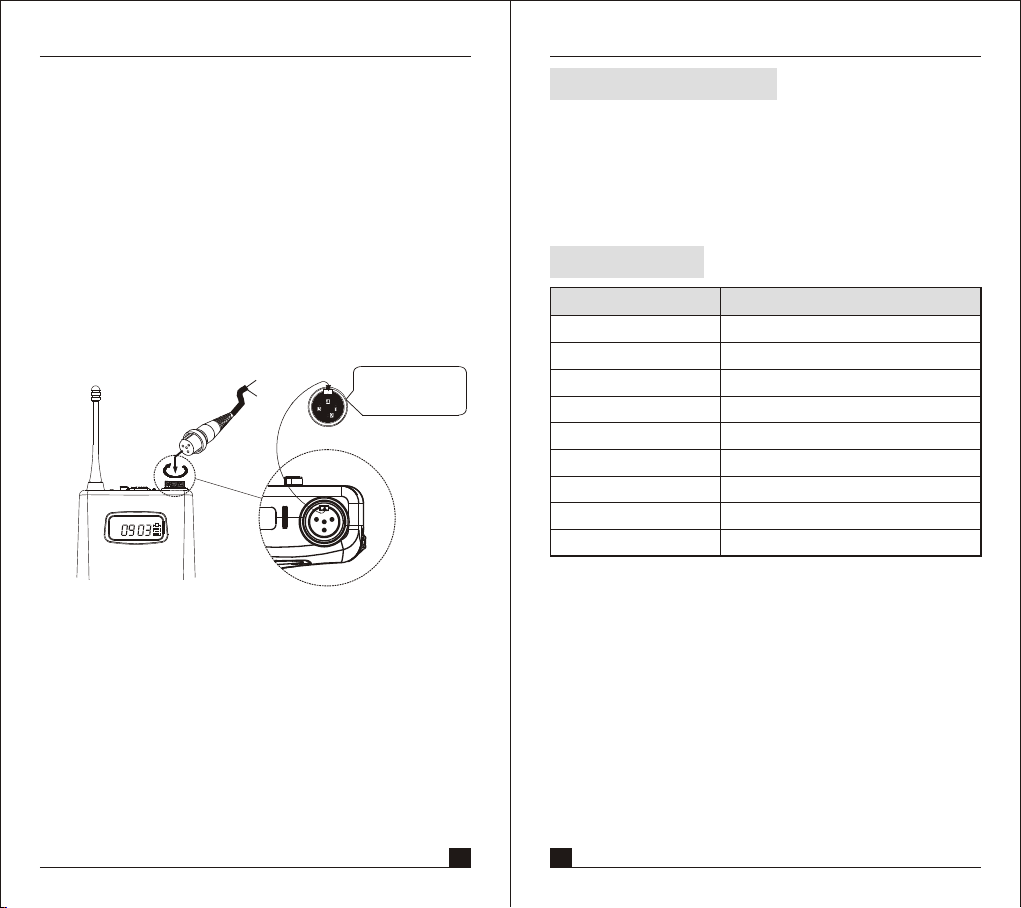
3. Plug the microphone connector into the input jack and
tighten the connector screw clockwise direction as
shown in (Fig. 2).
BAT
GROUP
CHANNEL
on
Capsule Connector
Headset
Lavalier
4
1
3
2
OFF
The ridge on the
connector must match
the indentation on the
socket when inserting.”
(Fig.2)
FURNISHED ACCESSORIES:
AA TYPE BATTERY×2
CARRYING STORAGE BAG×1
INSTRUCTION MANUAL × 1
SPECIFICATIO N:
ITEM
ACT Function
RF Output Power
Oscillation Mode
Spurious Emissions
Maximum Input Level
Microphone Capsule
Battery
Weight (g)
Dimensions (m/m)
SPECIFICATIONS
Yes
10mW (or according to regulations)
PLL Synthesizer
<-55dBc
0dBV
Condenser
AA TYPE × 2
145gs
105×66×25
3
4
Page 4
Bodypack Transmitter
Bodypack Transmitter
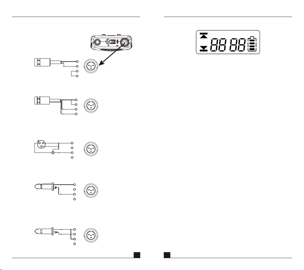
3. AF INPUT CONNECTIONS
(1) 2-Wire Electret condenser
microphone Capsule
PIN
SHIELD
1
AUDIO
(2) 3-Wire Electret condenser microphone Capsule
SHIELD
AUDIO
BIAS
(3) Dynamic Microphone
PIN
2 1
3
SHIELD
AUDIO
(4) Electric Guitar
PIN
SHIELD
AUDIO
(5) Line-in (Impedance 8KΩ ATT. 10dB)
PIN
SHIELD
AUDIO
4
1
3
2
2
3
4
PIN
1
4
2
1
3
2
3
4
1
4
2
1
3
2
3
4
1
4
2
1
3
2
3
4
1
4
2
1
3
2
3
4
4. FUNCTIONS OF LCD DISPLAY
GROUP
CHANNEL
ERR
1. ERR Message: When "ERR" appears, it means
"Operation Error". Please refer to the following codes
to diagnose which error you are experiencing.
ERR no01→EEPROM is not being programmed or
internal data error.
ERR no02→For testing only.
ERR no03→The frequency you are about to program into
the system exceeds microphone's upper limit.
(At this time, microphone is still operatable
and the frequency remains unchanged. To
clear the "ERR" message in LCD display,
simply turn off the power and switch back
ERR no04→The frequency you are about to program into
the system is below microphone's frequency
lower limit. (At this time, microphone is still
operatable and the frequency remains
unchanged. To clear the "ERR" message in
LCD display, simply turn off the power and
switch back on.)
2. "Group" & "Channel " : When both items are shown,
they indicate that the user is currently using the preprogrammed frequency in the receiver.
3. "Channel" Only : If "Channel" is the only item shown in
the display, it indicates the user is using the
personalized frequency. (Such frequency can only be
programmed via MIPRO's ACT Software and available
on ACT-707MC only.)
BAT
5 6
Page 5
Bodypack Transmitter
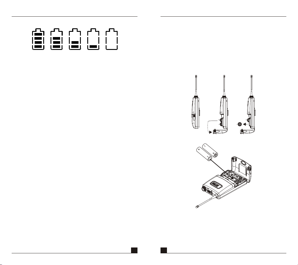
4. Battery Status:
100% 80 % 40% 10% 0%
Battery Status: When the battery has less than 10%
power remaining, batteries must be replaced. If
undervoltage continues, LCD will show "PoFF" and shut
down the system to avoid battery being over-discharged.
5. Switch Off:
When switch the power knob to "Off" position, LCD
will show "PoFF" first. Then, the system is completely
shut down and no further message will be displayed.
Bodypack Transmitter
5. BAT T E RY INSTA L L AT I O N
1. Pushing down both snap locks on the sides of battery
cover to open battery cover. Take out the batteries.
Fig.(3).
2. Insert two 1.5(AA) batteries into the battery
compartment according to the correct polarity as
shown in Fig. (4). Then push up to close the battery
compartment as shown in Fig. (4).
(Fig.3)
7 8
(Fig.4)
PS: When the microphone is not in use:
Make sure the power of the microphone is off. If the
microphone will not be used for some time, please
remove the batteries from the battery compartment to
avoid battery leakage and result in damaged battery
springs and circuit. If a rechargeable battery was
used, take it out and recharge it.
Page 6

THIS DEVICE COMPLIES WITH PART 74 OF THE FCC RULES AND RSS-123 Issue1 OF CANADA.
OPERATION IS SUBJECT TO THE FOLLOWING TWO CONDITIONS: (1) This device may not cause interference. (2) This device must
accept any interference, including interference that may cause undesired operation of the device. This equipment complies with FCC RF
radiation exposure limits set forth for an uncontrolled environment.
 Loading...