

Page 1

ElectronicsCo.,Ltd.
Headoffice:814,Pei-KangRoad,Chiayi,600,Taiwan.
Taipeioffice:5,Lane118,Sung-tehRoad,110,Taipei,Taiwan.
Web-http://www.mipro.com.tw
E-mail:[email protected]
ACT-707TMWirelessMicrophone
ACT-707TMWirelessMicrophone
InstructionManual
2CE160
Page 2
BodypackTransmitter
BodypackTransmitter
Finelycraftedandergonomicallydesigned
ACT-707TMadaptsmagnesiumalloyhousing,
LCDpanel,andhigh-efficienttransmitting
circuitdesignwithlowspuriousshowcases
MIPRO'sprofessionalstyle.
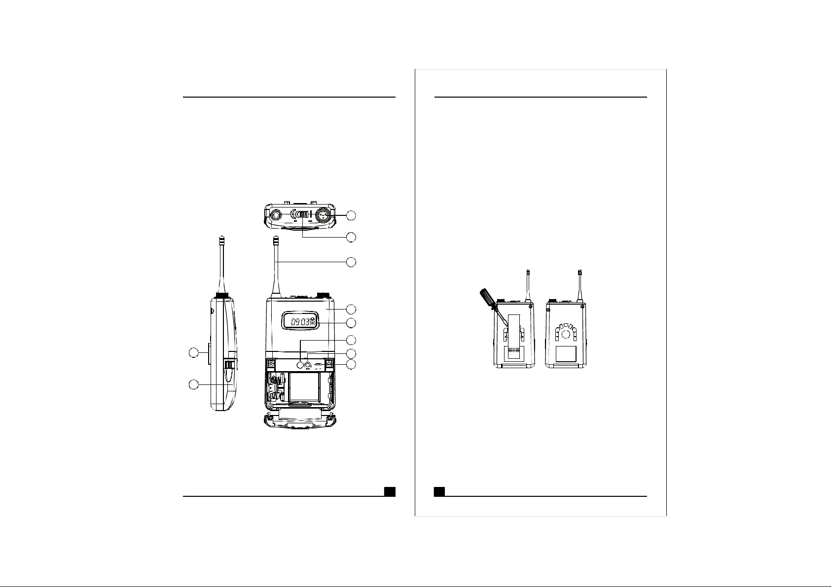
1.PARTSNAMEANDFUNCTIONS
1
2
3
4
5
6
7
8
10
9
GROUP
CHANNEL
BAT
3.TransmittingAntenna:1/4transmittingantenna.
4.TransmitterHousing:PackagesthePCBandbattery.
5.Multi-FunctionLCDDisplay
6.ACTSignalReceptor:ReceivingACTsignaland
adjustingfrequencyautomatically.
7.GainControl:Adjuststhedesirousinputgain.
8.GT/MTLevelSelector:SwitchtoGTpositionwhen
underusageofelectricguitarorany"LineIn"audio.
Whenconnectstoacondensermicrophoneora
wiredmicrophone,switchtoMTpositionandthe
gaincontrolcanserveasinputsensitivityadjustor.
9.BatteryCompartmentandCover:Accommodates
two1.5V(AA)batteries.
10.DetachableBeltClip:Allows360degreesrotatingto
suittransmittingangles.Todetachsimplyusea
screwdriverata45degreeangletounfasten.see
diagrambelow.
λ
(Fig.1)
1.AFInputJack:Connectstoeitheralavaliereora
headsetmicrophone.(See5waysofconnectionon
AFInputConnections)
2.PowerSwitch:SwitchtoONpositionforoperation.
SwitchtoOFFpositionwhennotinuse.
1 2
Page 3
BodypackTransmitter
BodypackTransmitter
2.OPERATINGINSTRUCTIONS
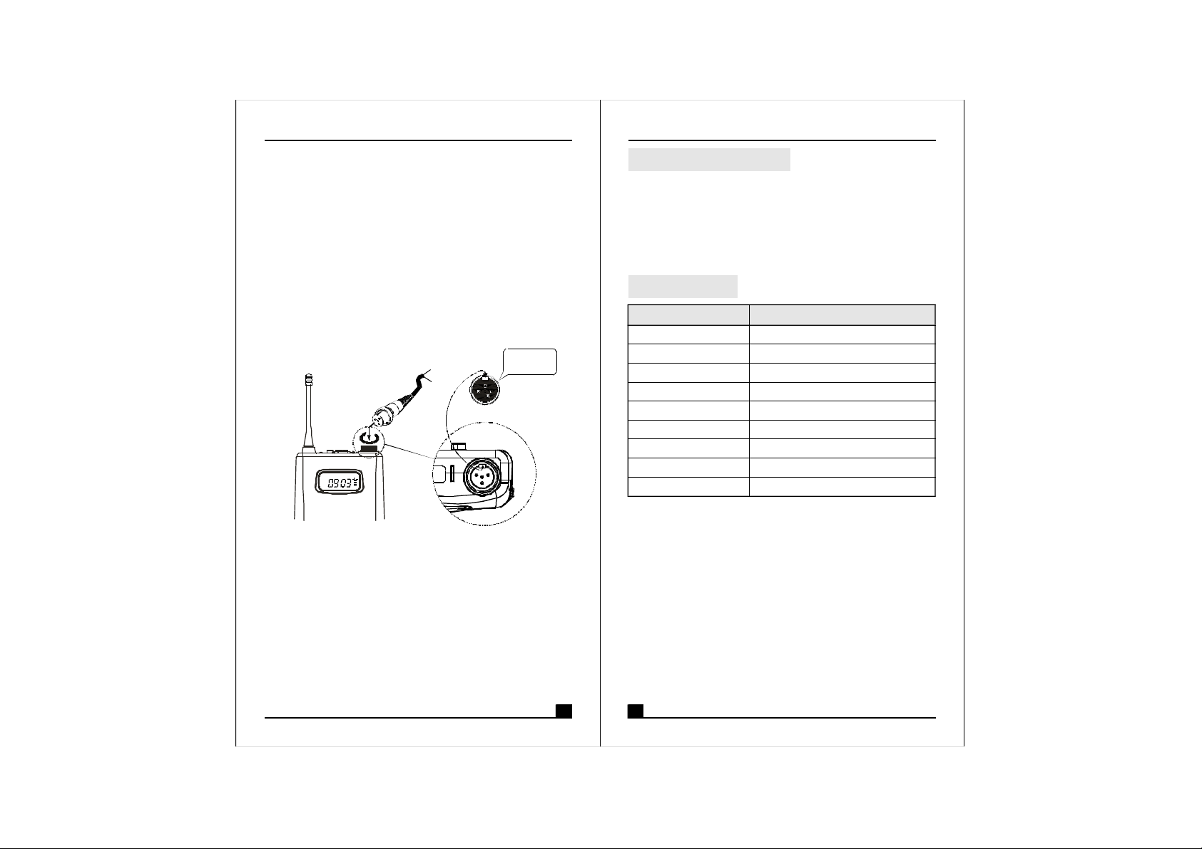
1.ToadjustGT/MTSwitch(9),andGainControl(7),
simplypushdownbothsnaplocksonthesidesof
batterycoverandflipitbackwardstoexposethe
adjustmentpanel.
2.TheLEDindicatorflashesbrieflywhenpoweron
indicatingnormalbatterystatus.Ifnoflashoccursit
haseithernobattery,thebatteryisdrainedorinstalled
incorrectly.Changeaccordingly.
3.Plugthemicrophoneconnectorintotheinputjackand
tightentheconnectorscrewclockwisedirectionas
shownin(Fig.2).
GROUP
CHANNEL
BAT
on
CapsuleConnector
Headset
Lavalier
4
1 3
2
OFF
Pleaseaimofthe
fillisterandinsert
theconnector
(Fig.2)
FURNISHEDACCESSORIES:
①×
AATYPEBATTERY2
②×
CARRYINGSTORAGEBAG1
③×
INSTRUCTIONMANUAL1
SPECIFICATION:
ITEM
ACTFunction
RFOutputPower
OscillationMode
SpuriousEmissions
MaximumInputLevel
MicrophoneCapsule
Battery
Weight(g)
Dimensions(m/m)
SPECIFICATIONS
Yes
10mW(oraccordingtoregulations)
PLLSynthesizer
<-55dBc
0dBV
Condenser
AATYPE2
×
145gs
1056625××
3 4
Page 4
BodypackTransmitter
BodypackTransmitter
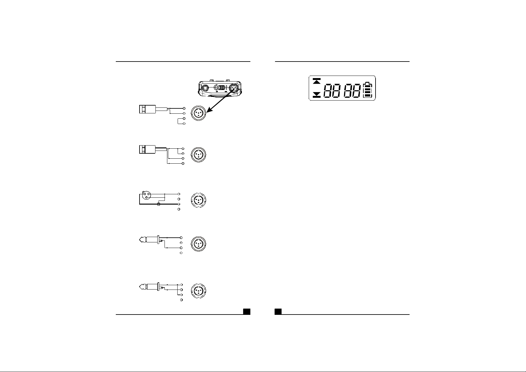
3.AFINPUTCONNECTIONS
(1)2-WireElectretcondenser
microphoneCapsule
PIN
SHIELD
1
AUDIO
(2)3-WireElectretcondensermicrophoneCapsule
SHIELD
AUDIO
BIAS
(3)DynamicMicrophone
PIN
2 1
3
SHIELD
AUDIO
(4)ElectricGuitar
PIN
SHIELD
AUDIO
(5)Line-in(Impedance8KATT.10dB)Ω
PIN
SHIELD
AUDIO
4
1
2
3
2
3
4
PIN
1
4
2
1 3
2
3
4
1
4
2
1
3
2
3
4
1
4
2
1 3
2
3
4
1
4
2
1
3
2
3
4
4.FUNCTIONSOFLCDDISPLAY
GROUP
CHANNEL
ERR
1.ERRMessage:When"ERR"appears,itmeans
"OperationError".Pleaserefertothefollowingcodes
todiagnosewhicherroryouareexperiencing.
ERRno01EEPROMisnotbeingprogrammedor
→
internaldataerror.
ERRno02Fortestingonly.→
ERRno03Thefrequencyyouareabouttoprograminto
→
thesystemexceedsmicrophone'supperlimit.
(Atthistime,microphoneisstilloperatable
andthefrequencyremainsunchanged.To
clearthe"ERR"messageinLCDdisplay,
simplyturnoffthepowerandswitchbackon.)
ERRno04Thefrequencyyouareabouttoprograminto
→
thesystemisbelowmicrophone'sfrequency
lowerlimit.(Atthistime,microphoneisstill
operatableandthefrequencyremains
unchanged.Toclearthe"ERR"messagein
LCDdisplay,simplyturnoffthepowerand
switchbackon.)
2."Group"&"Channel":Whenbothitemsareshown,
theyindicatethattheuseriscurrentlyusingthepreprogrammedfrequencyinthereceiver.
3."Channel"Only:If"Channel"istheonlyitemshownin
thedisplay,itindicatestheuserisusingthe
personalizedfrequency.(Suchfrequencycanonlybe
programmedviaMIPRO'sACTSoftwareandavailable
onACT-707MConly.)
BAT
5 6
Page 5
BodypackTransmitter
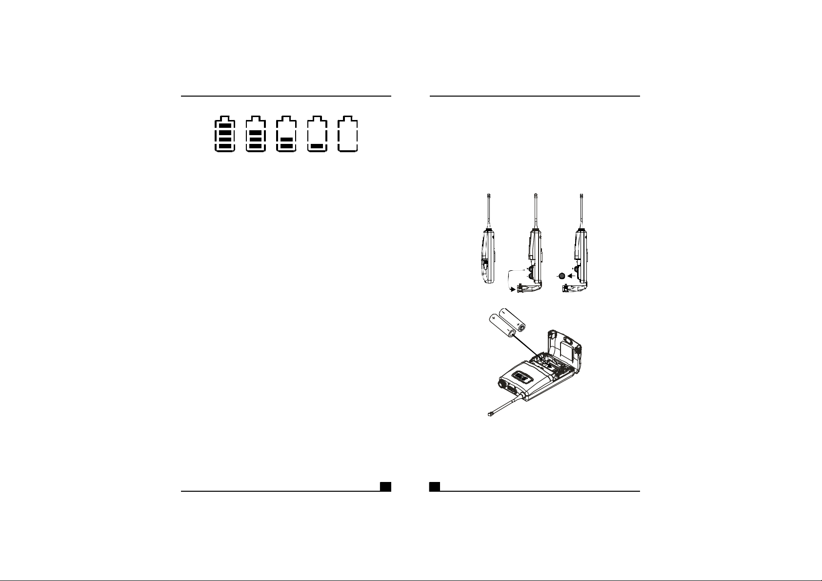
4.BatteryStatus:
100% 80% 40% 10% 0%
BatteryStatus:Whenthebatteryhaslessthan10%
powerremaining,batteriesmustbereplaced.If
undervoltagecontinues,LCDwillshow"PoFF"andshut
downthesystemtoavoidbatterybeingover-discharged.
5.SwitchOff:
Whenswitchthepowerknobto"Off"position,LCD
willshow"PoFF"first.Then,thesystemiscompletely
shutdownandnofurthermessagewillbedisplayed.
BodypackTransmitter
5.BATTERYINSTALLATION
1.Pushingdownbothsnaplocksonthesidesofbattery
covertoopenbatterycover.Takeoutthebatteries.
Fig.(3).
2.Inserttwo1.5(AA)batteriesintothebattery
compartmentaccordingtothecorrectpolarityas
showninFig.(4).Thenpushuptoclosethebattery
compartmentasshowninFig.(4).
(Fig.3)
7 8
PS:Whenthemicrophoneisnotinuse:
Makesurethepowerofthemicrophoneisoff.Ifthe
microphonewillnotbeusedforsometime,please
removethebatteriesfromthebatterycompartmentto
avoidbatteryleakageandresultindamagedbattery
springsandcircuit.Ifarechargeablebatterywas
used,takeitoutandrechargeit.
(Fig.4)
Page 6

BodypackTransmitter
Notice:
Thechangesormodificationsnotexpresslyapproved
bythepartyresponsibleforcompliancecouldvoidthe
user'sauthoritytooperatetheequipment.
IMPORTANTNOTE:
TocomplywiththeFCCRFexposurecompliance
requirements,nochangetotheantennaorthedeviceis
permitted.Anychangetotheantennaorthedevicecould
resultinthedeviceexceedingtheRFexposure
requirementsandvoiduser'sauthoritytooperatethe
device.
NOTE:
9 10
 Loading...