

Page 1
Multi-Interface PC I Bus Serial C ards
RS-232 | RS-422 | RS-485
Non-isolated Models: 3PCIU2, 3PCIU4
Isolated Models: 3PCIOU1, 3PCIOU2
USER MANUAL
Page 2

Multi-Interface PCI Serial Cards
i
Advantech B+B SmartWorx - Americas
707 Dayton Road
Ottawa, IL 61350 USA
Phone (815) 433-5100
Fax (815) 433-5105
Advantech B+B SmartWorx - European Headquarters
Westlink Commercial Park
Oranmore, Co. Galway, Ireland
Phone +353 91-792444
Fax +353 91-792445
www.advantech-bb.com
ADVANTECH B +B SMARTWORX TECHNICAL SUPPORT
USA/Canada: 1 (800) 346-3119 (Ottawa, IL USA location)
(Monday - Friday, 7:00 a.m. to 7:00 p.m. CST)
Europe: +353 91 792444 (Ireland location)
(Monday - Friday, 8 a.m. to 5:00 p.m. GMT)
Email: support@advantech-bb.com
Web: www.advantech-bb.com
Page 3

Multi-Interface PCI Serial Cards
ii
TABLE OF CONTENTS
1.GENERAL INFORMATION ........................................................................ 1
Introduction ................................................................................................ 1
Features .................................................................................................... 1
Optically Isolated Models & Features ........................................................ 2
Non-isolated Models & Features ............................................................... 2
Specifications ............................................................................................ 3
2. SERIAL CARD SETUP .............................................................................. 4
Pre-Setup Steps ........................................................................................ 4
ESD Precautions ................................................................................... 4
Initial Configuration ................................................................................ 4
Overview of Operational Modes ................................................................ 5
RS-232 Mode ........................................................................................ 5
RS-422 Mode ........................................................................................ 5
RS-485 Mode ........................................................................................ 5
Operating Mode Selection ......................................................................... 6
Setting the DIP Switches on RS-232/422/485 Ports .............................. 6
Setting the DIP Switches on RS-422/485 Only Ports ............................ 7
Installing the Serial Card ........................................................................... 8
3. DRIVER SOFTWARE INSTALLATION ..................................................... 9
INSTALLING WINDOWS 7 DRIVER SOFTWARE .................................... 9
INSTALLING WINDOWS XP DRIVER SOFTWARE ................................. 9
Pre-Installation Steps ............................................................................ 9
Using the Found New Hardware Wizard ............................................. 10
PCI Card Software Installation ............................................................ 10
Checking the Driver Installation ........................................................... 10
4. SETTING DRIVER OPTIONS ................................................................. 11
CONFIGURING PORT SETTINGS ......................................................... 11
SETTING THE FIFO BUFFERS .............................................................. 12
SETTING THE RTS CONTROL PARAMETER ....................................... 13
SETTING THE HARDWARE HANDSHAKING LEVEL ............................ 13
CHANGING THE COM PORT NAME/NUMBER ..................................... 13
Page 4

Multi-Interface PCI Serial Cards
iii
5. REMOVING DRIVERS, PORTS, CARDS ............................................... 15
WINDOWS 7 ........................................................................................... 15
Uninstalling the MIport Card ................................................................ 15
Uninstalling the COM ports .................................................................. 15
Removing INF and PNF Driver Files ................................................... 15
6. RS-232 CONNECTIONS/OPERATION ................................................... 18
RS-232 Mode .......................................................................................... 18
RS-232 Signal Designations ad DB9 Pinouts .......................................... 18
RS-232 Signal Designations ................................................................ 19
DTE and DCE .......................................................................................... 19
RS-232 Signal Levels .............................................................................. 19
Handshaking ........................................................................................... 20
RTS Control In RS-232 Mode .................................................................. 20
7. RS-422/485 CONNECTIONS/OPERATION ............................................ 21
RS-422/485 Mode ................................................................................... 21
RS-422/485 Signal Designations and DB-9 Pinout ................................. 21
RS-422/485 Signal Designations ......................................................... 21
RS-422/485 Differential Signals .............................................................. 21
RS-422 Operation ................................................................................... 22
RS-422 Limitations .............................................................................. 22
RS-485 Operation ................................................................................... 23
Send Data Control ............................................................................... 23
RS-485 Termination Resistors ................................................................ 24
RS-485 Network Biasing ......................................................................... 25
2-Wire R S-485 Connections .................................................................... 26
2-Wire R S-485 Mode ........................................................................... 26
4-Wire R S-422 and RS-485 Connections ................................................ 27
RS-422 Point to Point Connection ....................................................... 27
RS-422 Point to Multipoint Connection ................................................ 27
4-Wire R S-485 Connection .................................................................. 28
8. TROUBLESHOOTING MIPORT PCI CARDS ......................................... 29
Starting Up .............................................................................................. 29
Checking Connections ............................................................................. 29
RS-232/422/485 Operation .................................................................. 29
Page 5

Multi-Interface PCI Serial Cards
iv
RS-232 Operation ............................................................................... 29
RS-422/485 Operation......................................................................... 29
Checking the MIport Card ........................................................................ 30
Appendix A. DIP Switch/Mode Settings ....................................................... 32
DIP Switch 1 (RS-232/422/485 ports).................................................. 32
DIP Switch 2 (RS-232/422/485 ports).................................................. 32
DIP Switch 3 (RS-232/422/485 ports).................................................. 33
Setting DIP Switches on RS-422/485 Only Ports .................................... 33
DIP Switch 1 (RS-422/485 only) .......................................................... 33
DIP Switch 2 (RS-422/485 only) .......................................................... 34
Appendix B. CONNECTOR PINOUTS ........................................................ 35
RS-232 Pinouts ....................................................................................... 35
RS-422/485 Pinouts ................................................................................ 36
Appendix C. TROUBLESHOOTING WITH COMTEST ............................... 37
ComTest Features ................................................................................... 37
Installing ComTest ................................................................................... 37
Loopback Testing with ComTest ............................................................. 38
ELECTROSTATIC DISCHARGE PRECAUTIONS ...................................... 39
Page 6

Multi-Interface PCI Serial Cards
v
FCC RADIO FR EQUENCY INT ERFERENC E STATEMENT
This equipment has been tested and found to comply with the limits for a Class B
computing device, pursuant to Part 15 of the FCC Rules. These limits are
designed to provide reasonable protection against harmful interference when the
equipment is operated in a commercial environment. This equipment generates,
uses and can radiate radio frequenc y energy and, if not installed and used in
accordance with the instruction manual, may cause harmful interference to radio
communications. Operation of this equipment in a residential area is likely to
cause harmful interference in which the user will be required to correct the
interference at his/her own expense.
Any changes or modifications not expressly approved by the manufacturer could
void the user’s authority to operate the equipment.
The use of non-shielded I/O cables may not guarantee compliance with FCC RFI
limits. This digital apparatus does not exceed the Class B limits for radio noise
emission from digital apparatus set out in the Radio Interference Regulation of
the Canadian Department of Communications.
Le présent appareil numérique n’ém et pas de bruits radioélectriques dépassant
les limites applicables aux appareils numériques de classe B prescrites dans le
Règlement sur le brouillage radioélectrique publié par le ministère des
Communications du Canada.
Page 7

Multi-Interface PCI Serial Cards
vi
WARRANTY
Effective for products of B+B SmartWorx shipped on or after May 1, 2013, B+B
SmartWorx warrants that each such product shall be free from defects in material and
workmanship for its lifet ime. This limit ed lifetime warr anty is applicable solely to the
original user and is not transferable.
This warrant y is expressly conditioned upon proper storage, installati on, connection,
operation and mai ntenance of products in acc ordance with thei r written specifications.
Pursuant to the w arranty, wit hin the warranty per iod, B+B SmartWorx, at its option
will:
1. Replace the pr oduct with a f unctional equivalent;
2. Repair the product; or
3. Provide a par tial refund of purchase pric e based on a depreciated value.
Products of other manufacturers sold by B+B SmartWorx are not subject to any
warranty or indemnity offered by B+B SmartWorx, but may be subject to the
warranties of the other manufacturers.
Notwithstandi ng t he f oregoing, under no circumstances shall B+B Sm artWorx have any
warranty obligat ions or any other liability for: (i) any defects resulti ng from wear and tear,
accident, improper use by the buye r or use by any third party ex cept in accordanc e with the
written instructions or advice of t he B+B SmartWorx or t he manufacture r of the p roducts,
including without limitation surge and overvoltage c onditions that ex c eed specified rat ings, (ii)
any products which have been adj usted, modifi ed or repaired by any pa rt y other than B+B
SmartWorx or (iii) any descriptions, illustrations , fi gures as t o performanc e, drawings and
particulars of weights and dimensions contained in the B+B Smart W orx’ catalogs, pric e lists,
marketing materials or elsewhe re s ince they are merel y int ended to represent a general idea of
the products an d do not form part of thi s pric e quote and do not c ons t it ut e a w arranty of any
kind, whether express or impli ed, as to any of t he B+B SmartWorx’ products.
THE REPAIR OR REPLACEMENT OF THE DEFECTIVE ITEMS IN ACCORDANCE WITH
THE EXPRESS WARRANTY SET FORTH ABOVE IS B+B SMARTWORX’ SOLE
OBLIGATION UNDER THIS WARRANTY. THE WARRANTY CONTAINED IN THIS SECTION
SHALL EXTE N D TO THE ORIGINAL USER ONLY, IS IN LIEU OF ANY AND ALL OTHER
WARRANTIES, EXPRESS OR IMPLIED, AND ALL SUCH WARRANTIES AND INDEMNITIES
ARE EXPRESSLY DISCLAIMED, INCLUDING WITHOUT LIMITATION (I) THE IMPLIED
WARRANTIES OF FITNESS FOR A PARTICULAR PURPOSE AND OF MERCHANTABILITY
AND (II) ANY WARRANTY THAT THE PRODUCTS ARE DO NOT INFRINGE OR VIOLATE
THE INTELLECTUAL PROPERTY RIGHTS OF ANY THIRD PARTY. IN NO EVENT SHALL
B+B SMARTWORX BE LIABLE FO R L OSS OF BUSINESS, LOSS OF USE OR OF DATA
INTERRUPTION OF BUSINESS, LOST PROFITS OR GOODWILL OR OTHER SPECIAL,
INCIDENTAL, EXEMPLARY OR CONSEQUENTIAL DAMAGES. B+B SMARTWORX SHALL
DISREGARD AND NOT BE BOUND BY ANY REPRESENTATIONS, WARRANTIES OR
INDEMNITIES MADE BY ANY OTHER PERSON, INCLUDING WITHOUT LIMITATION
EMPLOYEES, DISTRIBUTOR S, RESELLERS OR D EALERS OF B+B SMARTWORX WHICH
ARE INCONSISTENT WITH THE WARRANTY, SET FORTH ABOVE.
Page 8

Multi-Interface PCI Serial Cards
1
1.GENER AL INFORMATION
INTRODUCTION
MIport PCI serial interface cards allow you to add RS-232, RS-422 and RS-485
interfaces to Windows based computers equipped with a PCI bus. Depending on
your choice of card one or two optically isolated serial ports, or two or four nonisolated serial ports, can be added. MIport PCI serial cards are Plug and Play
compatible, which allows the Windows Operating System and driver to set the
addresses and IRQ us ed by the card.
FEATURES
• Optically isolated or non-isolated models available
• Isolated models available in 1 or 2 ports
• Non-isolated models available in 2 or 4 ports
• 4 port model includes fan-out cables
• Plug & play compatible – Windows sets addresses and IRQ used
• 5 Volt and 3.3 Volt PCI bus compatible
• PCI-X compatible
• Conform to the PCI V2.3 Universal PCI specification
• RS-232/RS-422/RS-485 interfaces
• 2-wire or 4-wire RS-485 operation (half or full-duplex)
• Automatic Send Data Control for RS-485 operation
• Buffered high speed XR17D15x PCI Bus UARTs (16C550 compatible) with 64
byte FIFOs for input/output with programmable trigger thresholds
• Advanced driver function for COM port rename (refer to Chapter 4)
• Supports baud rates up to 460.8 kbps
• Windows XP, 2008 Server (32/64 bit), Vista (32/64 bit), 7 (32/64 bit)
Page 9
Multi-Interface PCI Serial Cards
2
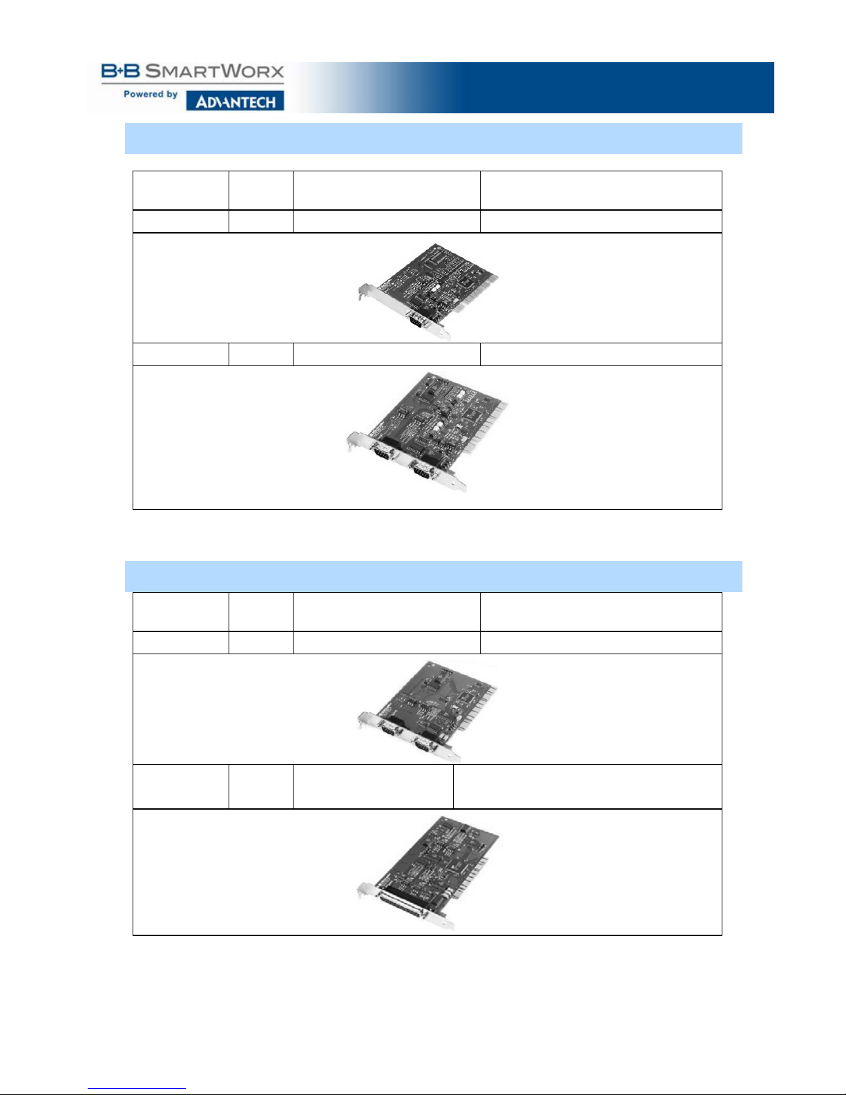
OPTICAL LY ISOLAT ED MODELS & FEATURE S
Model
Number
Ports Interface Connectors
3PCIOU1
1
RS-232/422/485
DB-9 male
3PCIOU2
2
RS-232/422/485
DB-9 male
Figure 1: MiPort Optically Isolated PCI Serial Interface Cards
NON-ISO LATED MO DELS & F EATURES
Model
Number
Ports Interface Connectors
3PCIU2
2
RS-232/422/485
2 x DB-9 male
3PCIU4
4 RS-232/422/485 DB-37 female
(plus DB-37 to 4x DB-9 male cable)
Figure 2: MiPort Non-isolated PCI Serial Interface Cards
Page 10

Multi-Interface PCI Serial Cards
3
SPECIFICATIONS
OS Supported
Windows XP, 2008 Server (32/64 bit), Vista (32/64 bit), 7
(32/64 bit)
Bus
Slot
PCI Bus (33MHz/32-bit) PCI Bus Specification.
Requires one PCI slot (3.3V or 5V signaling).
Baud Rates
Maximum: Up to 460.8 kbps (RS-232/422/485)
Typical: 75, 110, 134, 150, 300, 600, 1200, 1800, 2400,
4800, 7200, 9600, 14.4k, 19.2k, 38.4k, 57.6k, 115.2k,
230.4k, 460.8k
UARTs
XR17D15x (16C550 compatible) with 64 byte FIFO buffers
Character Length
Parity
Stop Bits
5, 6, 7 or 8 bits.
Even, odd, none, space or mark.
1, 1.5 or 2.
Optical Iso lation
(3PCIOU1,
3PCIOU2 only)
2000 VDC minimum on all lines.
Ports are isolated from the PC power and ground, as well as
other ports on the same card.
Connectors
3PCIOU1: 1 – DB-9 male
3PCIOU2: 2 – DB-9 male
3PCIU2: 2 – DB-9 male
3PCIU4: 1 – DB-37 female w/ DB-37 to 4 x DB-9 male cable
Data Signals
RS-232: TD, RD, RTS, CTS, DTR, DSR, DCD, RI and GND
(TD, RD, RTS, CTS, GND only on 3PCIOU4)
RS-422: TD(A)-, TD(B)+, RD(A)-, RD(B)+ and GND
RS-485: Data(A)-, Data(B)+ and GND
Environmental
Operating temperature range: 0 to 50 ºC minim um.
Operating humidity: 5% to 95%, non-condensing.
Dimensions
4.8 x 3.8 in (12.2 x 9.6 cm) card edge.
(Mounting bracket, 1.2 x 12.1 x 0.9 cm).
Accessories
Software: Driver CD-ROM disc for Windows XP
(32-bit/64-bit), Vista (32-bit /64-bit), 7 (32-bit /64-bit), Server
2003 (32-bit /64-bit), Server 2008 (32-bit /64-bit), Server 2008
R2 (64-bit)
Manual: Instruction Manual - on CD ROM.
Figure 3: MiPort Serial Card Specifications
Page 11
Multi-Interface PCI Serial Cards
4
2. SERIAL CAR D SETUP
The following Serial Card Setup section applies to these PCI cards:
• 3PCIOU1 - one-port, optically isolated PCI serial card
• 3PCIOU2 - two-port, optically isolated PCI serial card
• 3PCIU2 - two-port, non-isolated PCI serial card
• 3PCIU4 - four-port, non-isolated PCI serial card
Any deviations from the procedure for specific models are noted.
PRE-SETUP STEPS
Your serial card has been tested for proper operation before packaging and
shipping. It should be in perfect mechanical and electrical condition upon receipt.
ESD PRECAUT IONS
To ensure a successful installation and setup it is important that you follow the
standard ESD precautions outlined below:
CAUTION:
This is an Electrostatic Sensitive Device.
Use ESD precautions for safe handling.
Before removing the card from the anti-static protective packaging:
• Discharge any static electricity buildup on your body by touching a
large grounded metal surface or the metal chassis on equipment
connected to earth ground by a 3-wire power cord. Use of a
grounding wrist strap is recommended.
• Avoid touching the gold connectors or other parts on the card except
when necessary to set the configuration DIP switches.
• Remove AC power from the computer before inserting the card.
INITIAL CONFIGURATION
The ports in your MIport card are normally pre-configured for RS-232 operation. To
ensure the card is configured correctly for your desired operating mode, you must
check and/or set the three operating mode DIP switches on the card. If you are
configuring for RS-485 Mode you also may have to set up the RTS Control
parameter in the device driver.
NOTE: For information on Setting Driver Options, refer to Chapter 4.
Page 12

Multi-Interface PCI Serial Cards
5
OVERVI EW OF O PERATIONAL MODES
RS-232 MODE
In RS-232 Mode, MIport seri al ports function as buffered standard PC serial ports and
operate as DTEs (Data Terminal Equipment). RS-232 interfaces are commonly us ed for
communications with modems , serial printers, and computer controlled devi ces such as
securit y equipment, bar code scanners and point-of-sale devices.
For most MIport models, RS-232 Mode supports eight single-ended signal lines and
Signal Ground (GN D ) including Tr ansmit (TD), Receive (RD) and s ix hardware
handshake lines (DTR, DSR, RTS, CTS, DCD, RI).
RS-422 MODE
In RS-422 Mode, MI port serial ports provide two s ets of differential signal pair s (TD and
RD) and Signal Gr ound for each port . The RS-422 standard uses balanced di fferential
drivers and receivers for each signal. This facilitates greater communication distances
than unbalanc ed systems suc h as R S -232. In RS-422 mode, the transmit ter and receiver
are always enabl ed (TX ON, RX ON).
RS-422 operation i s suitable f or interconnecting a computer and one device for f ull duplex
(point-to-point) bi-directional communication, or a computer and several devic es for
unidirectional (point-to-multi-points) communication. RS-422 interfaces are commonl y
used for video editing/control, camera control, electronic signage, television
studio/satellite dish control, performance lighting and audio equipment control.
RS-485 MODE
In RS-485 Mode, MIport cards provide RS-485 interfaces which operate with the same
signals and s ignal levels as RS -422. R S-485 interfaces differ from RS-422 in that they
allow multiple devices to share the same communi cation link using half duple x (2-wire) or
full duplex (4-wire) connections. Since it is possible to have mor e than one transmitter
connected to the media, transmitters must be enabled only while sending data, and tristated at all other times so other devices can use the wire pair . MIport cards aut om atically
enable the tr ansmitter at the appropriate t ime using Automat ic Send Data Control, based
on the contents of the output buffer. When the buffer has data to send, the transmitter is
enabled (TX SD). When all data i n the buffer has been s ent, the trans m itter is disabled
and tri-st ated to a high impedance state.
In half-duple x operation, the receiver is di sabled during transmit (RX ), and enabled
when not transmitting. In f ull-duplex operati on the receiver i s always enabled (RX O N ).
Since RS-485 transmitters are tri-stated when not transmitting, the receive inputs must be
biased to ensur e the media float s in the Mark stat e so that the first Space state is
detected cor rectly at the start of the next transmission.
These serial cards incorporate the necessary biasing to accommodate up to 32 standard
nodes. (Typical input resistance (Rin) for each load is 12kΩ). Provisions are made for
custom biasing and/or term ination.
NOTE: For more information on RS-485 Mode, refer to Chapter 7.
Page 13
Multi-Interface PCI Serial Cards
6
OPERATING MODE SELECTION
The hardware address and IRQ for the serial card is set by the Windows Operating
System using driver information files and the Plug and Play OS.
The Operating Mode is set using DIP switches, Device Manager Driver Settings and
by your cable connections and software. Each port on a MIport card has an
associated DIP switch to set its operating mode. The port number associated with
the DIP switch is clearly silk-sc reened on the print ed circ uit b oar d.
NOTE: For DIP Switch locations on card models, refer to Appendix A.
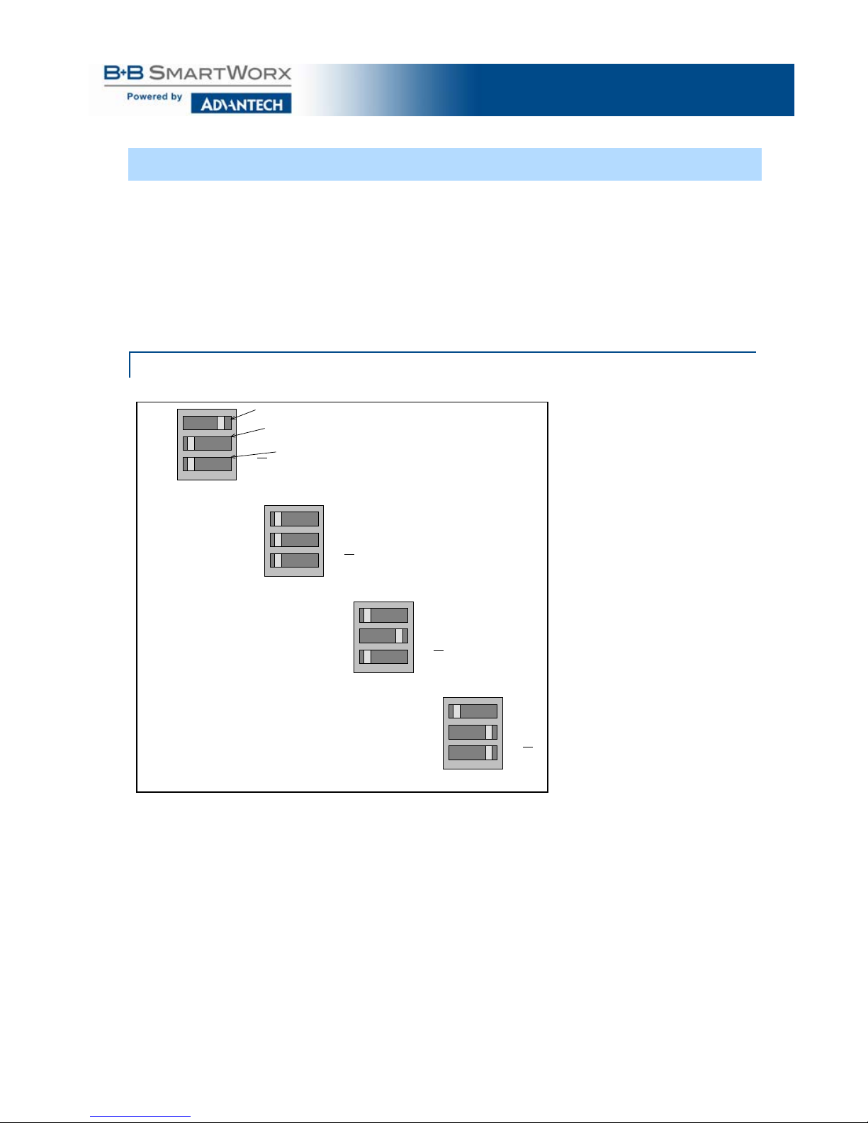
SETTI NG THE DIP SW ITCHES ON RS-232/422/485 PORTS
Set the DIP switches to configure the desired operating mode as follows:
422/485
TX On
RX On
232
TX SD
RX SD
Switch 1
Switch 2
Switch 3
RS-232 Mode
422/485
TX On
RX On
232
TX SD
RX SD
RS-422 Mode
422/485
TX On
RX On
232
TX SD
RX SD
4-wire RS-485 Mode
422/485
TX On
RX On
232
TX SD
RX SD
2-wire RS-485 Mode
Figure 4: RS-232/422/485 DIP Switch Settings
DIP Switch 1 (RS-232/422/485 Ports)
The top DIP switch (1) configures the port for RS-232 or RS-422/485 operation. This
switch is the only one that is required to be set for RS-232 operation. The positions of
switches 2 and 3 do not matter when switch 1 is set for RS-232 operation.
DIP Switch 2 (RS-232/422/485 Ports)
The middle DIP switch (2) configures the port for RS-4 85 or RS -422 operat ion. For
RS-422 operation (which uses two wire pairs and sends point-to-point or point-tomulti-points) the transmitter can be enabled all the time. Placing the middle DIP
switch in the TX ON position accomplishes this.
Page 14

Multi-Interface PCI Serial Cards
7
For RS-485 operation, the middle DIP switch is placed in the TX SD position. In this
position the transmitter is only enabled when data is being sent. The transmitter is
tri-stated when not sending data, allowing other transmitters on the communications
line to transmit without interference.
DIP Switch 3 (RS-232/422/485 Ports)
The bottom DIP switch (3) configures the port for half-duplex (two-wire) RS-485
operation or full-duplex (four-wire) RS-422/RS-485 operation. Placing the bottom
DIP switch in the RX ON position configures the port for four-wire operation. In this
mode the receiver is continuously enabled, allowing it to receive all data on the
communications line. Since the transmitter sends data on the other wire pair, the
port does not receive its own transmissions.
Placing the bottom DIP switch in the RX position configures the port for two wire
operation. In this mode the transmitter and receiver are connected to the same wire
pair. The receiver is disabled when its transmitter is sending, preventing the port
from receiving its own data.
SETTING THE DIP SWITCHES ON R S-422/485 ONLY PORTS
Ports that do not inc lude RS-232 operation use double DIP switches rather than
triple DIP switches. These DIP switches operate the same as the two bottom DIP
switches in the RS-232/422/485 ports.
DIP Switch 1 (RS-422/485 Only)
The top DIP switch (1) configures the port for RS-485 or RS-422 operation. For RS422 operation (which uses two wire pairs and sends point-to-point or point-to-multipoints), the transmitter can be enabled all the time. Placing the middle DIP switch in
the TX ON position accomplishes this.
For RS-485 operation the middle DIP switch is placed in the TX SD position. In this
position, the transmitter is only enabled when data is being sent. The transmitter is
tri-stated when not sending data, allowing other transmitters on the communications
line to transmit without interference.
DIP Switch 2 (RS-422/485 Only)
The bottom DIP switch (2) configures the port for half-duplex (two-wire) RS-485
operation or full-duplex (four-wire) RS-422/RS-485 operation. Placing the bottom
DIP switch in the RX ON position configures the port for four-wire operation. In this
mode the port’s receiver is continuously enabled, allowing it to receive all data on
the communications line. Since the port’s transmitter sends data on the other wire
pair the port does not receive its own transmissions.
Placing the bottom DIP switch in the RX position configures the port for two-wire
operation. In this mode, the port’s transmitter and receiver are connected to the
same wire pair. The receiver is disabled when its transmitter is sending, preventing
the port from receiving its own data.
Page 15

Multi-Interface PCI Serial Cards
8
INSTAL LING TH E SERIAL C ARD
CAUTION:
This is an Electrostatic Sensitive Device.
Use ESD precautions for safe handling.
Before removing the card from the anti-static protective packaging:
• Discharge any static electricity buildup on your body by touching a
large grounded metal surface or the metal chassis on equipment
connected to earth ground by a 3-wire power cord. Use of a
grounding wrist strap is recommended.
• Avoid t ouchi ng the gold connectors or other parts on the card except
when necessary to set the configuration DIP switches.
• Remove AC power from the computer before inserting the card.
1. Shut down your computer.
2. Unplug the power cord to remove power to prevent accidentall y turning on the
computer during installation.
3. Remove the cover of the c omputer.
4. Locate an empty PCI expans ion slot.
5. Remove the expansion slot cover. Save the retaining screw.
6. Ground yourself to the computer chassis before and while i nserting the card.
7. Install the card into the unused slot. Be certain that the card is inserted
completely (fully seated) in the slot.
8. Secure the card with the mounting screw from Step 5.
9. Replace the cover; plug in the power cord.
10. Connect your cables.
11. Power up the system.
12. Install the drivers as described in Chapter 3.
Page 16

Multi-Interface PCI Serial Cards
9
3. DRIVER SO FTWARE INSTALLATION
INSTAL LING W INDOWS 7 DR IVER SOFTW ARE
Windows 7 does not have a “Found New Hardware Wizard.” Therefore the MIPort
Driver must be installed manually.
1. Install the MIPort Card and place the CD in the CD ROM Drive.
2. Open Device Manager.
3. PCI Serial Port will be listed under “Other Devices.”
4. Select PCI Serial Port, right click, and select “Update Driver.”
5. Select “brows my computer” and locate the drivers on the CD ROM.
6. A windows security notice will be displayed. Select “install.” This notice will be
displayed again. Select “install.”
7. “Windows successfully updated driver software” will be displayed. Selec t
close.
8. In device manager, the MIPort Card will be listed under Multiport Serial
Adapter. Additional COM Ports will be listed under “Ports (COM & LPT).”
INSTAL LING W INDOWS XP DRIVER SOFTW ARE
Installation of the MIport driver software on Windows XP is a three-step process:
1. Windows XP searches and identifies new hardware that has been installed.
2. Use the Found New Hardware Wizard to install the driver software for the
card.
3. You use the Found New Hardware Wizard to install the software for each port
on the card.
There are several possible methods for installing the software. The procedure
outlined here is recommended for most situati ons.
NOTE: If, at some point in the future, you want to update these
drivers, remove the old drivers before installing the new
version. Refer to Chapter 6 for driver removal procedures.
PRE-INST ALLATION STEPS
1. Configure the port(s) on the card for the desired mode (RS-232, RS-422 or
RS-485) using the three DIP switches on the card.
2. If configuring for RS-422 or RS-485 Modes, and bias or termination resistors
are needed, add them at this time.
NOTE: For information on DIP switch settings and
bias/termination resistors, refer to Chapter 2.
3. Install the card in the slot. Use appropriate ESD handling precautions.
4. Power up the computer.
5. Insert your driver disc in the CD-ROM drive.
Page 17

Multi-Interface PCI Serial Cards
10
USING THE FO UND NEW HARDWARE W IZARD
Windows will detect the PCI card and start the Found New Hardware Wizard to
begin the driver installation. Driver software (on CD-ROM) is provided with your
MIport card. Do not connect to Windows Update to search for software.
1. Select No, not at this time and click Next.
PCI CARD SOFTW ARE INSTALLATION
Once the new hardware has been detected, the wizard will proceed to install the
software for the card. The following dialog box will appear:
1. To begin the installation of the software for the PCI card, click Install the
software automatically. Click Next.
2. Windows will find the appropriate files on the CD, then display a dialog box
concerning Window Logo testing for Vista. This feature of Vista simply
indicates that these drivers have not yet undergone the Microsoft testing
procedure required to use the Windows Vista Logo on the packaging. Diver
compatibility is not affected .
3. Click Continue Anyway.
4. A dialog box will appear indicating the software installation is proceeding.
5. When the Completing the Found New Hardware Wizard dialog appears,
click Finish.
Port Driver Installation
The Welcome to the Found New Hardware Wizard will appear again, indicating it
has detected a port on the PCI card. Repeat the steps above to install the port driver
software.
If the cared you are installing has more than one port, Windows Vista will find each
port in sequence and re-launch the Found New Hardware Wizard for each port.
Repeat the previous steps for each port.
CHECKING T HE DRIVER INSTALLATION
You may want to check to verify that the new B+B COM ports are now available.
1. From the Widows Desktop, click Start → Control Panel →System and
Maintenance→ Device Manager
2. In the Device Manager, click Multi-port serial adapters. All serial adapter
cards should appear in the list. Additional information about the cards can
be obtained by double-clicking the name of the card.
3. Click Ports (COM & LPT) All installed ports should appear in the list. The
COM port number assigned to each port will be shown.
Page 18

Multi-Interface PCI Serial Cards
11
4. SET TING DRI VER OPT IONS
CONFIGURING PORT SETTINGS
By entering the Properties dialog a variety of information can be obtained and
several port parameters can b e config ured.
1. On the Ports (COM & LPT) list, double-c lick the name of the port to be
configured.
2. On the Port Properties dialog, c lick the P ort Settings tab.
The dialog will display the current settings for Bits per second, Data
bits, Parity, Stop bits and Flow control. If necessary, change these
settings to the required values.
Figure 5: Port Setting Dialog
3. Click Advanced…
The Advanced Port Settings dialog will appear. This screen allows
you to set the Receive and Transmit FIFO buffer thres holds, RTS
Control parameters, Hardware handshaki ng hysteresis level and the
COM port name.
Page 19

Multi-Interface PCI Serial Cards
12
Figure6: Advanced Port Settings
SETTING THE FIFO BUFFERS
MIport cards use UARTs that contain 64-byte transmit and receive FIFO (first in, first
out) buffer registers. The transmit buffer holds the data to be sent; the receive buffer
holds the data received.
Transmit Buffer: Lo w parameter in the Advanced Port Settings dialog allows you
to set the minimum value at which the UART will request more data from the
computer. As the MIport card is transmitting data, the number of bytes left in the
transmit buffer will decrease. When the buffer reac hes the value set, the UART will
request more data from program memory. This is intended to optimize the
throughput of the data. Typically this parameter is set at zero and usually does not
have to be changed.
Receive Buffer: Low parameter in the Advance Port Settings dialog allows you to
set the value at which the UART will request that the computer read the data that
has been received. As the MIport card is receiving data the contents of the receive
buffer increases, when it reaches the value set, the UART will request that the
computer transfer the contents of the buffer to program memory. This is intended to
optimize the throughput of the data. The default value is 14. Usually this parameter
does not have to be c hanged.
Page 20

Multi-Interface PCI Serial Cards
13
SETTING THE RTS CONTROL P ARAMETER
1. Set RTS Control to Normal for RS-232; set RTS Control to RS-485 Mode for
2-wire or 4-wire RS-485 operation. Either setting can be used for RS-422.
Typically the COM parameters set in this dialog box are overridden by the
software application.
Note: For proper operati on the DIP switches on the PCI card must be
set for the same mode. Refer to Chapter 2 for more information on
configuring the DIP switches.
2.
The Direction Control Delay (bit times) box allows you to set the length of
time the Transmit driver continues to be enabled after the last bit of data in the
transmit register has been sent. The purpose of this setting is to mai ntain the
transmission line in a known (idle) state until the data has reached its
destination. If the line is released too soon it can pick up noise that could
cause problems on the communications system. This parameter is preset to a
value of 10 bit times and typically will not have to be changed. For longer
transmission lines this value may have to be increased.
SETTING THE HARDWARE HANDSHAKING LEVEL
The Hardware Handshaking Hysteresis Level (characters) parameter allows
you to set how long the local UART will continue to accept data after its receive
buffer has reached the point at which it asks the computer to transfer the data to
program memory. When this point is reached the UART de-asserts the RTS
hardware handshake line (which is connected to the remote UART’s CTS line),
stopping the remote device from sending data until its CTS line is re-asserted.
This will occur when the local receive FIFO buffer has been cleared. The default
value for this parameter is 0. Typic ally this value will not need to be changed.
CHANGING THE COM PORT NAME/NUMBER
1. To change the COM port number assigned to the port, click the COM Port
Name arrow and select the new COM Port Nam e from the list.
Available names for COM numbers are shown. Select a new number from those
not “in use”. COM numbers from COM1 to COM256 may be available. COM
numbers “in use” may be used by motherboard ports, modems, virtual COM
ports for network serial server device s or FAX modems. Formerly installed USB
to serial adaptors, PCI cards or other hardware may have reserved a COM
number. The device may need to be added back to the system, then software
removed. Advanced editing of the registry may be required to clean up the
problem. Special permissions are required with 2000 or XP.
Page 21

Multi-Interface PCI Serial Cards
14
Figure 7: Changing the COM Port Name/N umber
1. After selecting a new COM name/number, Click OK, then click OK again on
the Settings page.
After returning to the Device Manager screen, it should refresh automat ica lly .
The name/number of the port in the Device Manager list should now show the
change.
Page 22

Multi-Interface PCI Serial Cards
15
5. REMOVING DRIVERS, PORTS, CARDS
WINDOW S 7
UNINSTALLI NG THE MIPORT CA RD
1. In the Device Manager, under Multi-port serial adapters, right-click the
card to be uninstalled. NOTE: The card must still be physically installed in
the computer, otherwise it will not show up in the Device Manager.
2. In the pop-up menu that appears, click Uninstall.
3. On the Confirm Device Removal dialog that appears, click OK.
4. After a few seconds the dialog will disappear. In the Device Manager the
listings for the card (under Multi-port serial adapters) and all associated
COM ports (under Ports (COM & LPT)) will be gone.
5. Physically remove the MIport card from the computer.
UNINSTALLI NG THE COM PORTS
1. In the Device Manager, under Ports (COM & LPT), right-click the COM port to
be uninstalled.
2. On the Confirm Device Removal dialog that appears, click OK.
3. After a few seconds the dialog will disappear. In the Device Manager the
listings for the port (under Ports (COM & LPT)) will be gone.
This procedure will not affect other ports or the card itself. To uninstall the card
and all its ports use the preceding procedure.
REMOVING I NF AND PNF DRIVE R FILES
1. Open Windows Explorer as follows: From the Windows Desktop, click
Programs → Accessories → Windows Explorer
2. Under the Windows directory expand the inf sub-directory and find the
oemX.inf and oemX.PNF files (where X represents the number of the file).
The operating system names these files during the installation process. To
locate the correct INF files, search for files in C:\Windows\Inf and its
subdirectories for a file named *.INF that contains the text “Disk #6404”. There
will be two files, unless the installation failed, then there might only be one file.
Then, the customer can double-check that it is, in fact, an Advantech B+B
SmartWorx file.
Page 23

Multi-Interface PCI Serial Cards
16
Figure 8: Finding the INF file s in Windows Ex plorer
To find these files, you may need to set your Views (under My Computer) to show all
files and folders if the INF directory and .inf files are not visible.
Page 24

Multi-Interface PCI Serial Cards
17
Figure 9: Setting Folder Options to Display Hidden Files
Delete the oemx.inf and oemx.pnf files found in Step 2.
CAUTION! Be caref ul to delete only the files associated with the
PCI card you are trying to uninstall.
Page 25

Multi-Interface PCI Serial Cards
18
6. RS-232 CONNECTIONS/O PERATION
RS-232 MO DE
In RS-232 Mode MIport serial ports function as buffered standard PC serial ports
and operate as DTEs (Data Terminal Equipment). RS-232 interfaces are commonly
used for communications with modems, serial printers, and computer-controlled
devices such as security equipment, bar code scanners and point-of-s ale dev ic es.
RS-232 SIGNAL DESIGNATIONS AD DB9 PINOUTS
RS-232 Mode supports eight single-ended sig nal lin es and si gnal grou nd. T he DB-9
male connector is configured a s a standard RS-232 (DTE) serial port. The table
below shows the signal names and pin numbers:
RS-232 Signal
Name
RS-232 Signal
Description
Direction
(DTE)
DB-9M
Pin
DCD
Data Carrier Detect
Input 1 RD
Receive Data
Input 2 TD
Transmit Data
Output 3 DTR
Data Terminal Ready
Output
4
GND
Signal Ground
------ 5 DSR
Data Set Ready
Input 6 RTS
Request to Send
Output 7 CTS
Clear to Send
Input 8 RI
Ring Indicator
Input
9
Figure 10: RS-232 Signal Designations and DB9 Pinouts
NOTE: For additional cable configurations and pinouts,
refer to Appendix B.
Page 26

Multi-Interface PCI Serial Cards
19
RS-232 SIGNAL DESIGNATIONS
The primary RS-232 signals are TD (transmit) and RD (receive). Toget her with GND
(ground), they often are referred to as a “3-wire” interface.
RTS (Request to Send) and CTS (Clear to Send) signal s are handshaking lines used
to indicate to the other device that data can be sent or received. These lines may be
enabled or dis abled on a byte-by-byte basis and are used to prevent buffer overrun
or the loss of data.
Two secondary handshaking signals are DTR (Data Terminal Ready) and DSR
(Data Set Ready). They are usual ly enabled when the device is powered up and the
port is open. They m ay be used for flow control by s om e devices instead of RTS and
CTS.
DCD (Data Carrier Detect) is used by a modem to indic ate Carrier t o the computer
so data can be sent /received.
RI (Ring Indicator) is output by a modem to indicate that the phone or FA X line has a
incoming cal l, so it can be handled.
DTE AND DCE
There are two types of RS-232 ports:
• DTE (Data Term inal Equipment) w hich is typic ally a computer
• DCE (Data Communications Equi pm ent) which is typically a modem.
Data Terminal Equipment (DTE )
When a DTE is connected to a DCE they are l inked direct ly together using a m odem
cable wired pin to pin so that the inputs match the outputs of the other.
Data Communications Equip me nt (DCE)
When two pieces of equipment of t he same type are interconnected (a DTE
connected to a DTE, or a DCE to a DCE), a crossover (often called a null modem)
cable is needed to route the output s of one to the inputs of the other. This type of
cable is needed to interconnect two computers with RS-232.
NOTE: For additional straight-through and null modem
cable diagrams and pinouts, refer to Appendi x B.
RS-232 SIGNAL LEVELS
RS-232 signal lines are referenced to ground, and e ach signal can al ternate above
and below ground. The RS-232 standard specifies output voltages must be no less
than +5 volts and no greater than +25 volts to represent a Space on a transmit line
(or an asserted handshake line). Output voltages must be betwe en –5 Volts and –25
Volts to represent a Mark on a trans m it line (or a de-asserted handshake line).
The standard specifies that RS-232 inputs accept voltage levels between –3 volts
and –25 volts for a Mark (asserted ha ndshake) and betw een +3 volts to +25 volts for
a Space (de-ass erted handshake). Typically R S -232 voltages will be between +3V to
+11V and –3V to –11V.
Page 27

Multi-Interface PCI Serial Cards
20
HANDSHAKING
To control the flow of data between two devices, some software uses hardware
handshaking. RS-232 devices whi c h require hardware handshaking require
connection of RTS/CTS and/or DTR/DSR lines in order to operate properly.
Programs for RS-232 may choose to use only the RS-232 TD and RD data lines
and ignore hardware handshaking inputs (set up as None in the port
configuration). In some cases the software may requi re connections to verify
that a cable is connected and the devices are ready for acce s s (typic ally
DTR/DSR is used).
Some devices may use software handsh ak ing in which data characters (e.g.
Xon/Xoff) are sent to start and stop the incom ing or out goi ng data. These
unprintable characters have the dec imal value (17) and (19), and can often be
generated in a terminal program with CTL+Q or CTL+S.
RTS CONTROL IN RS-232 MOD E
In RS-232 mode, MIport cards support software and hardware handshaking.
Handshake lines can be controlled from the communications software used with
your application. When operating a MIport card port in RS-232 mode, set the
RTS Control driver setting to Normal. This ensures that the RTS line will be
free to be controlled by your software. If your communications software uses
software handshaking, hardware handshake lines will not be required.
Figure 11: RTS Control – Select Normal for RS-232 Operation
Page 28

Multi-Interface PCI Serial Cards
21
7. RS-422 /485 CONNECTIONS/OPERATION
RS-422/ 485 MODE
In RS-422/RS-485 mode MIport serial ports provide two sets of differential
signal pairs and signal ground for each port. The RS-422 and RS-485 standards
use balanced differential drivers and receivers for each signal. This facilitates
greater communication distances than unbalanced systems such as RS-232.
RS-422 operation is suitable for interconnecting a computer and one device for
full duplex (point-to-point) bi-directional communication, or a computer and
several devices for unidirectional (point-to-multipoi nt) comm unic atio n. RS-422
interfaces are comm only used for video editing/control, camera control,
electronic signage, telev isi on s tudio /sat ellite dish control, performance lighting
and audio equipment control.
RS-485 operates with the same signals and signal levels as RS-422 but differs
in that it allows multiple devices to share the same communication link using
half duplex (2-wire) or full duplex (4-wire) connections. RS-485 interfaces are
commonly used in manufacturing and industrial/comm ercial control applications
such as programmable logic controllers, telemetry, and process control.
RS-422/ 485 SIGNAL DESIG NATIONS AND DB -9 PINOUT
Name
Description
Direction
DB-9 M Pin
RDA (-)
Receive Data A (-)
Input
1
TDB (+)
Transmit Data B (+)
Output
2
TDA (-)
Transmit Data A (-)
Output
3
GND
Signal Ground
------
5
RDB (+)
Receive Data B (+)
Input
9
Figure 12: RS-422/485 Signal Designations and DB9 Pinout
NOTE: For additional cable configurations and pinouts, see Appendix B.
RS-422/485 SIG NAL DESIGNATIONS
Typically RS-422 and RS-485 interfaces use five lines including two signal pairs
and ground. One signal pair is the transmit pair, labele d TDA(-) and TDB(+).
The other signal pair is the receive pair, label ed RDA(-) and RDB(+). Signal
ground is labeled GND.
RS-422/ 485 DIFF ERENTI AL SIGNALS
In RS-422 and RS-485 interfaces signals are sent on differential pairs. In the
idle, or Mark, state, the TDA(-) line will be 0V with respect to (wrt) ground and
the TDB(+) line will be about 4.4V wrt ground. Sensing differentially across the
two lines, the voltage will be –4.4V (representing a Mark state). When the
Page 29

Multi-Interface PCI Serial Cards
22
transmitter changes to the Space state TDA(-) goes to +4.4V and TDB(+) goes
to 0V. In that state the differential voltage will be +4.4V.
Figure 13: Differential Transmitter/Receiver
The receiver input is a differential circuit which senses the difference in voltage
across the transmission line as described above. In addition, any common mode
noise picked up equally on both wires of the twisted pair is cancelled. Receiver
sensitivity is rated at 200mV. A separate signal ground/common connection provides
a common mode reference for the transm itter and receiver (and is often used to
ground a shield in the cable). These factors provide reliable communications at
much greater distances than RS-232.
RS-422 OP ERATION
In RS-422 mode, the transmitter is enabled (TX ENABLE) all the time, and the
receiver is enabled (RX ENABLE) all the time. Typical point-to-point connections use
a transmitter and receiver at each end with two wire pairs connecting them. The
transmit lines of the device at one end of the link are connected to the matching
receive lines of the device at the other end. The second device transmit lines are
connected to the receive lines of the first.
Another common connection mode—point to multi-points—connects the transmit
pair from the master device transmitter to the receive lines of many listening slave
devices. In this scenario the communications is one-way. None of the listening
devices have transmitters connected to reply to the master.
RS-422 LIMITAT IONS
The limitation of RS-422 operation is that only one transmitter can be connected to a
wire pair because the transmitter is active all the time. Even when the transmitter is not
sending data it will assume the idle, or Mark, state in which TDA(-) is at 0V with
respect to ground and TDB(+) line is at about 4.4V with respect to ground. If another
transmitter output is connected to the same wire pair, and attempts to begin sending
data by setting the line pair to Space state, the first transmitter will hold the opposite
Page 30

Multi-Interface PCI Serial Cards
23
state and neither can communicate. To overcome this limitation, RS-485 mode was
developed, in which transmitters connected to the line are put into a high-impedance
(tristate) state when not transmitt ing.
RS-485 OP ERATION
RS-485 solves some RS-422 limitations, allowing multi-drop communic atio ns usi ng 2wire and 4-wire connections from multiple transmi tters and receivers.
To accomplish multi-drop operation, the trans mit driver must be enabled only during
transmit (by asserting the enable input (TX SD) of the transmitter) and tri-stated to a
high impedance after data has been sent. In the 2-wire (half duplex) mode, the
receiver is enabled when not trans mitt ing, and di sab led (RX ) during transmit (called
‘echo off’ because it avoids having the device receive its own transmissions).
Figure 14: RS-485 Two-Wire Multi-Drop Connection
SEND DATA CONT ROL
MIport cards provide Send Data Control (SDC) for the RS-485 driver and receiver. This
is hardware controlled based on the contents of the UART output buffer. When data is
present, the driver is enabled; when the output buffer becomes empty, it is disabled.
This automatically handles whatever baud rate is used.
The RS-485 transmitter and receiver have separate settings for 2-wire modes (TX
SD, RX SD) or 4-wire (TX SD, RX ENABLE).
Page 31

Multi-Interface PCI Serial Cards
24
Figure 15: Setting RTS Control for RS-485
The RS-485 mode is set by configuring the DIP switch setting on the MIport card
and by selecting RS-485 Mode under RTS Control in the Advanced COM port
settings dialog box.
NOTE: For more information on COM port settings, refer to
Chapters 2 and 5.
RS-485 TERMINATION RESISTORS
In some applications termination resistors must be connected across the
communications line to ensure reliable communications. Termination resistors
absorb signal reflections that can occur when a data signal reaches the end of a
transmission line and encounters an impedance higher than that of the transmission
line itself. Typic al ly termination resistors are not required for communications links
that operate at less than19.2 kbps. At higher bit rates a termination resistor of 120
ohms may be required. Termination resist ors sho uld be conn ecte d acros s the
communications line at the extreme opposite ends of the network.
Through hole pads are provided on MIport cards to install termination resistors.
When adding termination resistors the value of biasing resistors must be
appropriately sized as well.
Page 32

Multi-Interface PCI Serial Cards
25
RS-485 NETWO RK BIASING
Unlike RS-422, where the transmitter holds the TDB(+) line high and the TDA(-) line
low (in the idle, or Mark state) when not transmitting data, in a RS-485 network, the
transmitter tri-states to a high impedance state when not sending data.
It is important to maintain the Mark state for all RS-485 receivers when no data is
being sent. Maintaini ng the line in Mark state minimizes noise (that would otherwise be
picked up by a high impedance line). It also provides the starting point so that, when a
transmitter begins to send data, the l eading edge of the start bit can transition from the
Mark to Space state.
To maintain the Mark s tate biasing is required. Biasing is the technique of placing pull
up (to positive voltage) and pull down (to ground) resistors on the line so that all RDA
(-) receiver inputs remain at least 200 mV more negative than RDB(+) inputs (Mark
state). This ensures the inputs will remain above the receiver threshold of 200mV for
all devices on that section of the network. If the biasing is not maintained, the firs t data
bit of a signal may not be detected, and one or more devices may not respond to
commands, or may operate intermittently.
Figure 16: RS-485 Biasing Resistors
MIport RS-485 receivers come pre-biased from the factory with a 4.7 kΩ pull-up
resistor on the RDB(+) line and a 4.7 kΩ pull-down resistor on the RDA(-) line.
These values are usually adequate for networks that do not implement termination
resistors and have 31 or fewer nodes. When term inat ion is u sed, bia sin g must be
increased (resistors decreased), calculated according to the termination value and
number of nodes.
Through hole pads are provided on MIport cards for adding termination resistors and
bias resistors. The photograph below shows the layout of through hole pads for
installing termination and bia s resi stors. On all MIport cards the top set of holes is for
the termination resistor. The middle and bottom sets of holes are for bias resistors.
(Note the factory installed 4.7k resistors in the photograph.) Since bias resistors are
always the same value (e.g R pullup = R pulldown = 4.7k) there is no need to
identify which set of holes is for pull up and which is for pull down.
Page 33

Multi-Interface PCI Serial Cards
26
Figure 17: Termination and Bias Resistor Placement
NOTE: For more information on termination, biasing and
how to calculate resistor values, download the “RS422/485 Application Note” from www.advantech-bb.com
2-W IRE RS-48 5 CONNECTIONS
The following diagram shows how to wire the DB-9 connector that will plug into your MIport
card for 2-wire RS-485 operation.
Figure 18: 2-Wire RS-485 Connections
2-W IRE RS-485 MODE
Your cables must bridge pins #1 & #3 and pins #2 & #9 in order to receive and
transmit. Connect from Pin #2 to Data B(+) of your devices and from pin #3 to Data
A(-) of your devices. Make sure your DIP switches are set, and that the driver
Setting for RTS Control is RS-485 Mode in the Device Manager, Port Settings,
Advanced.
Note that the EIA RS-422 Specification labels data lines with an "A" and "B"
designator. Some RS-422 or RS-485 equipment uses a "−" and "+" designator. In
most cases, the "A" line is the equivalent of the "−" line and the "B" line is the
equivalent of the "+" line. Some device manufacturers may not follow the standard
designation for RS-422 or RS-485, using the A connection for “+” and the B for “-“. In
such cases, reversing the line pair permits operation.
Page 34

Multi-Interface PCI Serial Cards
27
4-W IRE RS-422 AND RS-485 CONNECTIONS
RS-422 POINT TO POINT CONNECTION
For RS-422 point to point communications connect the MIport card and to one RS422 device only.
1. Connect the TD(B) pin #2 on the computer to RD(B) on the device.
2. Connect the TD(A) pin #3 on the computer to RD(A) on the device.
3. Connect the RD(B) pin #9 on the computer to TD(B) on the device.
4. Connect the RD(A) pin #1 on the computer to TD(A) on the device.
5. Connect the Signal Ground pin #5 to Signal Ground on the device.
RS-422 POINT TO MULTIPOINT CONN ECTION
In a multi-slave RS-422 connection, TD(B) and TD(A) connect to RD(B) and RD(A)
on all the slaves. If the slaves have Transmit connections, only one device can be
connected back to the master.
Figure 19: RS-422 Master to RS-422 Receive Only Devices
Page 35

Multi-Interface PCI Serial Cards
28
4-W IRE RS-485 CONNECT ION
In a 4-wire RS-485 system, each receive line connects to the same receive terminal
on all slaves, and each transmit line connects to the same transmit terminal on all
slaves. The master to the first slave is connected as shown previously.
Figure 20: 4-Wire RS-422 or RS-485 Connections
Page 36

Multi-Interface PCI Serial Cards
29
8. TROUBL ESHOOTING MIPORT PCI CARDS
Your MIport card should be fully functional when you receive it from the factory.
Operational problems encountered on first use will typically be the result of incorrect
connections or operation. The following procedure will assist you in locating the
source of you problem s.
STARTIN G UP
If you have any trouble starting your system after installing the card, the card may
not be properly seated in the slot. Power down the computer, remove and re-insert
it, or try a different slot. Ensure your system is set for PnP OS.
(Windows NT should be set to non-PnP.)
CHECKING CONN ECTIONS
RS-232/422/485 OPERATION
1. Ensure that you have set up your card for the correct mode of operation (RS-
232, RS-422, RS-485 2-wire or 4-wire) using the DIP switches on the card and
Advanced Port Settings.
NOTE: For more information on DIP switches, refer to Chapter 2. For
more information on Driver Settings, refer to Chapter 5.
2.
Ensure your communications parameters (baud rate, parity, stop bits) are set
correctly at both ends of your link.
RS-232 OPERATI ON
1. MIport cards are DTE devices. If you are connected to a DCE device use a
straight through cable. If you are connected to another DTE device, use a
crossover, or null cabl e.
2. If hardware handshaking is required, ensure you have the right cables and that
both ends of your link are configured the same for handshaking.
RS-422/485 OPER ATION
1. Check your pinouts. In RS-422 or RS-485 mode the "A" lines should match
your "A" or "−" lines. "B " lin es shou ld mat ch your "B " or "+ " lines.
NOTE: RS-422/485 pinouts are non-standard.
2.
Make sure you have RTS Control set to the correct mode: Normal for RS-232,
RS-485 Mode for RS-485. RS-422 mode works in either setti ng if the mode
jumpers are set correctly.
Page 37

Multi-Interface PCI Serial Cards
30
CHECKI NG THE MI PORT CARD
Using ComTest and a loopback connection, you can check the operation of your
MIport card separate from the rest of your communications system.
NOTE: For information on how to install and use ComTest,
refer to Appendix C.
1.
A loopback connection for RS-232 conn ect s the Tr ansmit output to the
Receive input (pins #2 & #3 on the DB-9 c onnector). Use connections below to
check all.
Figure 21: RS-232 Loopback with Handshaking Connections
2. For RS-422 or 4-wire RS-485, connect the TD(A) to RD(A) and the TD(B) to
RD(B). Then use the ComTest program to send characters, and observe the
characters being received.
Figure 22: RS-232 Loopback Connector
Page 38

Multi-Interface PCI Serial Cards
31
3. To check 2-wir e R S -485 RS-422 or 4-wire RS -485 Loopback Connections, you
must either enable the receiver by moving the receive jumper to RX ENABLE
mode, or use one port to transmit to another 2-wire RS-485 port or converter
by cross connecting and loading ComTest twice, one copy for each port.
Characters typed in one copy of ComTest will appear in the receive window of
the other. Note that software must ignore the RS-232 handshaking lines in RS422/RS485 mode, the input lines (CTS, DSR, DCD, RI) are not pulled high.
4. Some manufacturers label their data connections for A and B reverse of the
standard for RS-422 or RS-485, so that the A line is (+) and B line is inverted () following the IC standard. In such a case, jus t swap the wires and try it. No
damage occurs in the RS-485 mode, just no devices will respond. The EIA
standard for signal labels defines the B line as positive relative to A during the
“MARK” state.
5. Try another software package for troubleshooting. Some applications try to
bypass the Windows drivers and access the hardware directl y .
6. Check the B+B SmartWorx website for available FAQs or troubleshooting
hints. www.advantech-bb.com
7. Contact B+B SmartWorx Technical Support for troubleshooting assistance.
Page 39

Multi-Interface PCI Serial Cards
32
APPENDIX A. DIP SWI TCH/MODE SETTINGS
Set the DIP switches to configure the desired operating mode as follows:
422/485
TX On
RX On
232
TX SD
RX SD
Switch 1
Switch 2
Switch 3
RS-232 Mode
422/485
TX On
RX On
232
TX SD
RX SD
RS-422 Mode
422/485
TX On
RX On
232
TX SD
RX SD
4-wire RS-485 Mode
422/485
TX On
RX On
232
TX SD
RX SD
2-wire RS-485 Mode
Figure 23: RS-232/422/485 DIP Switch Settings
DIP SWITCH 1 (RS -232/422/485 PORTS)
The top DIP switch (1) configures the port for RS-232 or RS-422/485 operation. This
switch is the only one that is required to be set for RS-232 operation. The positions
of switches 2 and 3 do not matter when switch 1 is set for RS-232 operation.
DIP SWITCH 2 (RS -232/422/485 PORTS)
The middle DIP switch (2) configures the port for RS-4 85 or RS -422 operation. For
RS-422 operation (which uses two wire pairs and sends point-to-point or point-tomulti-points) the transmitter can be enabled all the time. Placing the middle DIP
switch in the TX ON position accomplishes this.
For RS-485 operation the middle DIP switch is placed in the TX SD position. In this
position the transmitter is only enabled when data is being sent. The transmitter is
tri-stated when not sending data, allowing other transmitters on the communications
line to transmit without interference.
Page 40

Multi-Interface PCI Serial Cards
33
DIP SWITCH 3 (RS -232/422/485 PORTS)
The bottom DIP switch (3) configures the port for half-duplex (two-wire) RS-485
operation or full-duplex (four-wire) RS-422/RS-485 operation. Placing the bottom
DIP switch in the RX ON position configures the port for four wire operation. In this
mode the receiver is continuously enabled, allowing it to receive all data on the
communications line. Since the transmitter sends data on the other wire pair the port
does not receive its own transmissions.
Placing the bottom DIP switch in the RX position configures the port for two wire
operation. In this mode the transmitter and receiver are connected to the same wire
pair. The receiver is disabled when its transmitter is sending, preventing the port
from receiving its own data.
SETTING DIP SW ITCHES ON R S-422/485 ONLY PORTS
The 3PCIOU4 MIport card provides a combination of RS-232/422/485 and RS422/485 only ports. Ports that do not i nclude RS-232 operation use double DIP
switches rather than triple DIP switches. These DIP switches operate the same as
the two bottom DIP switches in the RS232/422/485 ports.
TX On
RX On
TX SD
RX SD
Switch 1
Switch 2
RS-422 Mode
TX On
RX On
TX SD
RX SD
4-wire RS-485 Mode
TX On
RX On
TX SD
RX SD
2-wire RS-485 Mode
Figure 24: RS-422/485 Only DIP Switch Settings
DIP SWITCH 1 (RS -422/485 ONLY)
The top DIP switch (1) configures the port for RS-485 or RS-422 operation. For RS422 operation (which uses two wire pairs and sends point-to-point or point-to-multipoints) the transmitter can be enabled all the time. Placing the middle DIP switch in
the TX ON position accomplishes this.
For RS-485 operation the middle DIP switch is placed in the TX SD position. In this
position the transmitter is only enabled when data is being sent. The transmitter is
tri-stated when not sending data, allowing other transmitters on the communic ations
line to transmit without interference.
Page 41

Multi-Interface PCI Serial Cards
34
DIP Switch 2 (RS-422/485 only)
The bottom DIP switch (2) configures the port for half-duplex (two-wire) RS-485
operation or full-duplex (four-wire) RS-422/RS-485 operation. Placing the bottom
DIP switch in the RX ON position configures the port for four wire operation. In this
mode the port’s receiver is continuously enabled, allowing it to receive all data on
the communications line. Since the port’s transmitter sends data on the other wire
pair the port does not receive its own transmissions.
Placing the bottom DIP switch in the RX position configures the port for two wire
operation. In this mode the port’s transmitter and receiver are connected to the same
wire pair. The receiver is disabled when its transmitter is sending, preventing the
port from receiving its own data.
Page 42

Multi-Interface PCI Serial Cards
35
APPENDIX B. CO NNECTOR PINO UTS
RS-232 PIN OUTS
Name
Description Direction
(DTE)
DB-9M
Pin
DCD
Data Carrier Detect
Input
1
RD
Receive Data
Input
2
TD
Transmit Data
Output
3
DTR
Data Terminal Ready
Output
4
GND
Signal Ground
------
5
DSR
Data Set Ready
Input
6
RTS
Request to Send
Output
7
CTS
Clear to Send
Input
8
RI
Ring Indicator
Input
9
Figure 25: RS-232 Signal Designations and DFB9 Pinouts
Signal Nam e DB-9 Pin
(DTE)
DB-25 Pin
(DTE)
DCD 1 8
RD 2 3
TD 3 2
DTR 4 20
GND 5 7
DSR 6 6
RTS 7 4
CTS 8 5
RI 9 22
Chassis GND Shield (DB-9 Shell) 1
Figure 26: RS-232 DB9 to DB25 Conversion Cable Pinouts
Page 43

Multi-Interface PCI Serial Cards
36
RS-422/ 485 PINOUTS
Name
Description
Direction
DB-9M Pin
RDA(−)
Receive Data A (-)
Input
1
TDB(+)
Transmit Data B (+)
Output
2
TDA(−)
Transmit Data A (-)
Output
3
GND
Signal Ground
------
5
RDB(+)
Receive Data B (+)
Input
9
Figure 27. RS-422/485 Signal Designations and DB-9 Pinout
With 2-wire RS-485 mode operation, your connection cable must jumper TDA(-) to RDA(-) and
TDB(+) to RDB(+). Connect from TDA(-) and TDB(+) to the Data A(
−) and Data B(+) wires of
your RS-485 network.
NOTE: For example connections, refer to Chapter 2.
Note that the EIA RS-422 Specification labels data lines with an "A" and "B"
designator. Some RS-422 equipment uses a "−" and "+" designator. In almos t all
cases, the "A" line is the equivalent of the "−" line and the "B" line is the equivalent of
the "+" line.
NOTE: For more information on RS-422 communications, refer to the
“RS-422/485 Application Note” at www.advantech-bb.com
Figure 28. 2-Wire RS-485 Wiring Diagram
Figure 31. 2-Wire RS-485 Wiring
Page 44

Multi-Interface PCI Serial Cards
37
APPENDIX C. T ROUBLESHOOTING W ITH COMTEST
ComTest is a simple 32-bit Windows (Windows 98, 2000, 2003 Server, ME, XP, NT
4.0 and Vista) COM port test program included on the MIport CD. (It can also be
downloaded from the B+B SmartWorx website at: www.advantech-bb.com
. The
program allows multiple ports at any address and IRQ, to be opened at any given
time.
COMTEST FEATURES
• A Windows Terminal Program for Simple Checks of Serial Ports. Works
with USB Serial Converters & ISA or PCI Serial Cards
• Serial Port Access under Windows 98/2000/2003 Server/XP/Vista – COM1-
COM8 or above.
• Dual Windows show typed transmit characters in a separate window from
received characters.
• Transmit & Receive Activity Indicators
• Unprintable Characters Shown in Hex – 2 Digits Within Left & Right Angle
Brackets.
• Visual Indication of Handshaking Lines – DTR DSR DCD and RTS CTS.
(Red = Hi)
• Option for Setting DTR or RTS lines high or low.
• Option for Repeat Mode – last c haracter or Function Character Sequence
is repeated until set off.
• Configuration Settings:
o Baud Rates 150, 300, 600, 1200, 2400, 9600, 19.2, 28.4, 57.6,
115.2K (9600 default and recommended)
o Parity: None, Odd, Even, Mark, Space (None default)
o Data Bits: 5, 6, 7, 8 (8 default)
o Stop Bits: 1, 1.5, 2 (1 default)
INSTAL LING COMTE ST
1. From Windows Explorer, under Windows, Programs, COMTest, find the
setup.exe file on the MIport CD.
Page 45

Multi-Interface PCI Serial Cards
38
Figure 29. Loadin g ComTest
Run Setup.exe to ins tall ComTest on your program menu under Advantech B+B
SmartWorx.
LOOPBA CK TEST ING WIT H COMTEST
1. To familiarize yourself with the operation of ComTest connect a loopback plug to
a COM port on your PC and perform the following procedure:
2. Make any required loopback connections on the port to be tested.
Figure 30. RS-232 Loopback with Handshaking Connections
3.
From the Windows Desktop click Start → Programs → Advantech B+B
SmartWorx → ComTest → ComTest.
Page 46

Multi-Interface PCI Serial Cards
39
4. ComTest will start and then open the Select Port dialog box.
5. Select the COM port you want to access or test. (The drop down box shows
available ports that are not currently in use).
6. Click OK. The Configure Port dialog will appear.
7. Select the desired baud rate, parity, data bits, stop bits. (Defaults are common
settings).
8. Type characters. They will appear in the upper window.
9. If you are performing a loopback test, you should see the characters appear in
the lower window as they are received.
10. On the Option menu, click DTR to assert or de-assert the DTR hardware
handshake line. The DTR indicator at the bottom of the window will be red
when asserted.
11. If DTR is looped back to DSR and DCD their indicators should also be red.
12. On the Option menu, click RTS to assert or de-assert the RTS hardware
handshake line. The RTS indicator at the bottom of the window will be red
when asserted.
13. If RTS is looped back to CTS, the CTS indicator should be red.
14. When testing is completed, close the program.
ELECTROST ATIC DISCHARG E PRECAUTIO NS
Electrostatic discharge (ESD) can cause damage to any product, add-in modules or
stand-alone units, containing electronic components. Always observe the following
precautions when installing or handling these kinds of produc ts:
Do not remove unit from its protective packaging until ready to install.
Wear an ESD wrist grounding strap before handling any module or component. If the
wrist strap is not available, maintain grounded contact with the system unit
throughout any procedure requiring ESD protection.
Hold the units by the edges; do not touch the electronic components or gold
connectors.
After removal, always place the boards on a grounded, static-free surface, ESD pad
or in a proper ESD bag. Do not slide the modules or stand-alone units over any
surface.
WARNING! Integrated circuits and fi ber optic components are extremely
susceptible to electrostatic discharge damage. Do not handle these
components directly unless you are a qualified service technician and use
tools and techniques that conform to accepted industry practices.
Document #: 3PCIx Series_2117m
 Loading...