

Mipex MIPEX-02-3-I-D.1, MIPEX-02-2-II-D.1, MIPEX-02-4-I-D.1, MIPEX-02-4-II-D.1, MIPEX-02-1-I-D.1 User Manual
...
Optosense LLC
USER MANUAL
Design department
SMALL-SIZE EXPLOSIVE GAS MEASURING
SENSOR MIPEX-02-X-X-X.1 X (RX)
ESAT.413347.005 UM
Revision 3.0
January 19th, 2017
Page 1 of 46
THE SOLE PROPERTY OF OPTOSENSE LLC. ANY REPRODUCTION WITHOUT THE WRITTEN PERMISSION OF OPTOSENSE LLC IS PROHIBITED.
SMALL-SIZE EXPLOSIVE GAS MEASURING
SENSOR MIPEX-02-X-X-X.1 X (RX)
USER MANUAL
ESAT.413347.005 UM

Optosense LLC
USER MANUAL
Design department
SMALL-SIZE EXPLOSIVE GAS MEASURING
SENSOR MIPEX-02-X-X-X.1 X (RX)
ESAT.413347.005 UM
Revision 3.0
January 19th, 2017
Page 2 of 46
THE SOLE PROPERTY OF OPTOSENSE LLC. ANY REPRODUCTION WITHOUT THE WRITTEN PERMISSION OF OPTOSENSE LLC IS PROHIBITED.
Rev.
Date
Common changes
3.0
January 19th,
2017
Formatting.
Added:
Information on <DATAE> command (see Appendix C.2.1).
Recommended gas feeding rate while span calibration operation
(see Appendix D.1).
Information on firmware versions 25.67 and 24.67 (see Appendix
C).
Information on expanded temperature range for temperature zero
adjustment while using firmware versions 25.67 and 24.67 (see
Appendix D.2).
Communication protocol description is now also actual for firmware
versions 25.67 and 24.67 (see Appendix C).
Excluded temperature zero adjustment manual mode (see Appendix D.2).
2.2
October 21th,
2016
Formatting.
Added:
Table 1 “target gases for MIPEX-02 sensors”.
Response time when dust filter is applied.
Graphs of sensor power consumption.
Section 6.5 “Connecting multiple sensors to single UART line”.
Section 6.6 “Low power consumption mode”.
Changed:
MTBF to lifetime expectancy.
Sensor UART transceiver communication properties.
2.0
August 27th,
2015
Formatting.
Added:
Typical sensor sensitivity to different hydrocarbons.
Description of RX code.
Dust filters specification.
1.34
July 16th,
2014
Released version.
INFORMATION CONTAINED IN THIS DOCUMENT IS THE SOLE PROPERTY OF OPTOSENSE
LLC. ANY REPRODUCTION IN PARTS OR AS A WHOLE WITHOUT THE WRITTEN
PERMISSION OF OPTOSENSE LLC IS PROHIBITED.
Document revisions

Optosense LLC
USER MANUAL
Design department
SMALL-SIZE EXPLOSIVE GAS MEASURING
SENSOR MIPEX-02-X-X-X.1 X (RX)
ESAT.413347.005 UM
Revision 3.0
January 19th, 2017
Page 3 of 46
THE SOLE PROPERTY OF OPTOSENSE LLC. ANY REPRODUCTION WITHOUT THE WRITTEN PERMISSION OF OPTOSENSE LLC IS PROHIBITED.
Table of contents
1. Introduction ............................................................................................................................ 4
1.1. List of abbreviations ........................................................................................................ 4
1.2. List of terms .................................................................................................................... 4
2. Description ............................................................................................................................. 5
3. Technical specifications ........................................................................................................ 7
4. Intrinsic safety ........................................................................................................................ 9
5. Handling precautions .......................................................................................................... 10
6. Installation and service ....................................................................................................... 11
6.1. Preparation ................................................................................................................... 11
6.2. Mounting ....................................................................................................................... 11
6.3. Electrical conditions ...................................................................................................... 12
6.4. Getting started .............................................................................................................. 16
6.5. Connecting multiple sensors to single UART line .......................................................... 16
6.6. Low power consumption mode ...................................................................................... 18
7. Storage and transportation ................................................................................................. 19
8. Warranty ............................................................................................................................... 20
9. Contacts ............................................................................................................................... 21
Appendix A. Sensor types and characteristics ..................................................................... 22
Appendix B. Connection diagram .......................................................................................... 28
Appendix C. UART communication protocol ......................................................................... 30
Appendix C.1. General information ...................................................................................... 30
Appendix C.2. Communication protocol commands............................................................. 31
Appendix C.2.1. Commands for requesting measured data ................................ ......... 31
Appendix C.2.2. Commands for controlling operating mode ........................................ 34
Appendix C.2.3. Commands for requesting factory settings and properties ................. 34
Appendix C.2.4. Commands for sensor configuring and span calibrating ..................... 35
Appendix C.2.5. Commands for configuring net address ............................................. 38
Appendix C.2.6. Commands for controlling power consumption mode ......................... 38
Appendix D. Sensor configuration ......................................................................................... 39
Appendix D.1. Zeroing and span calibration ........................................................................ 39
Appendix D.2. Temperature dependence of zero adjustment .............................................. 42
Appendix E. Dust filter attaching ........................................................................................... 43
Appendix F. Troubleshooting ................................................................................................. 44

Optosense LLC
USER MANUAL
Design department
SMALL-SIZE EXPLOSIVE GAS MEASURING
SENSOR MIPEX-02-X-X-X.1 X (RX)
ESAT.413347.005 UM
Revision 3.0
January 19th, 2017
Page 4 of 46
THE SOLE PROPERTY OF OPTOSENSE LLC. ANY REPRODUCTION WITHOUT THE WRITTEN PERMISSION OF OPTOSENSE LLC IS PROHIBITED.
1. INTRODUCTION
This user manual (UM) is intended to describe design and operation of small-sized gas
sensor MIPEX-02 (hereinafter MIPEX-02 or sensor). UM contains basic technical data,
recommendations and other information necessary for proper operation, maintenance and storage
of sensor.
Sensor is intended for automatic continuous measurement of carbon dioxide or
hydrocarbons concentration in hazardous areas atmosphere. Sensor can be used as a part of gasanalyzing equipment of groups I and II according to IEC 60079-0, IEC 60079-11 in the explosionhazardous zones of classes 0, 1, 2 according to IEC 60079-10-1, and Class I, Division 1, Group A,
B, C, D according to UL Std. 913, CAN/CSA Std. C22.2 No.157-92.
Optosense LLC reserves the right to make changes to this manual, excluding
intrinsically safe sensor parameters.
1.1. List of abbreviations
ADC – Analog-to-Digital Converter.
LEL – Lower Explosive Limit.
LED – Light Emitting Diode.
CGM – Control Gas Mixture.
NDIR – Non-Dispersive Infra-Red.
UART – Universal Asynchronous Receiver/Transmitter.
CRC – Cyclic Redundancy Check.
IP – Ingress Protection.
ASCII – American Standard Code for Information Interchange.
Hex – hexadecimal.
1.2. List of terms
Target gas is a gas, which sensor is intended to detect and measure its concentration.
Calibration gas refers to CGM containing that gas, used for sensor calibration.
Any command stated in this UM as <X>, where X stands for a command text consisted of
any number of characters, must be read and/or sent without the symbols “<” and “>”.

Optosense LLC
USER MANUAL
Design department
SMALL-SIZE EXPLOSIVE GAS MEASURING
SENSOR MIPEX-02-X-X-X.1 X (RX)
ESAT.413347.005 UM
Revision 3.0
January 19th, 2017
Page 5 of 46
THE SOLE PROPERTY OF OPTOSENSE LLC. ANY REPRODUCTION WITHOUT THE WRITTEN PERMISSION OF OPTOSENSE LLC IS PROHIBITED.
2. DESCRIPTION
Sensor has several modifications for specific needs. They differ by housing types,
photodiode and LED, calibration gases, interface types, measuring ranges etc. (see Appendix A).
Sensor is a smart integrated system and includes mirror optical system, photodiode and
LED, signal amplifiers, microcontroller, current driver of the infrared LED, UART interface signal
generator and supply forming voltage unit. Sensor microcontroller performs storage of unique
sensor calibration constants, processing of measurement results and concentration of measured
gas, and information exchange.
Sensor operating principle is based on NDIR technology, i.e. on selective infrared radiation
absorption by gas molecules.
Infrared radiation from LED permeates through a measuring diffusion-type gas cell and
arrives on signal and reference photodetectors, one of which detects radiation only in the
wavelength range of infrared radiation absorbed by gases, while the other one detects radiation
only in the wavelength range of 3.5…3.7 μm for hydrocarbons and 4.0…4.25 μm for carbon
dioxide. Gas flowing through the cell absorbs the radiation of the operating wavelength (s) and
does not affect the radiation of the reference wavelength (
operating and reference signals, Us and U
, varies with the target gas concentration in accordance
ref
with the following equation:
). Amplitude of the photodetector
ref
where:
– absorption coefficient at the predetermined wavelength;
L – optical length of the cell;
– measured gas concentration;
U
, U
– photodetector signals amplitude.
s
ref
Differential dual wavelength method allows eliminating of water vapor, optical elements
contamination and other non-selective hindrances influence.
Target gases available for MIPEX-02 are listed in Table 1.

Optosense LLC
USER MANUAL
Design department
SMALL-SIZE EXPLOSIVE GAS MEASURING
SENSOR MIPEX-02-X-X-X.1 X (RX)
ESAT.413347.005 UM
Revision 3.0
January 19th, 2017
Page 6 of 46
THE SOLE PROPERTY OF OPTOSENSE LLC. ANY REPRODUCTION WITHOUT THE WRITTEN PERMISSION OF OPTOSENSE LLC IS PROHIBITED.
Target gas
Analytical tasks
description
Optical elements
code (see
Appendix A)
Spectral
characteristic
maximum
Notes
CH4
Analyzing a gas mixture
containing methane as
the main component.
1
3.31 m
For optical elements
sensitivity to other
hydrocarbons, see
Fig. 7.
C3H8
Analyzing a gas mixture
containing heavy hydrocarbons. The presence
of methane is negligible.
2
3.4 m
For optical elements
sensitivity to other
hydrocarbons, see
Fig. 8.
CO2
Analyzing the atmosphere (including of industrial facilities) containing carbon dioxide.
3
4.2 m
Sensor is selective to
other gases.
CH4/CH4+C2H6
The atmosphere of objects of group I (mine) in
accordance with IEC
60079-29-1.
4
3.27 m
For optical elements
sensitivity to other
hydrocarbons, see
Fig. 9.
Table 1. Target gases for MIPEX-02 sensors

Optosense LLC
USER MANUAL
Design department
SMALL-SIZE EXPLOSIVE GAS MEASURING
SENSOR MIPEX-02-X-X-X.1 X (RX)
ESAT.413347.005 UM
Revision 3.0
January 19th, 2017
Page 7 of 46
THE SOLE PROPERTY OF OPTOSENSE LLC. ANY REPRODUCTION WITHOUT THE WRITTEN PERMISSION OF OPTOSENSE LLC IS PROHIBITED.
Gas sampling method
Diffusion
Operating principle
Non-Dispersive Infra-Red (NDIR)
Target gas1
CH4
CH4/CH
4+С2Н6
C3H8
CO2
Operating,
storage and
transportation
conditions:
Relative humidity, %
up to 98
Atmospheric pressure, kPa
80…120
Temperature2, °C
-55...+60
Temperature range, °C
-10…+40
-40…+60
-20…+50
Overall dimensions, mm
20.2×16.6 (without pins; housing types “1” and “3”)3
22×16.6 (without pins; housing type “2”)
Pins length, mm
4.6
5.75
Warm-up time, sec
≤ 120
Weight, g
16.6 (housing type “1”)
15.5 (housing type “2”)
5.5 (housing type “3”)
Housing material
Stainless steel (housing types “1” and “2”)
Plastic Lexan™ (housing type “3”)
Life time expectancy4 (not less than), years
10
Shelf life time (not less than), years
8
IP rating
20 (without dust filter)
54 (if a dust filter provided by Optosense LLC is
applied)
1
2
3
4
3. TECHNICAL SPECIFICATIONS
Table 2. General specifications (for available options see Appendix A)
See Appendix A for details.
Term “operating temperature” refers to ambient temperature, at which sensor operates and its
intrinsic safety is ensured, but sensor readings variability stated in Table 3 is provided only in specified
temperature range (see Table 5 and Table 6).
For information on housing types, see Appendix A.
To provide metrological properties during sensor lifetime, zeroing and span calibration should be
performed periodically, at least once in 30 months (see Appendix D.1).

Optosense LLC
USER MANUAL
Design department
SMALL-SIZE EXPLOSIVE GAS MEASURING
SENSOR MIPEX-02-X-X-X.1 X (RX)
ESAT.413347.005 UM
Revision 3.0
January 19th, 2017
Page 8 of 46
THE SOLE PROPERTY OF OPTOSENSE LLC. ANY REPRODUCTION WITHOUT THE WRITTEN PERMISSION OF OPTOSENSE LLC IS PROHIBITED.
Measurement range, % vol.
0…1.5
0…2.5
0…5
0…100
Basic variability (+20…+25 ⁰C)5
± 0.1% vol. or ± 5% of indication (whichever is greater)
for CH4
± 0.05% vol. or ± 5% of indication (whichever is greater)
for C3H8 and CO2
Response time (T90) without dust filter, sec
5 (for hydrocarbon sensors, housing type “2”)
10 (for CO2 sensors, housing type “2”)
15 (for hydrocarbon sensors, housing types “1” and “3”)
30 (for CO2 sensors, housing types “1” and “3”)
Response time (T90) when dust filter
provided by Optosense LLC is installed
(see Appendix E), sec
10 (for hydrocarbon sensors, housing type “2”)
20 (for CO2 sensors, housing type “2”)
30 (for hydrocarbon sensors, housing types “1” and “3”)
60 (for CO2 sensors, housing types “1” and “3”)
Operating supply voltage, VDC (min…max)
+3.0…+5.0
Communication interface
UART
Power consumption, mW
< 5
Degree of personal protection against
electrical shock caused by sensor
meets the requirement of class III ГОСТ 12.2.007.0
Marking and standards compliance
Ex ia I Ma U/Ex ia IIC Ga U acc. to ГОСТ Р МЭК
60079-0, ГОСТ Р МЭК 60079-11, ТР ТС 012/2011
Ex ia I Ma/Ex ia IIC Ga acc. to IEC 60079-0, IEC
60079-11. -55 ≤ Ta ≤ +60 °C
IM 1/II 1 G Ex ia I Ma/Ex ia IIC Ga acc. to EN 60079-0,
EN 60079-11. -55 ≤ Ta ≤ +60 °C
5
Table 3. Measurement specifications
Table 4. Electrical specifications, marking and standards compliance
For variability in the whole operating temperature range for any sensor modification, see Table 6.

Optosense LLC
USER MANUAL
Design department
SMALL-SIZE EXPLOSIVE GAS MEASURING
SENSOR MIPEX-02-X-X-X.1 X (RX)
ESAT.413347.005 UM
Revision 3.0
January 19th, 2017
Page 9 of 46
THE SOLE PROPERTY OF OPTOSENSE LLC. ANY REPRODUCTION WITHOUT THE WRITTEN PERMISSION OF OPTOSENSE LLC IS PROHIBITED.
4. INTRINSIC SAFETY
Sensor’s intrinsic safety is provided by:
limiting parameters of its electrical circuits to intrinsically safe values in accordance with
IEC/EN 60079-11;
providing the required electrical clearances and creepage paths in accordance with
IEC/EN 60079-11;
insulation between intrinsically safe circuit and sensor housing, which withstands test
voltage of 500 V in accordance with EN 60079-11.
Combined intrinsically safe sensor circuits parameters:
IECEx/ATEX: U
CAN/CSA: V
= 5.0 V, Ii = 450 mA, Pi = 0.25 W, Ci = 38.8 µF, Li = 0 mH.
i
= 5.0 V, I
max
= 450 mA, P
max
= 0.25 W, Ci = 38.8 µF, Li = 0 mH.
max
It is allowed to connect sensor only to intrinsically safe circuits with the rated direct current
output voltage (U0) within the range of +3.0…+5.0 V, with the output power (P0) range of
0.02…0.25 W in accordance with IEC 60079-0, IEC 60079-11, IEC 60079-14 and whose
parameters conform MIPEX-02 intrinsic safety values pointed above. Current provided by power
supply unit must be 25 mA ≤ I0 ≤ 450 mA.

Optosense LLC
USER MANUAL
Design department
SMALL-SIZE EXPLOSIVE GAS MEASURING
SENSOR MIPEX-02-X-X-X.1 X (RX)
ESAT.413347.005 UM
Revision 3.0
January 19th, 2017
Page 10 of 46
THE SOLE PROPERTY OF OPTOSENSE LLC. ANY REPRODUCTION WITHOUT THE WRITTEN PERMISSION OF OPTOSENSE LLC IS PROHIBITED.
5. HANDLING PRECAUTIONS
Do not use damaged sensor. It must be repaired only by personnel authorized by
manufacturer.
Keep sensor out of contact with aggressive substances e.g. acidic environments, which
can react with metals, as well as solvents, which may affect polymeric materials.
Diffusion holes of sensor should be protected against ingress of dust and sprayed
materials.
Sensor is not intended to measure target gas concentration contained in fluids.
Maximum allowable pressure for housing types “1” and “2”: on the central part of sensor
reflecting cover or on sensor side surface – 2 MPa, on sensor upper edge – 100 MPa.
Maximum allowable pressure for housing type “3”: on the central part of sensor reflecting
cover or to sensor side surface – 20 kPa, on sensor upper edge – 2 MPa.
Sensor updates information about concentration every 1.28 ± 0.065 seconds. Sending
any command more often than one time per second (1 Hz) may reduce sensor accuracy.
Sensor housing type “3” may accumulate an electrostatic charge. Thus, there is risk of
electrostatic discharge. Clean only using a damp cloth.
Correct measurement is provided when ambient temperature changes not faster than
0.6 °C/min.
Covering diffusion holes of sensor increases its response time (T90).
When operating sensor, observe conditions stated in Table 2 and Table 4.
Inspection and maintenance should be carried out by suitably trained personnel in
accordance with the applicable code of practice (e.g. EN 60079-17).
Persons, who have studied this UM, must be briefed on safety precautions when
operating electrical equipment intended for use in explosive areas in due course.
When dealing with cylinder containing gas mixture under pressure, it is necessary to
follow the safety regulations. Dumping of CGM into the work area is not allowed.
There is no risk of pollution and negative impact on human health. Sensor does not
contain any harmful substances that may be released during its normal operation.
It is strictly prohibited to remove label from sensor or to damage marking information in
any way.
Optosense LLC
USER MANUAL
Design department
SMALL-SIZE EXPLOSIVE GAS MEASURING
SENSOR MIPEX-02-X-X-X.1 X (RX)
ESAT.413347.005 UM
Revision 3.0
January 19th, 2017
Page 11 of 46
THE SOLE PROPERTY OF OPTOSENSE LLC. ANY REPRODUCTION WITHOUT THE WRITTEN PERMISSION OF OPTOSENSE LLC IS PROHIBITED.
Sensor housing type “3” may accumulate an electrostatic charge. Thus, there
is risk of electrostatic discharge. Clean only using a damp cloth. Note this
during installation and use of sensor in the end-user equipment.
Sensor modifications in housing types “1” and “2” have been tested and were
found to have maximum capacitance of ungrounded metal frame equal 17.4
pF.
Sensor must be mounted using sockets only, as soldering the pins may
damage sensor.
It is not allowed to use excessive pressure on sensor housing. Maximum
allowable pressure for housing types “1” and “2”: on the central part of sensor
reflecting cover or on sensor side surface – 2 MPa, on sensor upper edge –
100 MPa. Maximum allowable pressure for housing type “3”: on the central
part of sensor reflecting cover or on sensor side surface – 20 kPa, on sensor
upper edge – 2 MPa.
Span calibration is necessary during sensor’s initial installation into gas
analyzers and during preparation for the equipment checking. Manual zeroing
must be performed after prolonged storage without power supply, after
transportation as well as after dust filter is applied (see Appendix D.1).
It is required to perform span calibration at least once in 30 months.
6. INSTALLATION AND SERVICE
6.1. Preparation
If sensor has been kept in transport containers at temperatures below zero centigrade,
leave it at +10…+35 °C for not less than one hour.
Remove the packaging. Check presence of the certification markings; make sure there
are no mechanical injuries on sensor surfaces.
6.2. Mounting
Use intrinsically safe circuit connections represented in Appendix B.
It is recommended to use the following sockets or similar for sensor mounting:
Cambion 450-3729-01-06-00;
Harwin H3183-05;
Harwin H3182-05 for MIPEX-02-X-X-X.1 A modifications.
Sensor pinout is shown in Appendix A, Table 7.
End user instrument design has to provide that sensor is free of excessive pressure on its
housing, ingress of dust, dirt and condensed moisture, as these factors may affect the accuracy of
measurement. It is recommended to use dust filter (available as an option; see Appendix E). Filter
has to be checked regularly and replaced when fouling is significant.

Optosense LLC
USER MANUAL
Design department
SMALL-SIZE EXPLOSIVE GAS MEASURING
SENSOR MIPEX-02-X-X-X.1 X (RX)
ESAT.413347.005 UM
Revision 3.0
January 19th, 2017
Page 12 of 46
THE SOLE PROPERTY OF OPTOSENSE LLC. ANY REPRODUCTION WITHOUT THE WRITTEN PERMISSION OF OPTOSENSE LLC IS PROHIBITED.
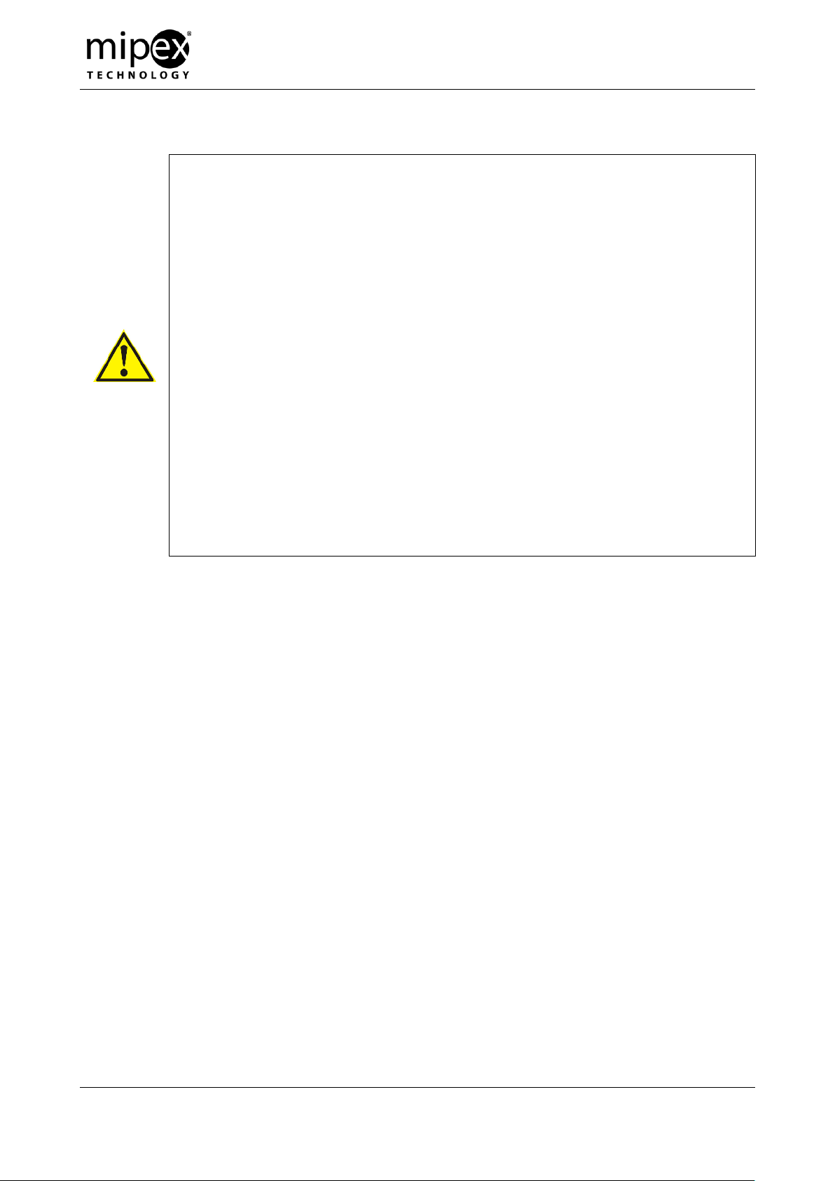
During first 0.1 seconds after power up, sensor consumes up to 25 mA, and
then during one second average current consumption is about 10 mA (see Fig.
1). After that sensor switches to the normal current consumption mode.
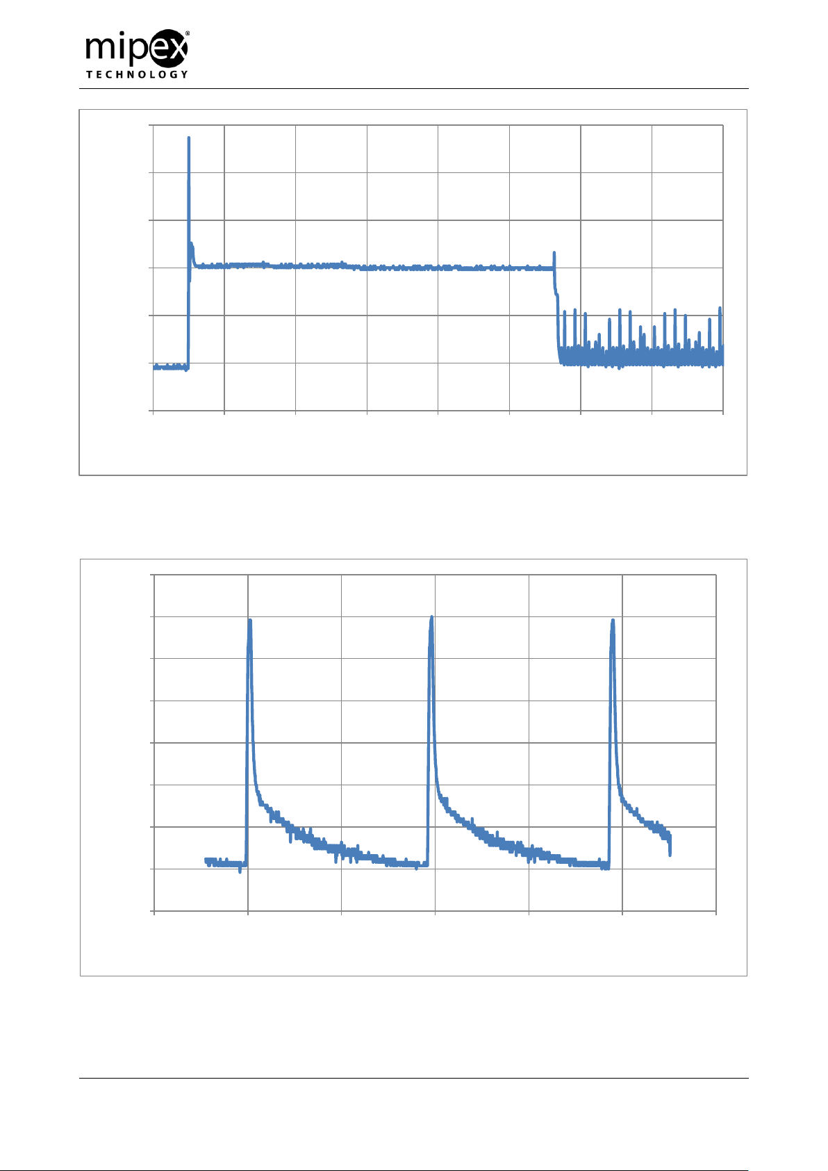
During operation, MIPEX-02 has pulsed current consumption. Pulse repetition
period is 10 ± 20% ms (depends on ambient temperature).
During operation, maximum surge current is 10 mA (see Fig. 2). Average
current consumption is not more than 1 mA (for power consumption of sensor
connected via barrier see Fig. 4 and Fig. 5).
Average current consumption may increase up to 10 mA over about 60 ms
when UART is active. Pulse repetition period is increased by the time of data
processing on UART (see Fig. 3).
6.3. Electrical conditions
Use intrinsically safe circuit connections represented in Appendix B.
Sensor power supply has to follow requirements of IEC 60079-0 and IEC 60079-11, with
rated output range of intrinsically safe DC voltage (U0) of +3.0…+5.0 V, with rated power range
(P0) of 0.02…0.25 W. Current provided by power supply unit must be 25 mA < I0 ≤ 450 mA.
End-user equipment UART transceiver should meet the requirements of standards
IEC 60079-0, IEC 60079-11.
Sensor UART transceiver communication properties are:
High logic level for transmitting line TxD is in range of +2.4…+2.7 V;
High logic level for receiving line RxD is in range of +2.4…+3.4 V;
Low logic level is in range of 0…+0.8 V;
Maximum output current of UART is not more than 25 mA.
Optosense LLC
USER MANUAL
Design department
SMALL-SIZE EXPLOSIVE GAS MEASURING
SENSOR MIPEX-02-X-X-X.1 X (RX)
ESAT.413347.005 UM
Revision 3.0
January 19th, 2017
Page 13 of 46
THE SOLE PROPERTY OF OPTOSENSE LLC. ANY REPRODUCTION WITHOUT THE WRITTEN PERMISSION OF OPTOSENSE LLC IS PROHIBITED.
-0.5
0
0.5
1
1.5
2
2.5
-0.1 0.1 0.3 0.5 0.7 0.9 1.1 1.3 1.5
Voltage, V
Time, s
-0.1
0
0.1
0.2
0.3
0.4
0.5
0.6
0.7
-0.015 -0.01 -0.005 0 0.005 0.01 0.015
Voltage, V
Time, s
Fig. 1. Typical sensor voltage drop after power up (input voltage 3.3 VDC, load resistance
R = 100 Ohm)
Fig. 2. Typical sensor voltage drop (input voltage 3.3 VDC, resistance 100 Ohm)

Optosense LLC
USER MANUAL
Design department
SMALL-SIZE EXPLOSIVE GAS MEASURING
SENSOR MIPEX-02-X-X-X.1 X (RX)
ESAT.413347.005 UM
Revision 3.0
January 19th, 2017
Page 14 of 46
THE SOLE PROPERTY OF OPTOSENSE LLC. ANY REPRODUCTION WITHOUT THE WRITTEN PERMISSION OF OPTOSENSE LLC IS PROHIBITED.
-0.1
0
0.1
0.2
0.3
0.4
0.5
0.6
0.7
0.8
0.9
-0.02 -0.01 0 0.01 0.02 0.03
Voltage, V
Time, s
Fig. 3. Typical sensor voltage drop when UART is active (<@> command)
Fig. 4. Typical barrier voltage drop waveform (3.3 V input)
 Loading...