

MIOX RIO-S Maintance Manual
RIO-S Series On-Site Generator
Installation, Operation, and Maintenance
Manual
MIOX RIO-S™ Operators Manual 102-00130-D Page 1
26 March, 2019
MIOX RIO-S Series Operators Manual
MIOX maintains a constant product improvement program that may affect design and/or
specifications. The company reserves the right to make these changes without prior notice or
liability. Portions of the MIOX OSGs are covered by U.S. Patent
Customer Service
5601 Balloon Fiesta Parkway NE, Suite A
Albuquerque, NM 87113
Phone: 1.505.343.0090
Toll Free: 1.866.MIOX.HLP (1.866.646.9457)
FAX: 1.505.343.0093
Contact@Mioxservice.com
www.MIOX.com
www.DeNora.com
International distributors and sales agents located worldwide
102-00130-D Page 2
MIOX RIO-S Series Operators Manual
CONTENTS
CONTENTS .............................................................................................................. 3
List of Figures ........................................................................................................ 5
List of Tables .......................................................................................................... 5
INTRODUCTION AND OVERVIEW ............................................................................ 6
Regulatory Compliance ............................................................................................. 6
U. S. Environmental Protection Agency (US EPA) .......................................................... 6
List of Certifications .................................................................................................. 6
NSF International ..................................................................................................... 6
State Approvals ....................................................................................................... 6
System Description .................................................................................................. 7
System Space Requirements ..................................................................................... 8
RIO-S Components ................................................................................................ 10
Installation Preparation ....................................................................................... 13
SAFETY PRECAUTIONS AND WARNINGS ..................................... 13
Standard packing list .............................................................................................. 13
Additional Installation Materials ................................................................................ 14
Tools for Installation ............................................................................................... 14
Installation Location Requirements ........................................................................... 14
Receiving and Unpacking the RIO-S OSG ................................................................... 15
INSTALLING the RIO-S ......................................................................................... 16
Securing the Cabinet .............................................................................................. 16
Plumbing Overview ................................................................................................ 16
Electrical Overview ................................................................................................. 19
Water Boost and Brine Boost relays utilize high voltage, ............. 27
proper caution should be used when wiring. ............................................................... 27
Panels are interlocked for your safety. Cells operate at high ........... 29
voltage and store hazardous energy. Do not remove cell guards until 60 seconds after
disconnecting all power sources. .............................................................................. 29
Plumbing/Installing the Brine Tank ........................................................................... 34
Brine Boost System Installation (Optional) ................................................................. 36
Plumbing/Installing the Oxidant Storage Tank ............................................................ 38
OPERATION of the RIO-S ..................................................................................... 44
102-00130-D Page 3

MIOX RIO-S Series Operators Manual
Initial Startup ........................................................................................................ 44
Normal Operation .................................................................................................. 46
Interface elements ................................................................................................. 47
Communications .................................................................................................... 50
Modes of Operation ................................................................................................ 51
Long Term System Shutdown Procedure .............................................................. 53
Troubleshooting ................................................................................................... 54
Fault Conditions ..................................................................................................... 54
Troubleshooting Guide ............................................................................................ 56
Water Flow Control Valve Re-Set Procedure ............................................................... 60
Electrolytic Cell Replacement ................................................................................... 61
Maintenance ......................................................................................................... 62
Daily Maintenance .................................................................................................. 62
Weekly Maintenance ............................................................................................... 63
Monthly Maintenance .............................................................................................. 63
Quarterly Maintenance ............................................................................................ 64
Yearly Maintenance ................................................................................................ 64
Rupture Disk ......................................................................................................... 65
Leak Detection ...................................................................................................... 67
Acid Washing Cell .................................................................................................. 68
Oxidant Demand Testing ......................................................................................... 68
Chlorine Production Testing ..................................................................................... 71
APPENDICES ........................................................................................................ 76
Appendix A - Water Quality Guidelines ...................................................................... 76
Appendix B – Salt Quality Guidelines ........................................................................ 77
102-00130-D Page 4

MIOX RIO-S Series Operators Manual
List of Figures
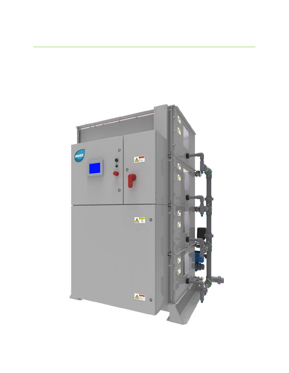
Figure 1: RIO-S On-Site Generator, 4 Cell Bank Configuration ........................................ 7
Figure 2: RIO-S OSG Space Requirements ................................................................... 9
Figure 3: Front External View of RIO-S with Labeled System Components ...................... 12
Figure 4: RIO-S Major Plumbing Components (Non-Electrical) ...................................... 17
Figure 5: External plumbing connections required (3-way valve and Y-strainers not shown)
........................................................................................................................... 18
Figure 6: Electrical cabinet overview ......................................................................... 20
Figure 7: Main Power to RIO-S OSG .......................................................................... 21
Figure 8: Internal view of Controls Cabinet showing major electrical components ............ 22
Figure 9: Internal view of Switchgear Cabinet showing major electronic components ....... 24
Figure 10: Modules 1 & 2 M12 Designations ............................................................... 25
Figure 11: Left View of RIO-S Showing External Connections (Cell Enclosure Hidden) ...... 26
Figure 12: Typical Cell Bank Wiring Diagram: Top View ............................................... 28
Figure 13: External Plumbing Electrical Overview: Rear ............................................... 30
Figure 14: External Plumbing Electrical Overview: Right (Outlet) .................................. 31
Figure 15: Modules 3, 4 & 6 M12 Designations ........................................................... 33
Figure 16: Module 5 M12 Designations ...................................................................... 34
Figure 17: Brine Tank Float Assembly ....................................................................... 35
Figure 18: internal view of the brine tank with/without quartz rock bed ......................... 35
Figure 19: Brine Pressure Boost System .................................................................... 37
Figure 20: Oxidant tank assembly ............................................................................ 38
Figure 21: Oxidant Tank Safety Placard Locations ....................................................... 39
Figure 22: Hydrogen Ventilation Requirements ........................................................... 40
Figure 23: Oxidant Pressure Transducer Assembly ...................................................... 41
Figure 24: Level Switch Installation .......................................................................... 42
Figure 25: HMI Main Screen .................................................................................... 48
Figure 26: HMI Cell Bank Manual Enable/Disable Interface ........................................... 52
Figure 27: Location of Water Control Valve Relative to Inlet/Outlet Plumbing Connections 61
Figure 28: Rupture Disk and Leak Detect Assemblies .................................................. 65
Figure 29: Ruptured Diaphragm ............................................................................... 66
Figure 30 Leak Detect Sensing Band Removal ............................................................ 67
List of Tables
Table 1: Feed Water Requirements ........................................................................... 19
Table 2: Fault Conditions Descriptions ....................................................................... 54
Table 3: Fault Conditions Troubleshooting Guide ......................................................... 56
102-00130-D Page 5

MIOX RIO-S Series Operators Manual
INTRODUCTION AND OVERVIEW
This manual is intended to provide basic installation, operation, and maintenance guidelines
for the operator of the RIO-S on-site generator (OSG). Variations between model types may
cause the images in this manual to not directly reflect the setup of every unit.
Properly operating and maintaining the system will increase cell life and overall system
performance. If you encounter problems or have questions not covered in this manual,
please contact MIOX Service at 1-888-646-9457.
Regulatory Compliance
U. S. Environmental Protection Agency (US EPA)
On-site generated oxidants are listed as a compliance technology for water disinfection. To
be listed as a compliance technology, the system must be cost effective and achieve
compliance with the regulated maximum contaminant levels (MCLs), and the operator must
be capable of reliably operating the technology. The on-site oxidant category was added to
this list in 1997 primarily based on independent research of MIOX technology.
List of Certifications
EPA Registration Number: 69723-NM-001
NSF International
MIOX maintains a policy of verification and compliance of MIOX technology for water
applications. The NSF Standard provides the criteria used to evaluate the public health
safety of materials, components, products, or systems that contact drinking water, drinking
water chemicals, or both. For details of specific NSF standards for specific MIOX equipment,
please consult with MIOX. NSF listings are also available through NSF International at (800)
NSF-MARK or their web site at www.nsf.org.
State Approvals
MIOX maintains a policy of obtaining state regulatory approval in all states where MIOX
equipment is installed and operated. MIOX has never been rejected for approval in any
state. For a complete list of states currently approving on-site oxidant technology, please
contact MIOX.
102-00130-D Page 6
MIOX RIO-S Series Operators Manual
System Description
The MIOX RIO-S system is an on-site disinfectant generator that creates a disinfectant
solution from water, salt, and electricity. The system can create 250-1200 lbs. of Free
Available Chlorine (FAC) per day for the Mixed Oxidant model and 400-2000 lbs. FAC per
day on the Sodium Hypochlorite model, depending on the number of modules installed and
supplied voltage.
Figure 1: RIO-S On-Site Generator, 4 Cell Bank Configuration
102-00130-D Page 7

MIOX RIO-S Series Operators Manual
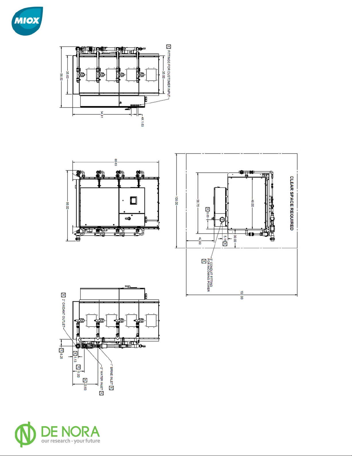
System Space Requirements
Space Requirements
Appropriate floor-space must be identified to accommodate the OSG and sufficient working
space clearance (Figure 1-2). The enclosure is 66 in. (1.68m) wide by 56.5 in. (1.43m)
deep by 80.63 in. (2.04m) tall including the pre-installed external plumbing. Front clearance
from the unit must be a minimum of 42 in. (1.07m), and rear clearance must be a minimum
of 33.5 in. (0.85m). Clearance on both sides of the unit must be at least 30 in. (0.76m)
from the outer face of the enclosure. Refer to Figure 2 for a detailed view of clearance
requirements.
Note: Additional floor space will be required for an oxidant storage tank, brine
generator, water softener, brine pressure boost system, and depending on the
installation, salt storage. Additional floor space will also be required for the
injection system and additional booster pumps.
Security
MIOX equipment must be installed in a building or protected structure that provides shelter
from the weather and extreme temperature variances, and which can be locked or
otherwise secured. Physical security is required to ensure that unauthorized persons cannot
access the unit.
102-00130-D Page 8
MIOX RIO-S Series Operators Manual
Figure 2: RIO-S OSG Space Requirements
102-00130-D Page 9

MIOX RIO-S Series Operators Manual
RIO-S Components
RIO-S OSG System and Ancillary Components
Electrolytic Cell
The proprietary membrane-less electrolytic cell produces a mixture of oxidants and is
manufactured by MIOX. For the MOS version, the RIO-S cell is configured to provide 62-75
lbs/day of Free Available Chlorine (FAC). There are 4 cells per cell bank providing 250-300
lbs/day FAC per cell bank with a maximum of four banks 1000-1200 lbs/day FAC. For the
HYPO version, the RIO S cell provides 100-125 lbs/day FAC corresponding to 400-500
lbs/bank and 1600-2000 lbs/day maximum on 4 bank units.
The electrolytic reaction that takes place within the cell occurs under pressure (5-25 psi, 34172 kPa). The cell is equipped with a rupture disc (pressure relief port) that is designed to
rupture in the event of over-pressurization within the cell.
Main Power Disconnect
This compartment contains the main power connection to the OSG as well as the main
breaker. Refer to the Electrical Overview section for more detailed information.
Switch Gear Cabinet
The Switch Gear Cabinet contains all of the major electrical components that relate to
supplying/monitoring power to the cells. Refer to the Electrical Overview section for more
detailed information.
Controls Cabinet
This cabinet contains all of the electrical components that correspond to the operation of the
OSG as well as the Human-Machine Interface (HMI) display that allows the user to operate
the RIO-S. Refer to the Electrical Overview section for more detailed information.
Water Softener
All MIOX equipment requires soft water. Hard water will cause severe damage to the cell.
Water hardness must be maintained at less than one grain/gallon (17.1 mg/L of
CaCo3). The softener resin is recharged with brine from the brine generator. The correct
sized recharge meter disc is determined by water hardness.
Brine Generator
The capacity of brine generators ranges from 500 lb., manually loaded systems, to 160,000
lb. systems, pneumatically loaded from a transport truck. A mechanical float valve assembly
which monitors the brine level is included with the brine generator.
Oxidant Storage Tank
102-00130-D Page 10

MIOX RIO-S Series Operators Manual
The oxidant storage tank is an integral part of an on-site generator and is sized to meet the
injection demand at the peak hourly flow. The oxidant tank must be vented directly to the
atmosphere outside the facility.
Brine Pressure Boost System
A brine pressure boost system insures that sufficient brine pressure is supplied to the brine
metering pump to maintain optimal cell operation amperage. A separate electrical circuit is
required for the brine boost system.
Plumbing and Fittings
All plumbing and fittings shipped by MIOX meet Schedule 80 specifications. The U.S.
specifications ensure that materials are rated for proper thickness, pressure requirements,
and temperature resistance for the specific application.
RIO-S Series OSG System Optional Equipment
Heater or Chiller
If the OSG feed water temperature is less than 40°F (5°C) or greater than 95°F (35°C),
damage to the electrolytic cell will occur. A water heater or chiller is recommended to bring
the water temperature into range.
Oxidant Solution Injection System
MIOX can supply injection systems to dose raw water with disinfectant. These systems
come with separate installation and operation instructions.
Water Pressure Boost System
A water pressure boost system can be included to insure minimum water pressure for OSG
operation and support of water softener regeneration. A separate electrical circuit is
required for the water pressure
102-00130-D Page 11
MIOX RIO-S Series Operators Manual
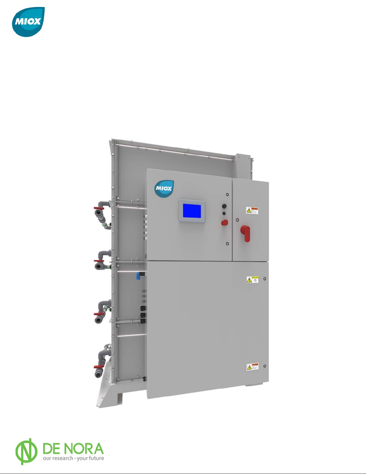
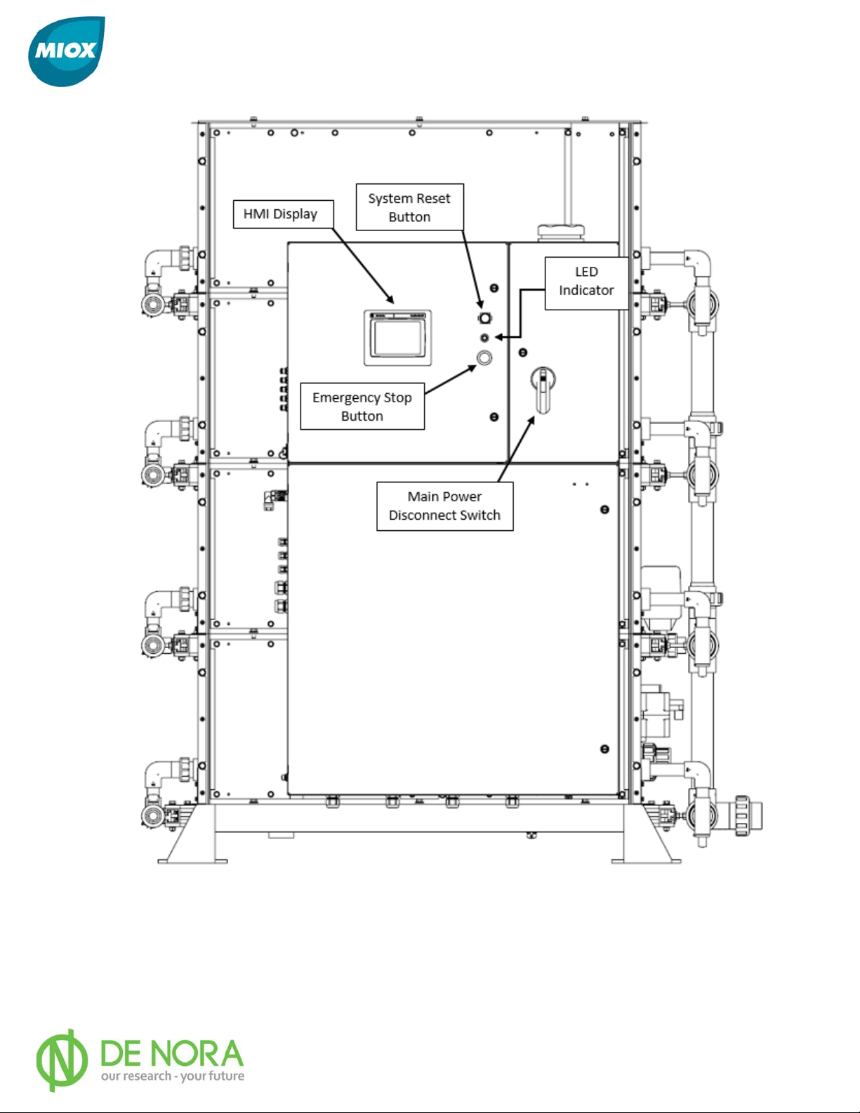
Figure 3: Front External View of RIO-S with Labeled System Components
102-00130-D Page 12

MIOX RIO-S Series Operators Manual
Installation Preparation
Your RIO-S OSG has been factory tested and must be properly installed by technicians
trained by MIOX or its representatives. This chapter describes the procedures for unpacking
and installing the RIO-S OSG and auxiliary equipment, including all requirements for
plumbing and electrical tie-ins. Specifications and conditions regarding electrical power to
the unit, water quality, water line pressure requirements, and other requirements for
installation of your OSG are discussed.
Safety
SAFETY PRECAUTIONS AND WARNINGS
Ensure that the facility and the installation are in conformance with all codes
and standards.
Please refer to the MIOX Hydrogen Safety White Paper or your local authority
having jurisdiction for more information. Untrained persons should not
attempt to install or operate MIOX OSGs.
A liquid barrier system is mandatory. Ensure that all hydrogen vent lines
slope towards the oxidant tank.
Ensure that no valves, drop legs, or P-traps are in the hydrogen vent lines.
Do NOT cross connect vent lines.
Ensure that brine and oxidant tanks are labeled properly.
Disconnect power before working on the system. Do not reconnect the power
to switch gear enclosure until installation is complete.
All MIOX systems require a good earth ground. A neutral is not a substitute
for a proper earth ground. Electrical wiring to all MIOX systems should be
performed by a certified electrician. The circuit feeding the MIOX OSG should
be separated from other power devices.
Failure to install unit properly can result in electrical shock.
Standard packing list
1. RIO-S OSG
2. RIO-S Installation, Operation, and Maintenance Manual
3. Documentation Kit
4. Brine Tank (if ordered)
5. Oxidant Storage Tank with Hydrogen Vent Kit (if ordered)
6. 2” 3-way oxidant sampling valve
7. 2” Oxidant Check Valve
102-00130-D Page 13

MIOX RIO-S Series Operators Manual
Additional Installation Materials
1) 400-480 VAC circuit with designated ground.
Note: amperage ratings vary based on the number of cell banks:
a. 250-500 Lbs/day (1 bank) – 100A
b. 500-1000 Lbs/day (2 bank) – 200A
c. 750-1500 Lbs/day (3 bank) – 300A
d. 1000-2000 Lbs/day (4 bank) – 400A
2) Saturated Brine Supply (see MIOX Salt Quality Guidelines for salt
specifications)
3) Fresh Water Supply (see Appendices for Water Quality Guidelines)
4) Oxidant Storage Tank with Hydrogen Venting (see Hydrogen Safety White
Paper for details)
5) Pressure Transducer or Level Switch Assembly (provided with OSG)
6) Input Power Connection (not included)
7) Concrete Anchor Bolts
Tools for Installation
Mechanical Tools
• Forklift, pallet jack, or crane - unload and place equipment
• Hammer - remove crating
• Pry bar - remove crating
• 2-¾” end wrenches or equivalent - connect cell
• Channel locks or equivalent slip joint pliers - tighten plumbing connections
• Phillips screw driver - make main electrical connections
• Small flat screwdriver - connect control relay wiring
• Wire strippers
• Allen wrench set
• Tape measure
Plumbing Tools
• PVC pipe cutter or saw
• PVC pipe reamer - remove burrs from cut pipe
• Glue - use correct type for pipe material
• Primer/cleaner - use correct type for pipe material
• Teflon Tape
• Strap wrench
• 12” pipe wrench
Installation Location Requirements
The RIO-S OSG must be installed indoors on a flat level surface approximately 66 in by 56.5
in (1.68 m by 1.44 m) not including the space for clearance described in the System Space
Requirements section of this manual. The ambient air temperature at the installation
location must be between 40°F (5°C) and 110°F (43°C). Additional space will be required
for the water, brine, and oxidant tanks. MIOX recommends placing the OSG and tank near
102-00130-D Page 14

MIOX RIO-S Series Operators Manual
an available drain for ease of draining the tank or in case of minor overflows. Additionally,
MIOX recommends placing the oxidant tank near an external wall for ease of hydrogen
venting as described in the Hydrogen Safety White Paper.
NOTE: Failure of the system that can be traced to improper
temperature conditions is not covered under the MIOX warranty.
Receiving and Unpacking the RIO-S OSG
Your RIO-S OSG has been carefully packed to avoid shipping and handling damage.
The OSG is shipped on a crated pallet. Brine generator tanks, oxidant tanks, water
softeners, and other ancillary equipment are shipped on separate pallets. To safely
unpack the OSG complete the following steps:
1. Unpack the OSG - Remove the crate from around the enclosure. Check the
enclosure for any damage that may have occurred during shipping.
2. Unpack Installation Kits - Remove the contents from the brine generator and
oxidant storage tanks. These items include the OSG installation kit, the tank level
switch(s), the softener installation kit, and the solution tank drop tube.
3. Unpack the water softener - Remove the water softener towers from their
packaging. Do not turn the softeners over or lay them on their sides as this will
disturb the softening resin and gravel beds inside the softener and affect softener
performance.
4. Unpack all other equipment - Remove any optional components (heaters,
chillers, injection systems, etc.) from their packaging and inspect for damage. After
completing a visual inspection, compare ordered items against what was delivered.
Should you find anything damaged or missing, please contact your MIOX sales agent
or MIOX Customer Service.
102-00130-D Page 15

MIOX RIO-S Series Operators Manual
INSTALLING the RIO-S
Untrained persons should not attempt to
install or operate MIOX equipment.
Securing the Cabinet
The RIO-S OSG is designed with mounting feet and holes for securing the unit to the
floor. While there are no vibrational components that would cause the system to
move, good seismic design practice as well as building codes in some areas require
that the unit be secured to the floor. Concrete anchors or other suitable hardware is
recommended to secure the RIO-S OSG to the floor. Consult local seismic codes for
site-specific requirements.
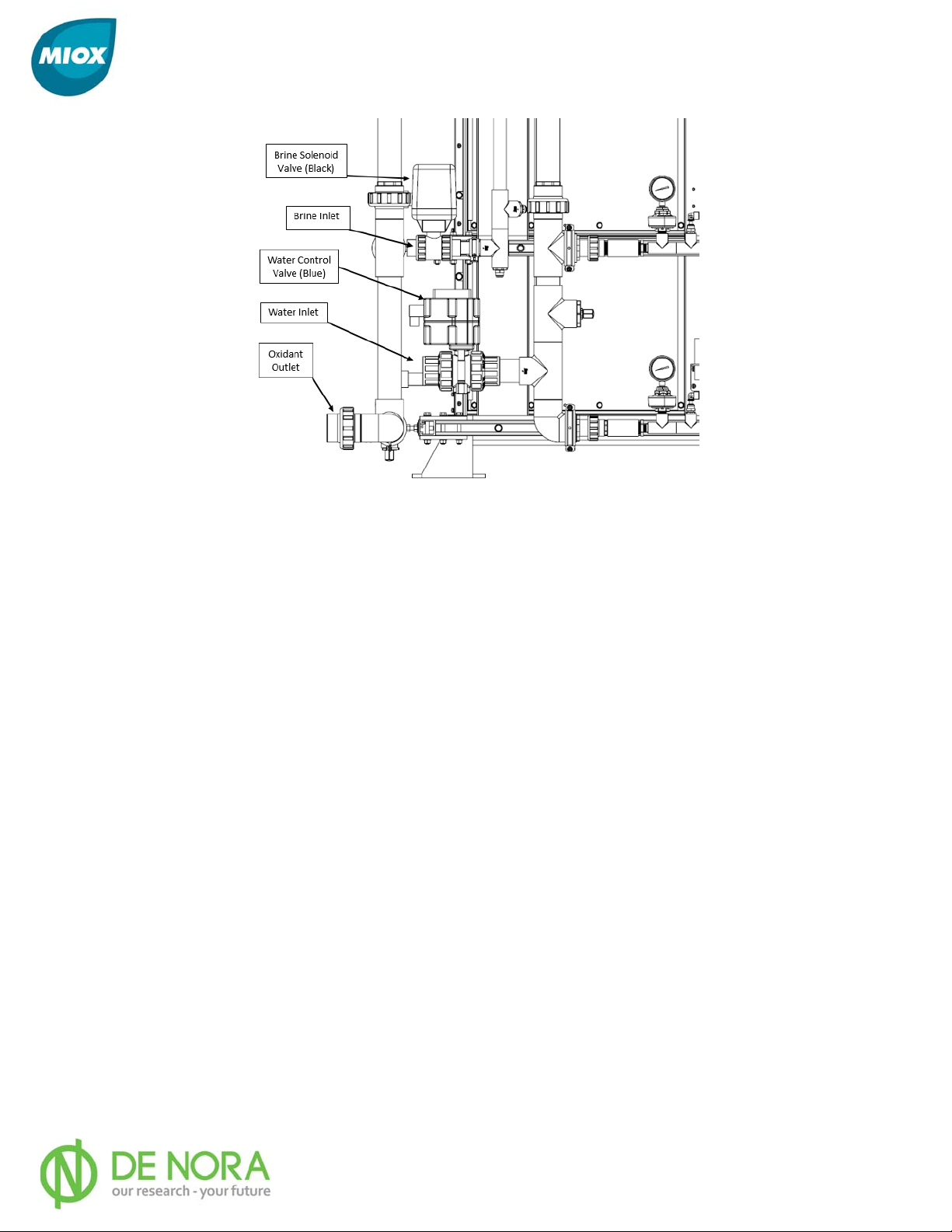
Plumbing Overview
The RIO-S OSG comes with all system plumbing pre-installed at the factory. The only
connections made by the customer to the generator itself are the water input line, brine
input line, and the oxidant outlet line. The brine and water connections are made via PVC
union connectors (1” for brine, 2” for water) to the large Y-strainers located behind the cell
enclosure close to the ground. The oxidant outlet connects to the third pipe located near the
Y-strainers via a 2” CPVC union. If needed, refer to Figures 4 and 5 for the locations of all
major plumbing components, and below for a summary of the more operator-relevant
components. If additional clarification is needed, contact your MIOX Customer Support
provider.
102-00130-D Page 16
MIOX RIO-S Series Operators Manual
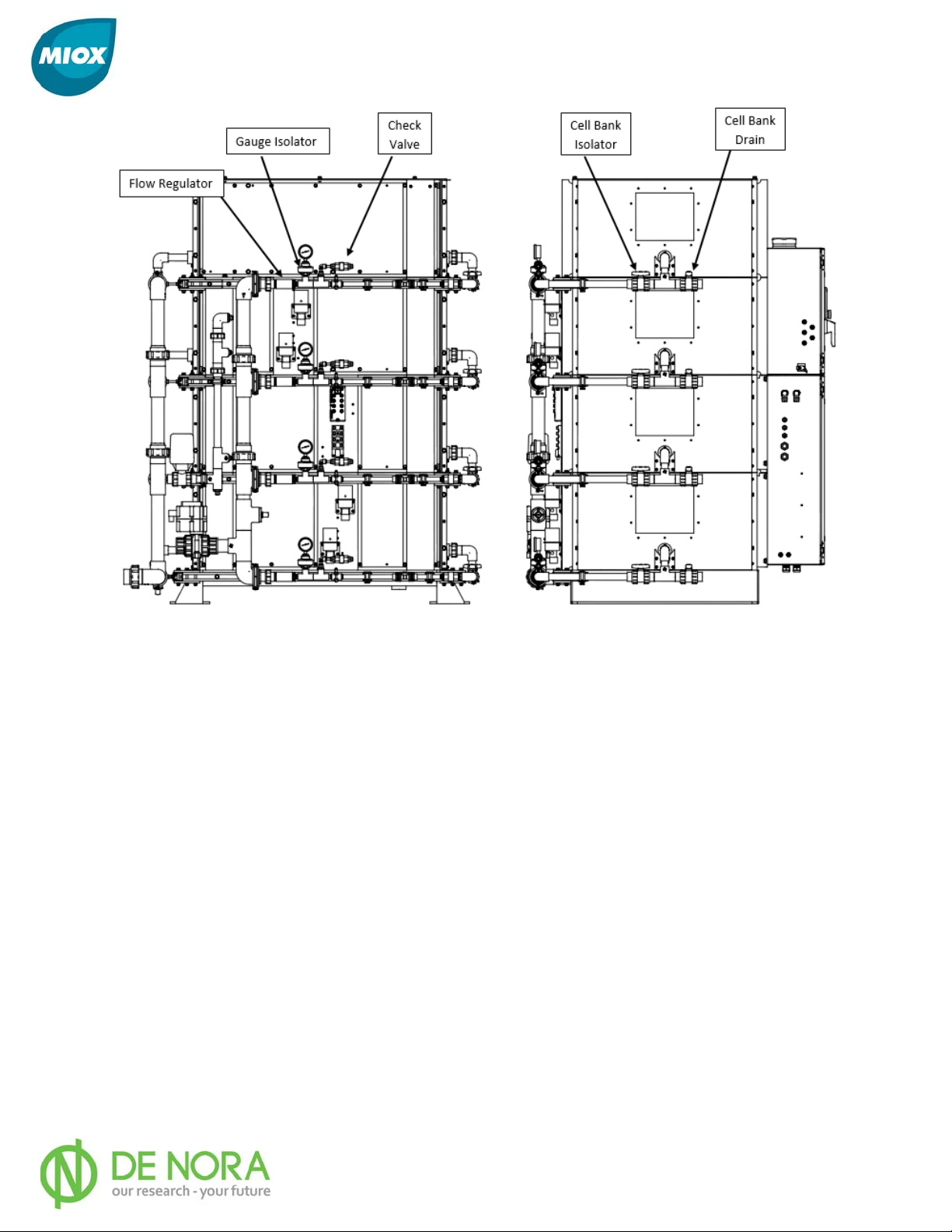
Figure 4: RIO-S Major Plumbing Components (Non-Electrical)
Cell Bank Isolator Valve
o These ball valves (1 per bank, max 4) can be used to isolate the banks from
one another for maintenance and troubleshooting purposes.
Cell Bank Drain Valve
o These ball valves (2 per bank, max 4) can be used to drain the banks of their
contents for maintenance and troubleshooting purposes. There are drain
valves located on both sides (water inlet and oxidant outlet) of each bank to
facilitate draining and acid wash connections.
Inlet/Outlet Plumbing Requirements
All water and brine systems are compatible with schedule 80 PVC. MIOX strongly
recommends schedule 80 CPVC for all mixed-oxidant or sodium hypochlorite solution
connections and hydrogen venting. Where possible, all connections should be solvent
welded rather than threaded to prevent the possibility of leaks. All piping should be
supported at 3 - 4 ft. (1 m) intervals. Isolation valves should be included on all inlet lines
external to the RIO-S OSG. Refer to figure 5 for a picture of all external connections
necessary for operation of the RIO-S.
102-00130-D Page 17
MIOX RIO-S Series Operators Manual
Figure 5: External plumbing connections required (3-way valve and Y-strainers not shown)
Sampling Valve Installation
MIOX supplies a three-way valve to allow for sampling of the disinfectant solution to verify
system performance. MIOX also supplies a check valve and strongly recommends installing
the valve on the oxidant discharge line. The valve should be installed immediately after the
three-way valve sample port to prevent the backflow of oxidant/hypochlorite into the
electrolytic cell.
Feed Water Requirements
Feed water requirements for the RIO-S OSG are given in Table 1. Additional feed water
flow rate is based on water softener requirements. Consult water softener specifications for
required flow rates. A minimum feed water pressure at the OSG of 50 PSI (345 kPa) for
systems with 1-3 banks and 60 PSI (414 kPA) for 4 bank systems; is required to ensure
stable flow and a continuous supply of 5-25 PSI (34-172 kPa) brine feed to the electrolytic
cell. To protect against low water pressure, an auto adjusting flow control valve is included
in the piping manifold to compensate for inconsistent flow and pressure fluctuations. It uses
a turbine flow sensor that sends pulses to the PLC when the turbine is spinning. Based on
the rate of the pulses, the system can calculate the feed water flow rate and adjust the flow
control valve accordingly. This setting is critical for proper oxidant production, cell cooling,
and other key operating parameters. A liquid filled pressure gauge is included in the
plumbing assembly to visually monitor the cell pressure (Figure 4). Maximum supply
pressure to the RIO-S OSG should not exceed 100 PSI (689 kPa). For supply pressure above
100 PSI (689 kPa), a pressure regulator must be added to lower the pressure to the before
mentioned specified range.
102-00130-D Page 18
MIOX RIO-S Series Operators Manual
Table 1: Feed Water Requirements
1-Bank 2-Bank 3-Bank 4-Bank
480V Flow GPH (LPH) 380 (1438) 760 (2877) 1140 (4315) 1520 (5754)
400V Flow GPH (LPH) 304 (1150) 608 (2300) 912 (3450) 1216 (4600)
Electrical Overview
Safety
The RIO-S operates at high voltage in close vicinity to water. As such, normal
precautions should be taken with regard to electrical components in the vicinity of a
water source.
DO NOT APPLY POWER TO THE UNIT UNTIL INSTALLATION IS 100% COMPLETE.
Front Main Electrical Cabinets:
The majority of the major electrical components (not including the electrolytic cells) for the
RIO-S are located within the three cabinets located on the front of the OSG. These cabinets
are shown in Figure 6, and each come equipped with safety interlocks as well as a clear,
non-conductive barrier behind the main power and switchgear cabinet doors to further
protect the user from coming into contact with charged electrical components. Refer to
each sub-section below for a more detailed description of each cabinet.
102-00130-D Page 19
MIOX RIO-S Series Operators Manual
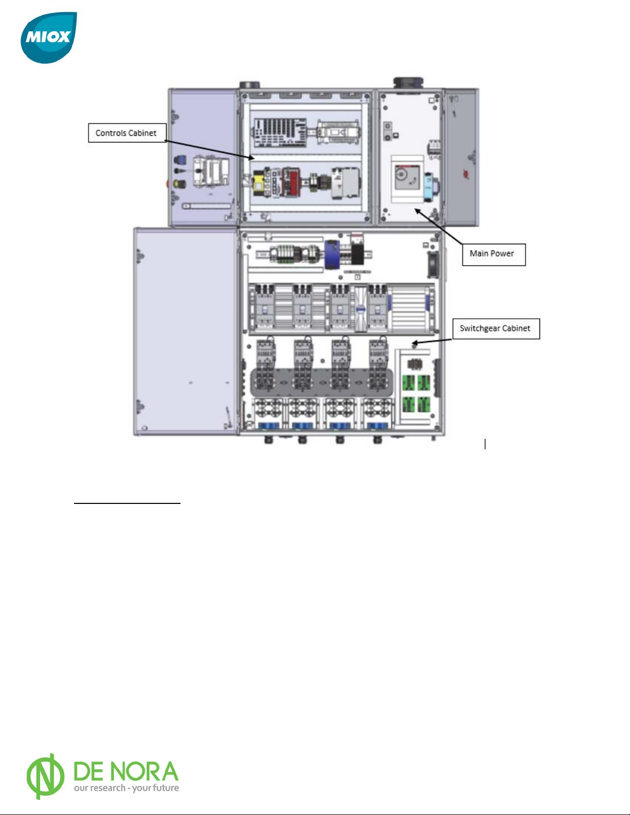
Figure 6: Electrical cabinet overview
Main Power Cabinet:
The main power cabinet holds the main breaker for the OSG. This is where power is routed
into the OSG for distribution. The breaker’s amperage rating varies based on the number of
cell banks installed with one, two, three, and four bank units being equipped with 100A,
200A, 300A, and 400A breakers respectively. The breaker is interlocked with the large red
disconnect switch located on the front of the cabinet and must be turned to the off position
for the door to be able to open.
102-00130-D Page 20
MIOX RIO-S Series Operators Manual
Safety
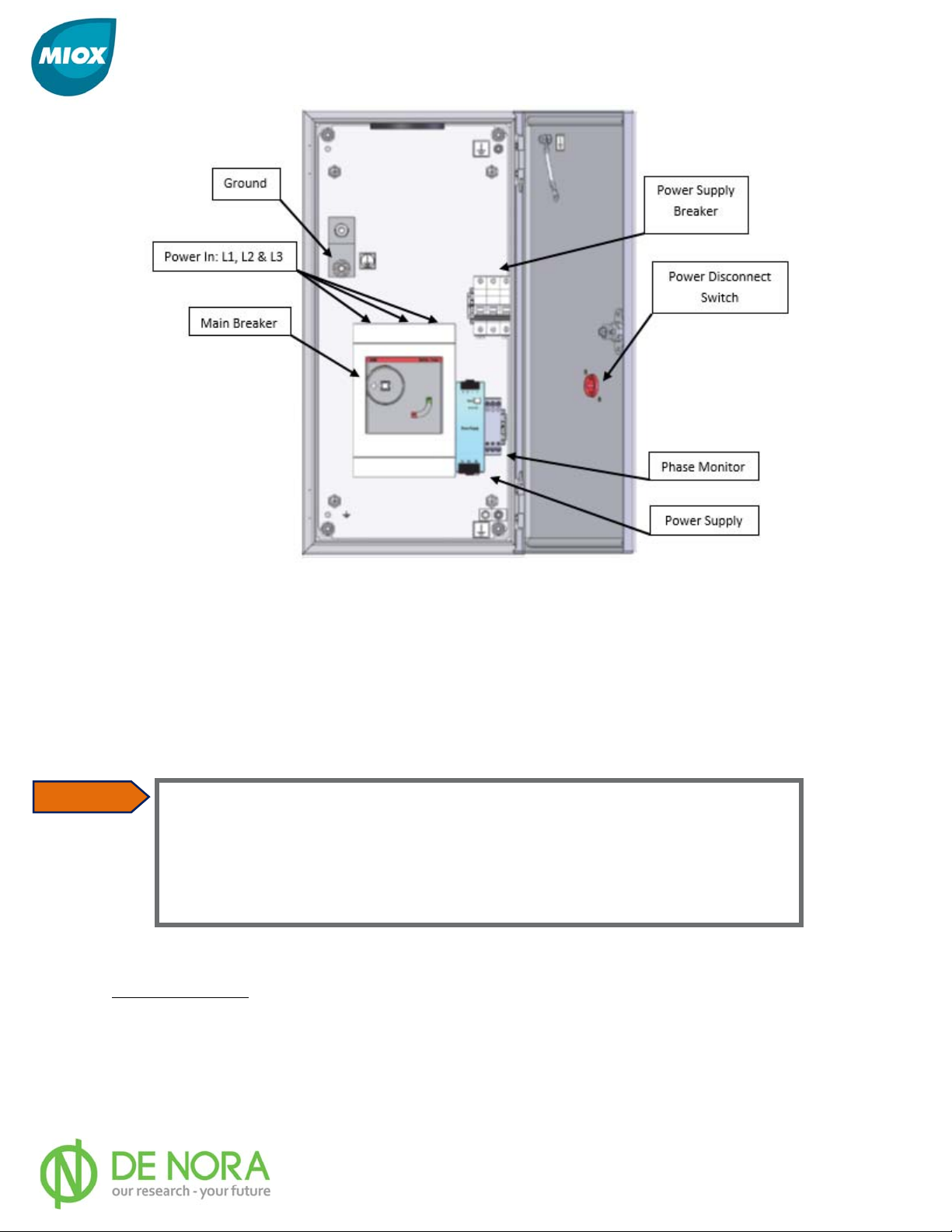
Figure 7: Main Power to RIO-S OSG
Electrical Power Connection
The power cables to the RIO-S are run through the top of the power cabinet via a large
circular conduit. Route the power cable to the conduit then open the front of the cabinet to
screw in the electrical connections to the top of the breaker and the ground to the buss-bar.
Refer to Figure 7 for additional details.
NOTE: Failure of the system that can be traced to a poor power source is not
covered under the MIOX warranty.
All MIOX systems require a good earth ground. A neutral is not a substitute for an earth
ground. Electrical wiring to all MIOX units should be wired on a separate circuit from
other power devices (pumps, etc.). MIOX cannot be held responsible for systems wired
improperly that do not meet UL or National Electrical Code (NEC) requirements. If the
system is improperly grounded, the MIOX warranty is void. If a local code requires a
GFI (Ground Fault Interrupter) circuit breaker, it is the responsibility of the customer to
install the GFI to meet local code requirements.
Controls Cabinet:
The controls cabinet contains the components of the OSG that handle the operating of the
system and comes completely wired internally from the factory. If needed, refer to Figure 8
for the locations of all major electrical components, and below for a summary of the more
operator-relevant components. If additional clarification is needed, contact your MIOX
Customer Support provider.
102-00130-D Page 21
MIOX RIO-S Series Operators Manual
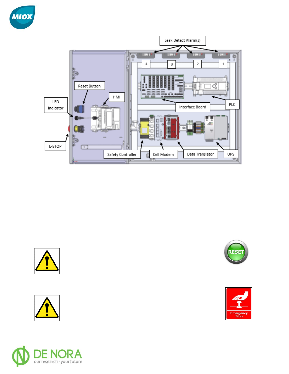
Figure 8: Internal view of Controls Cabinet showing major electrical components
Programmable Logic Controller (PLC)
o The Programmable Logic Controller acts as the controlling unit of the OSG,
this monitors and controls all functions of the OSG.
HMI (Human Machine Interface) Display
o Located on the external door to the cabinet, this acts as the user interface of
the OSG, refer to the Interface Elements section of Operations for more
information. (See Figure 3: Front External View of RIO-S with Labeled System
Components)
Manual Reset Button
o In the event where the system has to be restarted due to an
irregular shutdown (use of the E-Stop, Interlock Switches or
power failure). This button must be pressed to restart the
system (See page 49).
Emergency Stop (E-Stop) Button
o In any event where the system must be shut down immediately
without going through the normal shutdown procedures
programmed into the PLC, this button may be used to do so.
The same shut-down sequence occurs when the Switchgear
door interlock is tripped. The system will then have to be reset
using the Manual Reset button to resume normal operation (see page 48).
102-00130-D Page 22

MIOX RIO-S Series Operators Manual
Data Translator
o Allows data mapping between the PLC, and the various sensors connected to
the RIO-S as well as between these sensors and any SCADA system that the
unit is connected to.
LED indicator
o Located on the external door to the cabinet, displays different colors and light
patterns to indicate the status of the OSG. Refer to the Interface Elements
section of this manual for more information.
Cellular Modem (if equipped)
o If your RIO-S came equipped with remote monitoring, this Modem is the
hardware that supports that functionality. Refer to the Communications
section of this manual for more information.
Safety Controller
o Control System that monitors the various input devices (E-STOP, Leak Detect,
Door Interlocks, etc.) that correspond with the safe operation of the unit.
Uninterruptible Power System (UPS)
o In the event where power to the OSG is lost, the UPS provides ample power
to allow the electronically controlled valves to turn off to prevent overflow.
Additionally, the UPS allows the system to send communications data to a
SCADA system or other monitoring system in the event of a power loss.
Switchgear Cabinet
The RIO-S switchgear cabinet comes completely wired from the factory. If needed, refer to
Figure 9 for the locations of all major electrical components, and below for a summary of
the more operator-relevant components. If there is an event where additional clarification is
needed, please contact your MIOX Customer Support provider.
102-00130-D Page 23
MIOX RIO-S Series Operators Manual
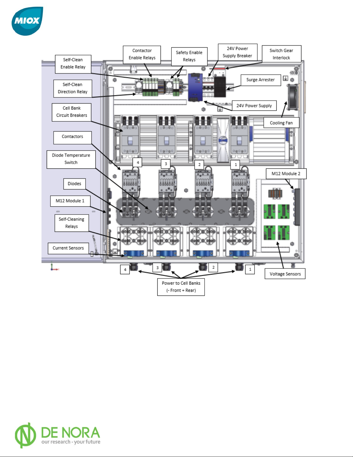
Figure 9: Internal view of Switchgear Cabinet showing major electronic components
Cell Bank Circuit Breakers
o One per cell, individual resettable 80A circuit breakers for each cell bank in
the system (max 4).
Diode Temperature Switch - Thermostats
o One to three thermostats per unit, depending on capacity - located between
diodes. Auto-reset and alarm when junction temperature at heatsink reaches
maximum set point.
Alarm Relay
o Relay that is tripped whenever the system encounters a fault. Can be used to
send signal to various forms of alarm systems (audible, plant status, etc.)
depending on the user’s preference.
Power Monitor
102-00130-D Page 24
 Loading...