

Page 1
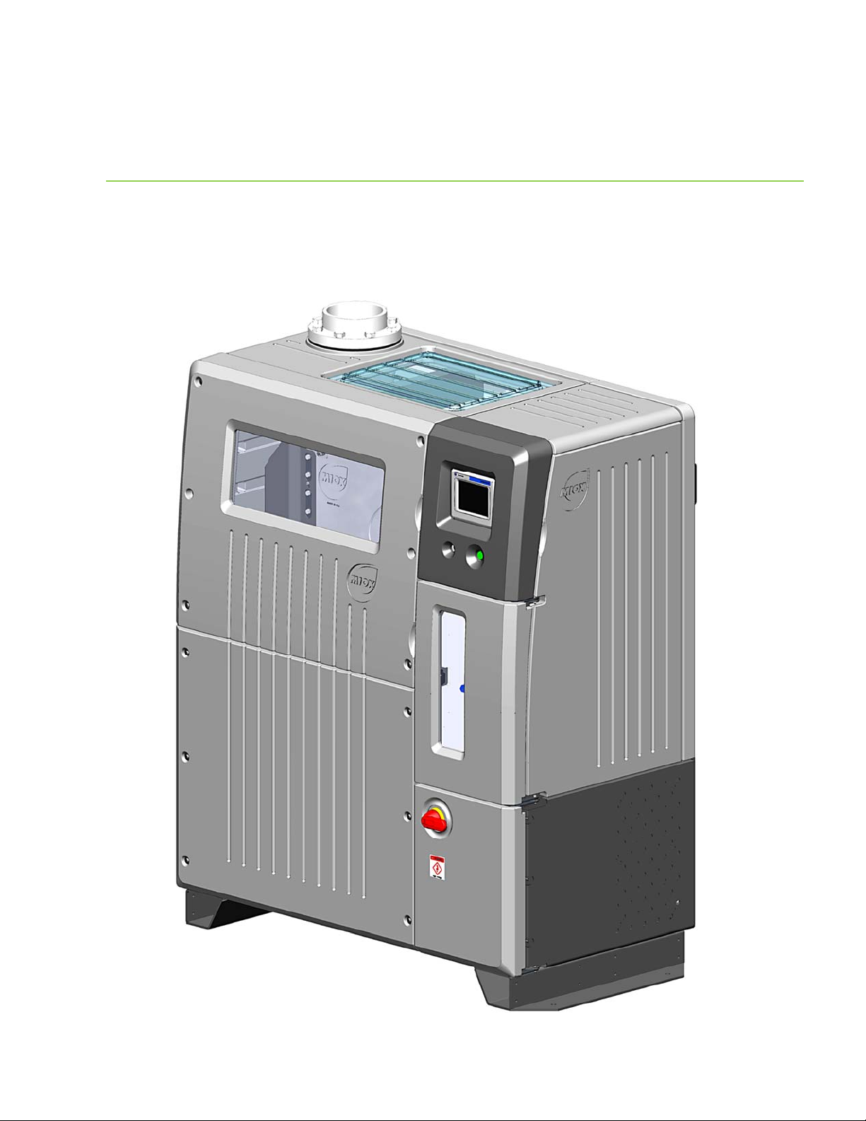
RIO SERIES ON-SITE GENERATOR
M1-M5 H1-H5
Installation, Operation, and Maintenance
Manual
March 26, 2019
Page 2
MIOX RIO Series Operators Manual
MIOX maintains a constant product improvement program that may affect design
and/or specifications. The company reserves the right to make these changes without prior notice
or liability. Portions of the MIOX OSGs are covered by U.S. patent.
Customer Service
5601 Balloon Fiesta Parkway NE, Suite A
Albuquerque, NM 87113
Phone: 1.505.343.0090
Toll Free: 1.866.MIOX.HLP (1.866.646.9457)
FAX: 1.505.343.0093
www.MIOX.com
http://www.denora.com/
International distributors and sales agents located worldwide
P/N: 102-00076-G Page 1
Page 3

MIOX RIO Series Operators Manual
Table of Contents
Introduction ................................................................................................................... 7
Regulatory Compliance ................................................................................................. 7
U. S. Environmental Protection Agency (US EPA) ........................................................... 7
NSF International ..................................................................................................... 7
State Approvals ........................................................................................................ 7
List of Certifications .................................................................................................. 7
Components of the System ........................................................................................... 8
Space Requirements ................................................................................................. 8
Security ................................................................................................................ 10
RIO Series OSG System and Ancillary Components ...................................................... 10
RIO Series OSG System Optional Equipment ............................................................... 11
Installation .................................................................................................................. 12
Recommended Tools for Installation: RIO Series OSG ..................................................... 13
Mechanical Tools .................................................................................................... 13
Plumbing Tools ....................................................................................................... 13
Receiving and Unpacking the RIO Series OSG ................................................................ 14
Securing the Cabinet ............................................................................................... 14
System Description .................................................................................................... 15
Electric Connections Required for Start-Up .................................................................... 16
Electrical Power Connection ...................................................................................... 16
Control System/Rear Panel Connections ..................................................................... 18
Tank Level Inputs ................................................................................................... 19
Auxiliary Relay Connection ....................................................................................... 20
Auxiliary 24V Power Connection ................................................................................ 21
Dilution Air Connection ............................................................................................ 22
Hydrogen/Hardness Connections ............................................................................... 23
Ethernet Connection ................................................................................................ 24
Plumbing Connections Required for Startup ................................................................... 25
Feed Water Connection ............................................................................................ 25
Brine Feed Connection ............................................................................................. 26
Oxidant Discharge .................................................................................................. 27
Drains ................................................................................................................... 28
Brine Generator Installation (Optional) ......................................................................... 29
P/N: 102-00076-G Page 2
Page 4

MIOX RIO Series Operators Manual
Brine Silos ............................................................................................................. 31
Brine Pressure Boost System Installation (Optional) ........................................................ 32
Oxidant Storage Tank Installation ................................................................................ 32
Ventilation Requirements ......................................................................................... 32
Level Switch Installation .......................................................................................... 36
Pressure Transducer Installation (Optional) ................................................................ 37
Oxidant Tank Lid .................................................................................................... 38
Feed Line Connection/Injection System ...................................................................... 38
Overflow Port ......................................................................................................... 38
Cell Installation and Removal ...................................................................................... 39
Removal ................................................................................................................ 39
Installation ............................................................................................................ 39
Electrical Connections .............................................................................................. 40
Plumbing Connections ............................................................................................. 42
Cell Guard Installation ............................................................................................. 44
Operations ................................................................................................................... 46
Initial Settings and Startup Checks ............................................................................... 46
Electrical Check ...................................................................................................... 46
Initial Salt Filling .................................................................................................... 46
Checks Prior to Startup ............................................................................................ 47
Brine Boost Operation ............................................................................................. 47
Water Softener Operation ........................................................................................ 47
Routine Operations .................................................................................................... 48
Turn On Disconnect Switch ...................................................................................... 48
Push Run/Stop Switch ............................................................................................. 48
Startup Sequence/Operating Window ......................................................................... 49
Brine Boost Pump Commissioning ............................................................................. 50
Operation Controls ..................................................................................................... 50
Modes of Operation ................................................................................................. 50
System Status Lights .............................................................................................. 52
Fault Conditions ..................................................................................................... 53
Water Flow Control Valve Reset Procedure.................................................................. 55
System Shutdown procedure ....................................................................................... 55
General Periodic Maintenance ......................................................................................... 56
Daily Maintenance...................................................................................................... 56
P/N: 102-00076-G Page 3
Page 5

MIOX RIO Series Operators Manual
Weekly Maintenance .................................................................................................. 57
Monthly Maintenance.................................................................................................. 58
Quarterly Maintenance ............................................................................................... 58
Annual Maintenance ................................................................................................... 58
Electrolytic Cell Replacement ....................................................................................... 59
Storage of Equipment ................................................................................................. 60
Troubleshooting Guide ................................................................................................... 61
Procedures .................................................................................................................. 67
Brine Pump Replacement ............................................................................................ 67
Removing The Old Brine Pump .................................................................................. 67
Installing the New Brine Pump .................................................................................. 68
Rupture Disk Maintenance ........................................................................................... 68
Replacing the Rupture Disk Diaphragm ...................................................................... 68
Rupture Probe Maintenance ...................................................................................... 69
Acid Washing the Cell ................................................................................................. 69
Oxidant Demand Testing ............................................................................................. 70
Chlorine Production Testing ......................................................................................... 74
APPENDICES ................................................................................................................ 78
Appendix A - Water Quality Guidelines .......................................................................... 79
Appendix B – Salt Quality Guidelines ............................................................................ 81
P/N: 102-00076-G Page 4
Page 6

MIOX RIO Series Operators Manual
ListofFigures
Figure 1 RIO Series On-Site Generator ............................................................................... 8
Figure 2 RIO Series OSG Space Requirements .................................................................... 9
Figure 3 RIO Series OSG Compartments .......................................................................... 15
Figure 4 Rear View of RIO OSG Showing Main Power Conduit .............................................. 16
Figure 5 Incoming Power ............................................................................................... 17
Figure 6 Switch Gear Cover ............................................................................................ 17
Figure 7 Power Routing to Switch Gear ............................................................................ 17
Figure 8 Rear Panel Connections ..................................................................................... 18
Figure 9 Tank Level Connector ........................................................................................ 19
Figure 10 Auxiliary Relay Connector ................................................................................ 20
Figure 11 Auxiliary 24V Power Connector ......................................................................... 21
Figure 12 Dilution Air Connector ..................................................................................... 22
Figure 13 H2/Hardness Connector .................................................................................... 23
Figure 14 Plumbing Enclosure ......................................................................................... 26
Figure 15 Feed Water, Brine, Y-strainer, and Oxidant Union Connections .............................. 27
Figure 16 Float Valve Assembly and Detail ........................................................................ 29
Figure 17 Internal View Float Valve Assembly and Detail .................................................... 30
Figure 18 Brine Pressure Boost System ............................................................................ 32
Figure 19 Oxidant Tank Vents ......................................................................................... 33
Figure 20 Oxidant Storage Tank with Safety Placards ......................................................... 34
Figure 21 Ventilation Requirements ................................................................................. 35
Figure 22 Level Switch Installation .................................................................................. 36
Figure 23 Pressure Transducer Assembly .......................................................................... 37
Figure 24 Cell Lead Connections...................................................................................... 40
Figure 25 Cell Lead and Buss Bar Connection .................................................................... 41
Figure 26 Cell Plumbing Connectons - 1 Module ................................................................ 42
Figure 27 Multiple Module Cell Inlet/Outlet Manifold ........................................................... 43
Figure 28 Cell Guard Pre-Assembly .................................................................................. 44
Figure 29 Location of Socket Head Shoulder Screws – Back ................................................ 45
Figure 30 Location of Socket Head Shoulder Screws - Front ................................................ 45
Figure 31 Display Screen, Run/Stop Switch, and Disconnect Switch ..................................... 48
Figure 32 Main Display Screen ........................................................................................ 49
Figure 33 Switch Gear Panel Components ......................................................................... 65
Figure 34 Interface Board .............................................................................................. 66
Figure 35 Rupture Disk Ruptured Diaphragm .................................................................... 69
Figure 36 Rupture Probe ................................................................................................ 69
P/N: 102-00076-G Page 5
Page 7

MIOX RIO Series Operators Manual
ListofTables
Table 1 Tank Level Connector Name and Description.......................................................... 19
Table 2 Tank Level Status .............................................................................................. 19
Table 3 Auxiliary Relay Connector Name and Description .................................................... 20
Table 4 Auxiliary 24V Power Connector Name and Description ............................................. 21
Table 5 Dilution Air Connector Name and Description ......................................................... 22
Table 6 Hydrogen/Hardness Connector Name and Description ............................................. 23
Table 7 Ethernet Connector Pin-Out ................................................................................. 24
Table 8 Feed Water Requirements ................................................................................... 25
Table 9 Electrical Connections Per Cell Module .................................................................. 40
Table 10 LED Status Lights............................................................................................. 52
Table 11 Output Testing ................................................................................................ 52
Table 12 Fault Conditions ............................................................................................... 53
Table 13 Perimeter Bolt Torque Specifications ................................................................... 57
Table 14 Switch Gear Panel Components .......................................................................... 65
P/N: 102-00076-G Page 6
Page 8

MIOX RIO Series Operators Manual
Introduction
This manual is designed to provide installation, operation, and maintenance guidelines to
the water plant operator. Proper maintenance of the system will increase cell life and
system performance. Follow all warnings and precautions when installing, operating, and
maintaining your On-Site Generator (OSG). Should advanced troubleshooting be required
to solve a problem, please contact your MIOX Customer Service provider for further
assistance.
Regulatory Compliance
U. S. Environmental Protection Agency (US EPA)
On-site oxidants are listed as a compliance technology for water disinfection. To be listed
as a compliance technology, the system must be cost effective and achieve compliance with
the regulated maximum contaminant levels (MCLs), and the operator must be capable of
reliably operating the technology. The on-site oxidant category was added to this list in
1997 primarily based on independent research of MIOX technology.
NSF International
MIOX maintains a policy of verification and compliance of MIOX technology for water
applications. The NSF Standard provides the criteria used to evaluate the public health
safety of materials, components, products, or systems that contact drinking water, drinking
water chemicals, or both. For details of specific NSF standards for specific MIOX equipment,
please consult with MIOX. NSF listings are also available through NSF International at (800)
NSF-Mark or their web site at www.nsf.org.
State Approvals
MIOX maintains a policy of obtaining state regulatory approval in all states where MIOX
equipment is installed and operated. MIOX has never been rejected for approval in any
state. For a complete of states currently approving on-site oxidant technology, please
contact MIOX
List of Certifications
EPA Registration Number: 69723-NM-001
P/N: 102-00076-G Page 7
Page 9
MIOX RIO Series Operators Manual
Components of the System
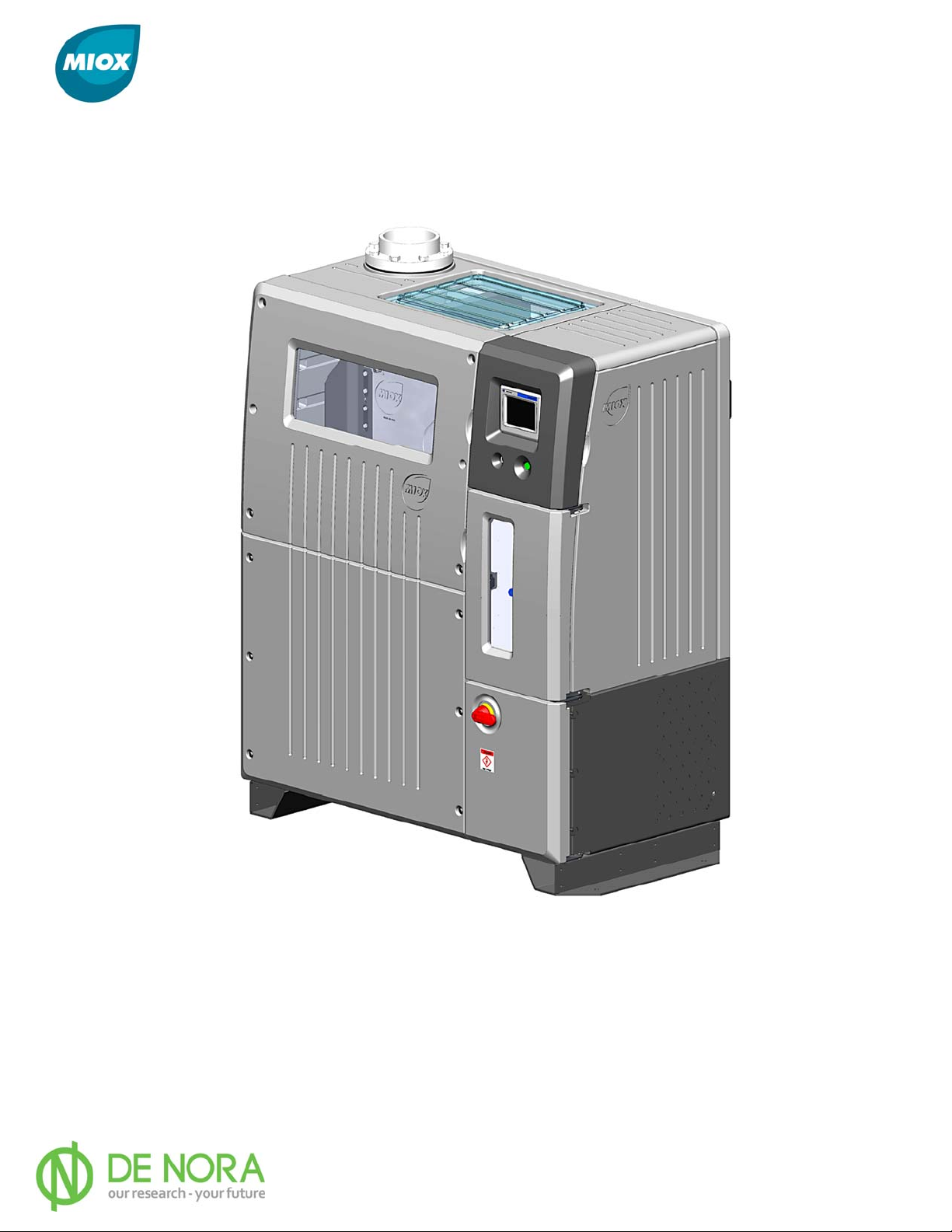
The RIO Series OSG (Figure 1) must be installed by trained technicians. After installation
and system startup, the units operate automatically and self-diagnose.
Figure 1 RIO Series On-Site Generator
Space Requirements
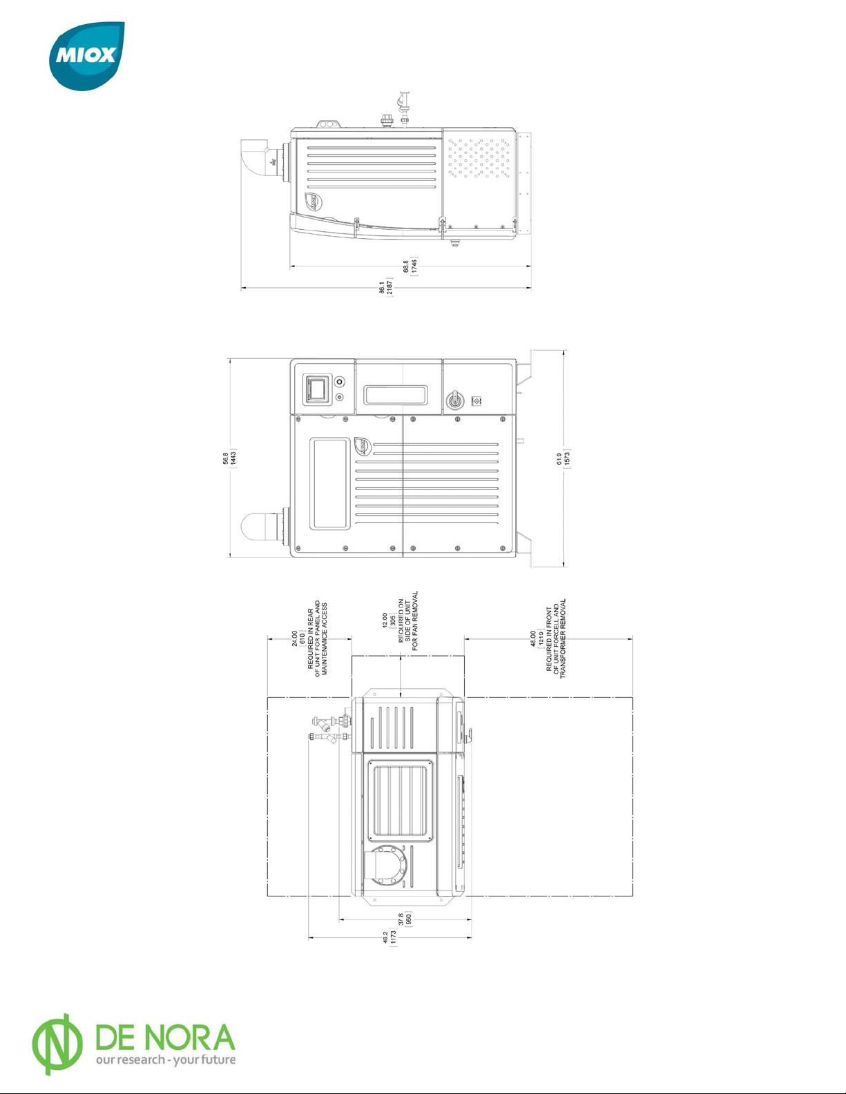
Appropriate floor-space must be identified to accommodate the OSG enclosure and
sufficient working space clearance (Figure 1-2). The enclosure is 62 in. (1.6 m) wide by 38
in. (1.2 m) deep by 69 in. (1.75 m) high. Front clearance is 48 in. (1.2 m), rear clearance
is 24 in. (0.66 m), and side clearance is 12 in. (0.30 m) from the edge of the feet.
P/N: 102-00076-G Page 8
Page 10
MIOX RIO Series Operators Manual
Figure 2 RIO Series OSG Space Requirements
P/N: 102-00076-G Page 9
Page 11

MIOX RIO Series Operators Manual
Note: Additional floor space will be required for an oxidant storage tank, brine generator, water
softener, brine pressure boost system, and depending on the installation, salt storage. Additional
floor space will also be required for the injection system and additional booster pumps
Security
MIOX equipment must be installed in a building or protected structure that provide shelter
from the weather and extreme temperature variances, and which can be locked or
otherwise secured. Physical security is required to ensure that unauthorized persons
cannot access the unit
RIO Series OSG System and Ancillary Components
Electrolytic Cell
The proprietary membrane-less electrolytic cell produces a mixture of oxidants and is
manufactured by MIOX. The RIO Series cell is configured to provide modular cell capacity
depending on the disinfectant requirement. Each MIOX cell module is configured to provide
60 lb/day Free Available Chlorine (FAC), while each HYPO cell module is rated to provide
100 lb/day FAC. Each cell can be configured from a single cell module (60 or 100 lb/day
FAC) up to a 5-module (300 or 500 lb/day FAC) cell.
The electrolytic reaction that takes place within the cell occurs under pressure (5-25 psi, 34172 kPa). The cell is equipped with a rupture disc (pressure relief port) that is designed to
rupture in the event of over-pressurization within the cell.
Water Softener
All MIOX equipment requires soft water. Hard water will cause severe damage to the cell.
Water hardness must be maintained at less than one grain/gallon (17.1 mg/L of CaCo
). The softener resin is recharged with brine from the brine generator. The correct sized
recharge meter disc is determined by water hardness.
Brine Generator
The capacity of brine generators ranges from 500 lb., manually loaded systems, to 160,000
lb. systems, pneumatically loaded from a transport truck. A mechanical float valve assembly
which monitors the brine level is included with the brine generator.
Oxidant Storage Tank
The oxidant storage tank is an integral part of an on-site generator, and is sized to meet the
injection demand at the peak hourly flow. The oxidant tank must be vented directly to the
atmosphere outside the facility.
3
Brine Pressure Boost System
A brine pressure boost system insures that sufficient brine pressure is supplied to the brine
metering pump to maintain optimal cell operation amperage. A separate electrical circuit is
required for the brine boost system.
P/N: 102-00076-G Page 10
Page 12

MIOX RIO Series Operators Manual
Tubing and Fittings
All tubing and fittings shipped by MIOX meet Schedule 80 specifications. The U.S.
specifications ensure that materials are rated for proper thickness, pressure requirements,
and temperature resistance for the specific application.
RIO Series OSG System Optional Equipment
Heater or Chiller
If the OSG feed water temperature is less than 40°F (5°C) or greater than 95°F (35°C),
damage to the electrolytic cell will occur. A water heater or chiller is recommended to bring
the water temperature into range.
Oxidant Solution Injection System
MIOX can supply injection systems to dose raw water with disinfectant. These systems
come with separate installation and operation instructions.
Water Pressure Boost System
A water pressure boost system can be included to insure minimum water pressure for OSG
operation and support of water softener regeneration. A separate electrical circuit is
required for the water pressure boost system.
P/N: 102-00076-G Page 11
Page 13
MIOX RIO Series Operators Manual
Installation
Your RIO Series OSG has been factory tested and must be properly installed by technicians
trained by MIOX or its representatives. This chapter describes the procedures for unpacking and
installing the RIO OSG and auxiliary equipment, including all requirements for plumbing and
electrical tie-ins. Specifications and conditions regarding electrical power to the unit, water
quality, water line pressure requirements, and other requirements for installation of your OSG
are discussed.
SAFETY PRECAUTIONS AND WARNINGS
Ensure that the facility and the installation are in conformance with all codes and
standards. Please refer to the MIOX Hydrogen White Paper or your local authority having
jurisdiction for more information. Untrained persons should not attempt to install or
operate MIOX OSGs.
A liquid barrier system is mandatory. Ensure that all hydrogen vent lines slope
towards the oxidant tank.
Ensure that no valves, drop legs, or P-traps are in the hydrogen vent lines. Do NOT cross connect
vent lines.
Ensure that storage tanks are labeled properly.
Disconnect power before working on units. Do not reconnect the power to the switch gear enclosure
until installation is complete.
Do not defeat or tamper with electrical interlocks or lockout mechanisms.
All MIOX units require a good earth ground. A neutral is not a substitute for a proper earth
ground. Electrical wiring to all MIOX units should be performed by a certified electrician.
The circuit feeding the MIOX OSG should be separated from other power devices.
Failure to install unit properly could result in electrical shock.
P/N: 102-00076-G Page 12
Page 14

MIOX RIO Series Operators Manual
Recommended Tools for Installation: RIO Series OSG
Mechanical Tools
• Forklift, pallet jack, or crane - unload and place equipment
• Hammer - remove crating
• Pry bar - remove crating
• 2-¾” end wrenches or equivalent - connect cell
• Channel locks or equivalent slip joint pliers - tighten plumbing connections
• Phillips screw driver - make main electrical connections
• Small flat screwdriver - connect control relay wiring
• Wire strippers
• Allen wrench set
• Tape measure
Plumbing Tools
• PVC pipe cutter or saw
• PVC pipe reamer - remove burrs from cut pipe
• Glue - use correct type for pipe material
• Primer/cleaner - use correct type for pipe material
• Teflon Ta p e
• Strap wrench
• 12” pipe wrench
Untrained Persons should not attempt to install of operate MIOX equipment.
P/N: 102-00076-G Page 13
Page 15

MIOX RIO Series Operators Manual
Receiving and Unpacking the RIO Series OSG
Your RIO Series OSG has been carefully packed to avoid shipping and handling damage. The
OSG enclosures are shipped in crated pallets. Brine generator tanks, oxidant tanks, water
softeners, and other ancillary equipment are also shipped on pallets. To safely unpack your OSG,
complete the following steps:
1. Unpack the OSG enclosure - Remove the crate from around the enclosure.
Check the enclosure for any damage that may have occurred during shipping.
2. Unpack Installation Kits - Remove the contents from the brine generator and
oxidant storage tanks. These items include the OSG installation kit, the solution
tank level switch, the softener installation kit, and the solution tank drop tube.
3. Unpa ck the water softener - Remove the water softener towers from their
packaging. Do not turn the softeners over or lay them on their sides as this will
disturb the softening resin and gravel beds inside the softener and affect softener
performance.
4. Unpack all other equipment - Remove any optional components (heaters,
chillers, injection systems, etc.) from their packaging and inspect for damage.
After completing a visual inspection, compare ordered items against what was delivered. Should
you find anything damaged or missing, please contact your MIOX sales agent or MIOX Customer
Service.
Securing the Cabinet
The RIO Series OSG is designed with mounting feet and holes for securing the enclosure to the
floor. While there are no vibrational components that would cause the system to move, good
seismic design practice and building codes in some areas require that the unit be secured to the
floor. Concrete anchors or other suitable hardware is recommended to secure the RIO OSG to
the floor. Consult local seismic codes for site-specific requirements.
P/N: 102-00076-G Page 14
Page 16
MIOX RIO Series Operators Manual
System Description
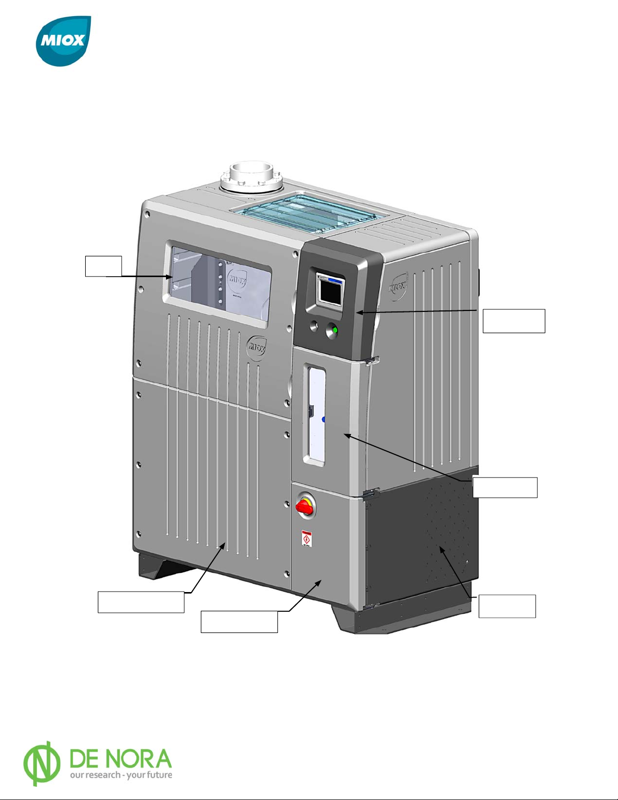
The RIO Series OSG is made up of six compartments, Controls, Switch Gear, Power Supply,
Cooling, Plumbing, and Cell (Figure 3).
Cell
Controls
Plumbing
Power Supply
Switch Gear
Figure 3 RIO Series OSG Compartments
P/N: 102-00076-G Page 15
Cooling
Page 17
MIOX RIO Series Operators Manual
Electric Connections Required for Start-Up
Normal precautions should be taken with regard to electrical components in the
vicinity of a water source.
Electrical Power Connection
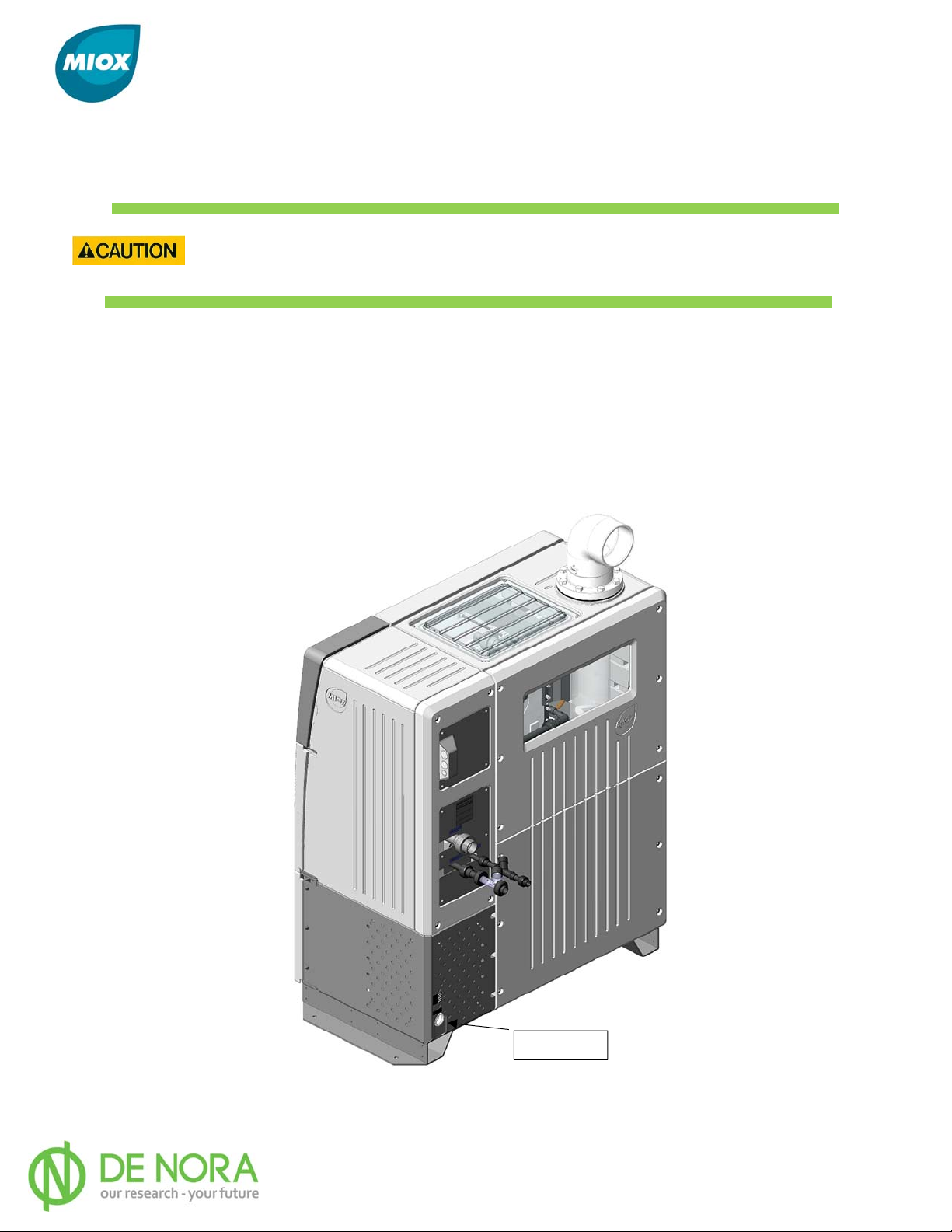
The power cable to the OSG is run through the cooling compartment into the switch gear
compartment. The power cable enters the enclosure through the back of the cooling
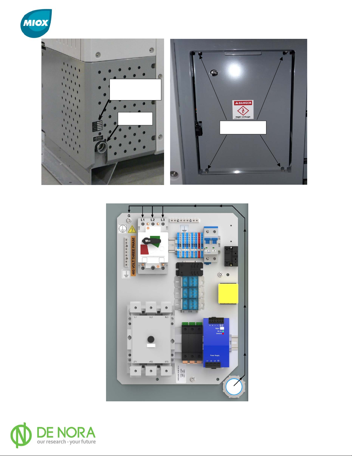
compartment into conduit (Figure 4 & 5). Remove the switch gear cover by loosening the
screws in each corner (Figure 6) and pull the cable into the switch gear compartment. Route
the power cable to the top of the switch gear and wire the switch gear (Figure 7). Replace
the switch gear cover. Do not Apply power to the system until installation is complete
Conduit
Figure 4 Rear View of RIO OSG Showing Main Power Conduit
P/N: 102-00076-G Page 16
Page 18
MIOX RIO Series Operators Manual
System Power
Ratings
Power In
4x Screws
Figure 5 Incoming Power Figure 6 Switch Gear Cover
Figure 7 Power Routing to Switch Gear
P/N: 102-00076-G Page 17
Page 19

MIOX RIO Series Operators Manual
Control System/Rear Panel Connections
The RIO Series OSG features an Allen Bradley Micrologix 1400 PLC to maintain consistent cell
control. The operator interface is an Allen Bradley Panelview Plus 600 Touch screen display.
Connection to site SCADA systems is done directly from OSG controls using the RJ45 cable.
As an optional adder, a Red Lion CSMSTRSX Modular Controller can be used as a protocol
converter which can be configured to match plant communications. The interface can be
configured to support e-mail and SMS notification if the system shuts down for a fault that
requires operator attention.
In addition to providing internal control of the OSG, the RIO Series control system provides
connectivity to various external inputs and outputs (Figure 8).
A Modbus/Ethernet IP is built in PLC as a standard. For other communication options
available, contact MIOX.
Figure 8 Rear Panel Connections
P/N: 102-00076-G Page 18
Page 20
MIOX RIO Series Operators Manual
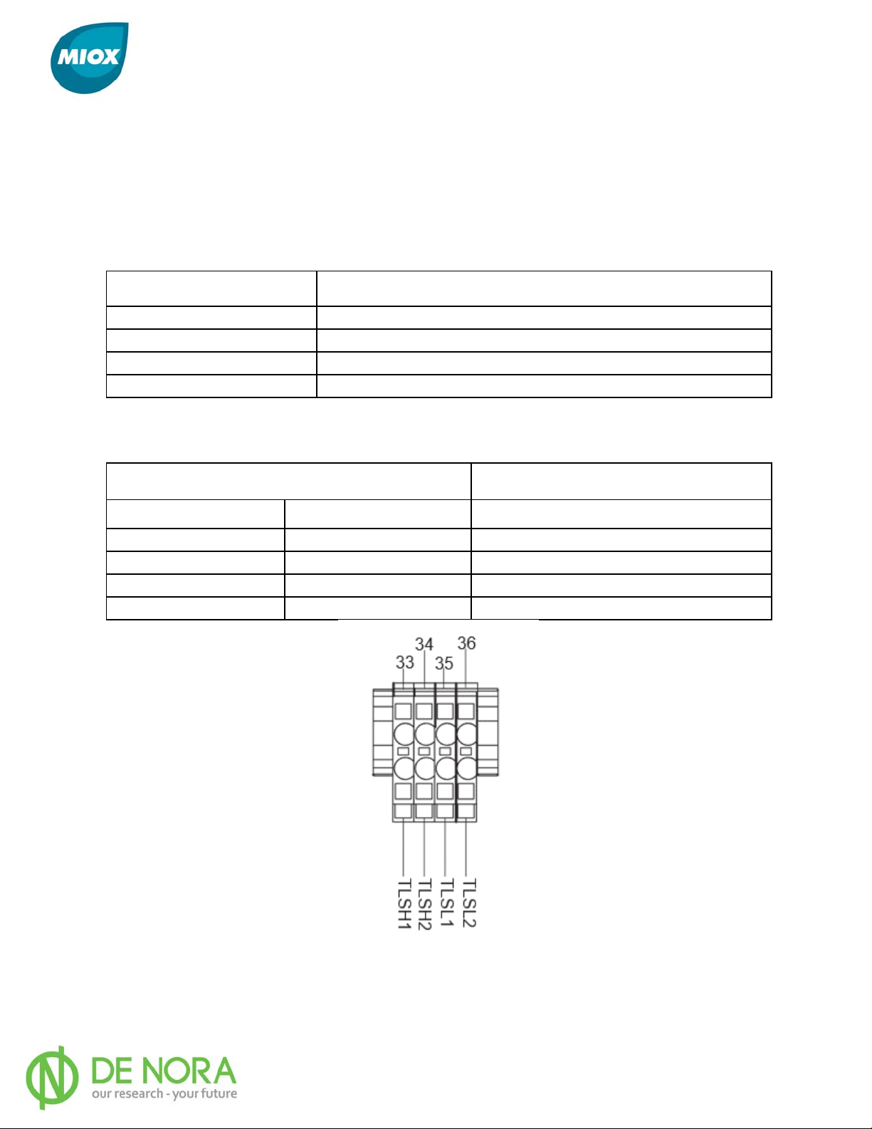
Tank Level Inputs
The tank level connector provides field connection points for external floats, the dry contact
outputs on a tank level controller, or the dry contact outputs of a plant PLC or other control
device. Tables 1 and 2 provide descriptions for each terminal.
Table 1 Tank Level Connector Name and Description
Connection Name
TLSL1 Lower tank level input 24VDC-CLOSED 0VDC-OPEN
TLSL2 +24VDC source of lower tank level input
TLSH1 Upper tank level input 24VDC-CLOSED 0VDC-OPEN
TLSH2 +24VDC source of upper tank level input
Table 2 Tank Level Status
INPUT STA
Lower Level Input
Closed Closed Tank is empty - Turn ON
Open Open Tank is full - Turn OFF
Open Closed Stand-by - Stays Off or ON
Closed Open Fault Condition - Turn OFF
TES
Upper Level Input
Signal
Description
SYSTEM
System Action
Figure 9 Tank Level Connector
P/N: 102-00076-G Page 19
Page 21
MIOX RIO Series Operators Manual
Auxiliary Relay Connection
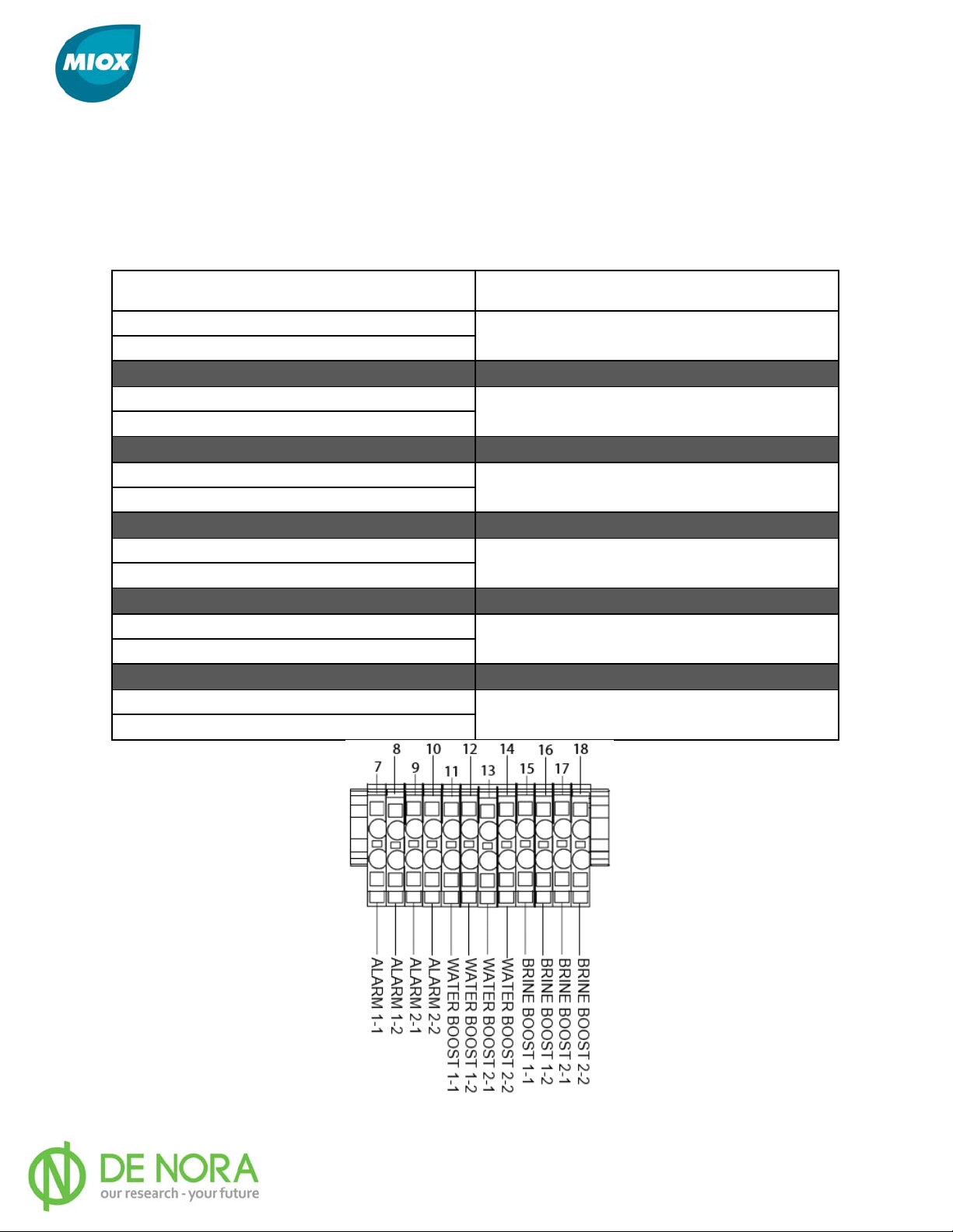
The auxiliary relay connector provides field connection points for three auxiliary relays,
alarm, brine boost, and water boost. Each relay has two sets of normally open contacts. The
contacts are rated for 277 VAC at 30 Amps or 28VDC at 20 Amps. Table 3 provides the
description for each connection.
Table 3 Auxiliary Relay Connector Name and Description
Connection Name
Alarm 1-1
Alarm 1-2
Alarm 2-1
Alarm 2-2
Water Boost 1-1
Water Boost 1-2
Water Boost 2-1
Water Boost 2-2
Brine Boost 1-2
Brine Boost 2-2
Brine Boost 1-2
Brine Boost 2-2
Description
Contacts close when system shuts down
for a hard fault
Contacts close when system shuts down
for a hard fault
Contacts close when system starts up
(running)
Contacts close when system starts up
(running)
Contacts close when system starts up
(running)
Contacts close when system starts up
(running)
Figure 10 Auxiliary Relay Connector
P/N: 102-00076-G Page 20
Page 22
MIOX RIO Series Operators Manual
Auxiliary 24V Power Connection
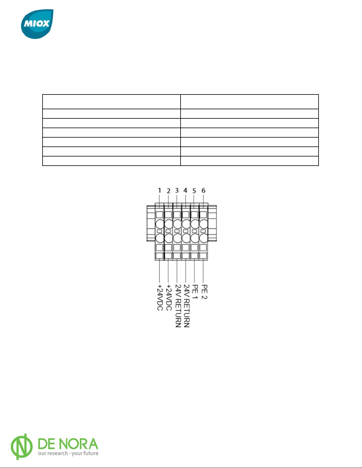
The auxiliary power connector provides field connection points to provide 24V power to the
auxiliary relays. Current is limited to 1 AMP and is fused internally. Table 4 provides the
description for each terminal
Table 4 Auxiliary 24V Power Connector Name and Description
Connection Name
Description
+24VDC +24 volts DC power
+24VDC +24 volts DC power
24V Return Return connection for 24VDC power
24V Return Return connection for 24VDC power
PE1 Physical Earth connection
PE2 Physical Earth connection
Figure 11 Auxiliary 24V Power Connector
P/N: 102-00076-G Page 21
Page 23
MIOX RIO Series Operators Manual
Dilution Air Connection
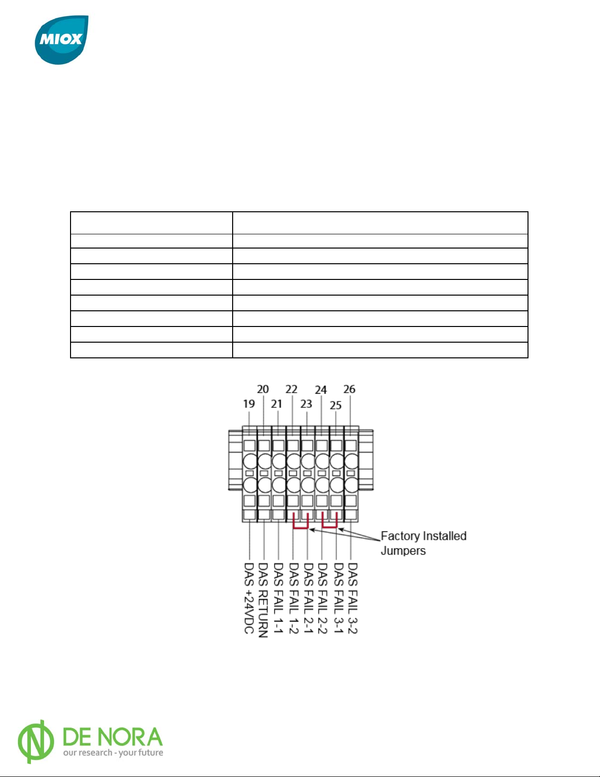
The dilution air connector provides field connection points for an auxiliary dilution air system
and/ or associated external dilution air system sensors. The connections supported include a
MIOX external dilution air enable, MIOX external dilution air system failure input, and two
other failure inputs. The failure inputs can be connected to either external differential
pressure switches or an external flow switch with dry contacts. Pins 19 and 20 (Figure 12)
should be wired to the Dilution Air Panel Relay to turn on the auxiliary panel. Table 5
provides the description for each terminal.
Table 5 Dilution Air Connector Name and Description
Connection Name
DAE +24 VDC
DAE Return Return for enable
DAS Fail 1-1 Failure Input 1; 24VDC OK - 0 VDC FAIL
DAS Fail 1-2 +24VDC source of Failure Input 1
DAS Fail 2-1 Failure Input 2; 24VDC OK - 0 VDC FAIL
DAS Fail 2-2 +24VDC source of Failure Input 2
DAS Fail 3-1 Failure Input 3; 24VDC OK - 0 VDC FAIL
DAS Fail 3-2 +24VDC source of Failure Input 3
+24VDC enable signal for MIOX external dilution air
Description
system
Figure 12 Dilution Air Connector
P/N: 102-00076-G Page 22
Page 24
MIOX RIO Series Operators Manual
Hydrogen/Hardness Connections
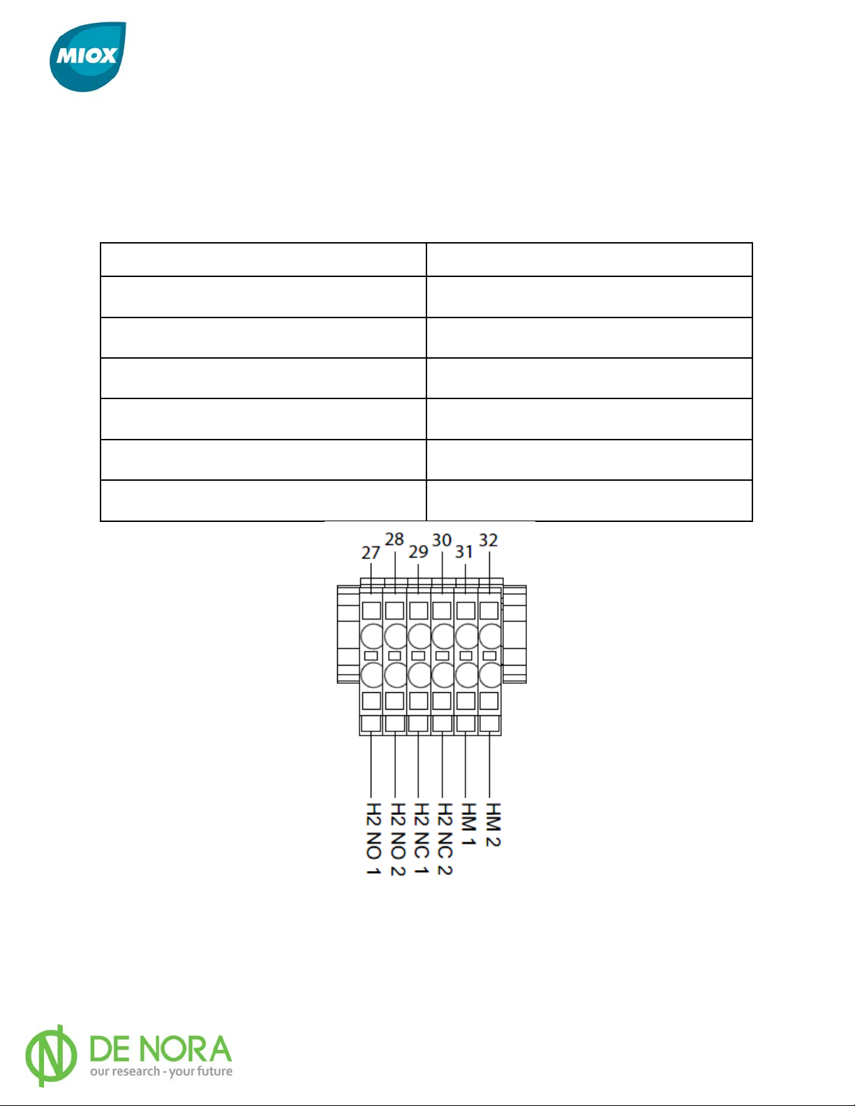
The Hydrogen/Hardness connector provides field connection points for an external hydrogen
monitor and/or an external hardness monitor. The hydrogen monitor inputs require both
normally closed and normally open dry contacts. The hardness monitor input only requires
normally closed dry contacts. Table 6 provides the description for each terminal.
Table 6 Hydrogen/Hardness Connector Name and Description
Connection Name
H2NO1
H2NO2
H2NC1
H2NC2
HM1
HM2
Description
Normally open input; OPEN = OK,
CLOSED =
Normally open input; OPEN = OK,
CLOSED =
Normally closed input; CLOSED = OK,
OPEN
Normally closed input; CLOSED = OK,
OPEN
Hardness monitor input; 24VDC = OK,
+24VDC source of hardness monitor input
FAIL (Safety Relay)
FAIL (Safety Relay)
=
FAIL (Safety Relay)
=
FAIL (Safety Relay)
0 VDC =
FAIL
Figure 13 H2/Hardness Connector
P/N: 102-00076-G Page 23
Page 25
MIOX RIO Series Operators Manual
Ethernet Connection
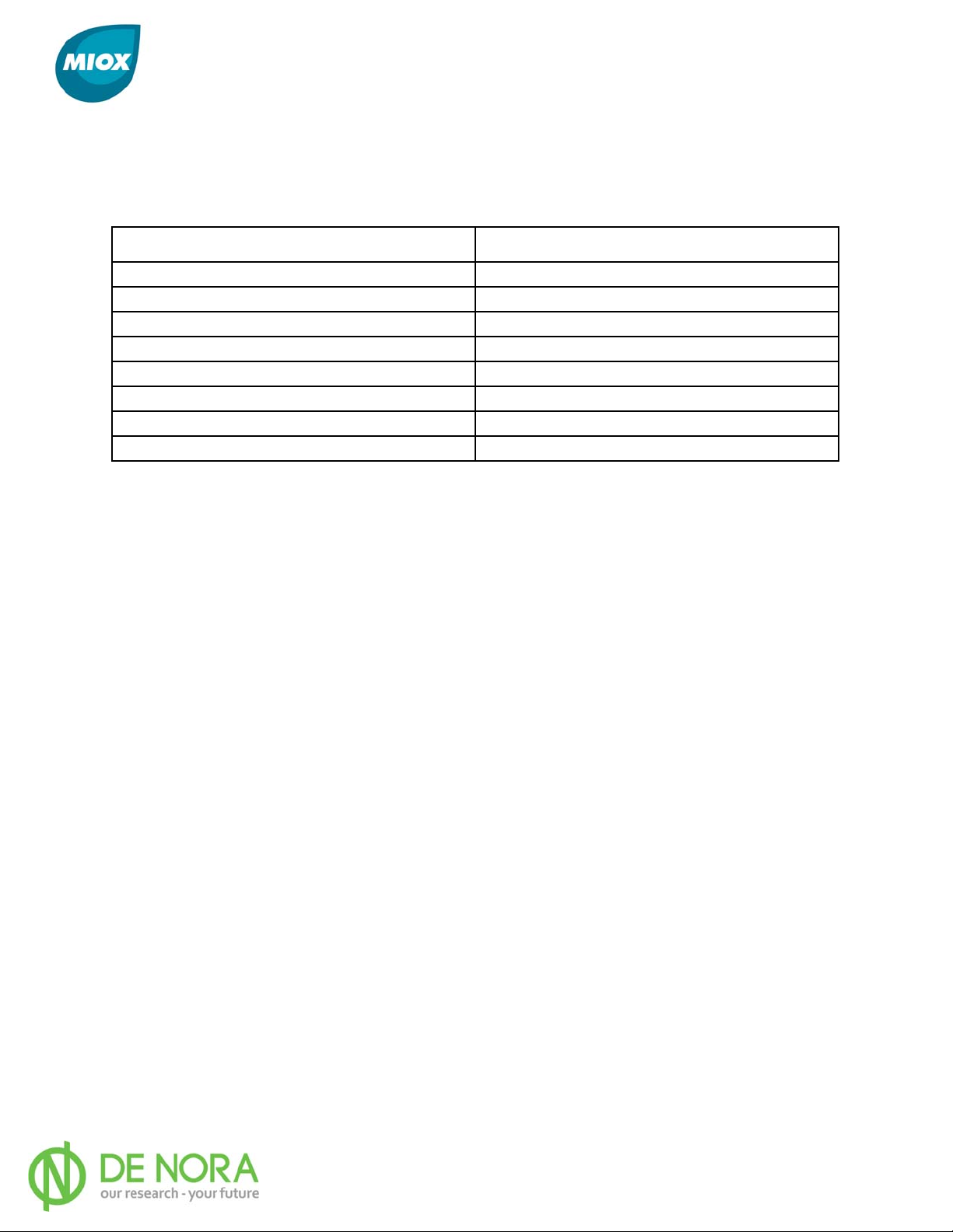
The Ethernet connector provides connection to site SCADA systems. Table 7 provides the
pin-out for the connector.
Table 7 Ethernet Connector Pin-Out
Pin
Pin Name
1
2
3 Rx+
4 not used
5 not used
6 Rx-
7 not used
8 not used
Tx+
Tx-
P/N: 102-00076-G Page 24
Page 26
MIOX RIO Series Operators Manual
Plumbing Connections Required for Startup
All water and brine systems are compatible with schedule 80 PVC. MIOX strongly
recommends schedule 80 CPVC for all mixed-oxidant or sodium hypochlorite solutions and
hydrogen venting. Where possible, all connections should be solvent weld rather than
threaded to prevent the possibility of leaks. All piping should be supported at 3 - 4 ft. (1 m)
intervals. Isolation valves should be included on all inlet lines external to the RIO Series
OSG.
Feed Water Connection
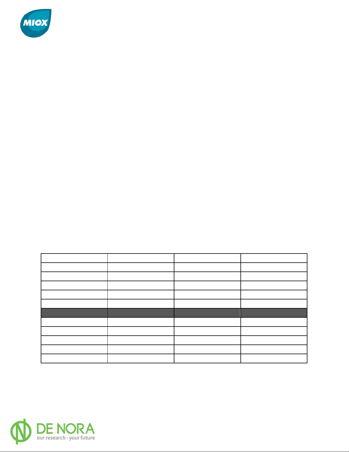
Feed water requirements for the RIO Series OSG are given in Table 8. Additional feed water
is based on water softener requirements. Consult water softener specifications for required
flow rates. A minimum of 35 psi (242 kPa) feed water pressure at the OSG is required to
ensure stable flow and a continuous supply of 5-25 psi (34-172 kPa) brine feed to the
electrolytic cell. To protect against low water pressure, an auto adjusting flow control valve is
included in the piping manifold to compensate for inconsistent flow and pressure fluctuations.
It uses a turbine flow sensor that sends pulses to the PLC when the turbine is spinning.
Based on the rate of the pulses, the system can calculate the feed water flow rate and adjust
the flow control valve accordingly. This setting is critical for proper oxidant production, cell
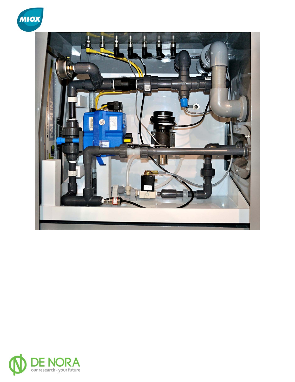
cooling, and other key operating parameters. A liquid filled pressure gauge is included in the
plumbing compartment to visually monitor the cell pressure (Figure 14). Maximum supply
pressure to the RIO Series OSG should not exceed 100 psi (689 kPa). For supply pressure
above 100 psi (689 kPa), a pressure regulator must be added to lower the pressure to a
range of 35-100 psi (242-689 kPa).
Table 8 Feed Water Requirements
Cell Module
M1 75 1.25 283.5
M2 150 2.50 567.0
M3 225 3.75 850.5
M4 300 5.00 1134.0
M5 375 6.25 1417.5
H1 75 1.25 283.5
H2 150 2.50 567.0
H3 225 3.75 850.5
H4 300 5.00 1134.0
H5 375 6.25 1417.5
GPH
GPM
LPH
P/N: 102-00076-G Page 25
Page 27
MIOX RIO Series Operators Manual
Figure 14 Plumbing Enclosure
The feed water connection to the RIO Series OSG comes from the water softener. The
recommended feed water temperature should be between 55-80 °F (12-27 °C) for optimal
efficiency. The allowable feed water temperature is between 40-95 °F (5-35 °C). The feed
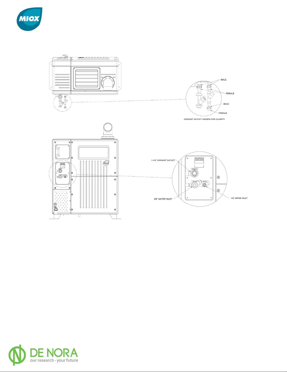
water connection is ¾” schedule 80 PVC. The unit is equipped with a ¾” PVC male union
half and a ¾” Y-strainer assembly. Proper connection is accomplished with a ¾” PVC female
union half mating to the male half (Figure 15). Before connecting the water supply to the
OSG, flush water through the softener until the water is clean and clear.
Brine Feed Connection
The brine feed connection to the RIO Series OSG is ½” schedule 80 PVC. The OSG is
equipped with a ½” PVC male union. A Y-strainer assembly with a ½” PVC female union is
provided to attach to the brine inlet. Proper connection is accomplished with the ½” PVC
female union half mating to the male half (Figure 15).
P/N: 102-00076-G Page 26
Page 28
MIOX RIO Series Operators Manual
Note: On initial start-up, cell replacement or when brine plumbing connections are modified,
air is introduced to the brine line. This air must be removed for proper operation of the
brine pump. Air locks in the brine line will prohibit consistent brine flow to the cell.
Figure 15 Feed Water, Brine, Y-strainer, and Oxidant Union Connections
Oxidant Discharge
The oxidant discharge connection from the RIO Series OSG is 1¼” schedule 80 CPVC but
increases in size to 1½”. The OSG is equipped with 1½” CPVC male union half. Proper
connection is accomplished with a 1½” CPVC female union half mating to the male half
(Figure 15).
MIOX supplies a three-way valve to allow for sampling of the disinfectant solution to verify
system performance. MIOX also supplies a check valve and strongly recommends installing
the valve on the oxidant discharge line. The valve should be installed between the RIO
Series OSG cabinet and the three-way valve sample port to prevent the backflow of
oxidant/hypochlorite into the electrolytic cell.
P/N: 102-00076-G Page 27
Page 29

MIOX RIO Series Operators Manual
Do not use any valves in the mixed-oxidant or sodium hypochlorite lines other
than the three-way valve provided by MIOX. These valves have an open center
configuration that prevents the blockage of flows from the cell. Failure to use
MIOX supplied three-way valves may void the warranty.
Drains
The cell and plumbing compartments are the only two areas in the OSG that have the
potential for a water leak. Both compartments are equipped with low point drains that will
drain directly to the floor. The cell compartment drain pipe is plumbed through the power
supply compartment floor. The plumbing compartment drain pipe is plumbed through the
cooling compartment floor. The drains from these compartments should only flow in the
event of a malfunction that will be evident from liquid underneath the enclosure. If this
condition is noticed, immediately shut down the system, diagnose, and correct the leak.
P/N: 102-00076-G Page 28
Page 30
MIOX RIO Series Operators Manual
Brine Generator Installation (Optional)
Plumbing Connections
Place the brine generator on a flat surface that is capable of handling the load of a fully
loaded tank. A 1,000 gallon tank can hold up to 9,000 lbs. of salt. Sweep the floor prior to
installation. Debris left under a tank can permanently damage the tank. Rotate the tank to
align inlet and outlet fittings that best suit the installation. Plumb softened water to the inlet
of the tank. It is recommended that an isolation valve be installed on the water line prior to
the tank to assist with maintenance. Plumb the overflow fitting to a drain. Verify the
overflow line has an adequate air gap to prevent cross contamination of the brine generator.
Plumb the outlet fitting (Figure 16).
Note: Outlet plenum should be installed before float assembly.
Note: Use Teflon tape on threaded plumbing connections.
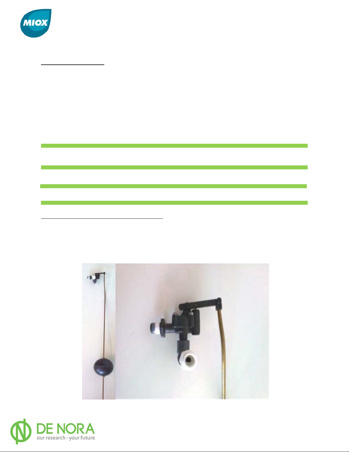
Brine Tank Float and Spray Ring Assembly
MIOX has adapted an off-the-shelf float valve and spray ring assembly for providing
saturated brine to the on-site generator. Kinetico® provides KCBS (Kinetico® Central Brine
System) which includes a float valve assembly with a 28” height adjustment range to allow
for a broader range of tank fill levels.
Figure 16 Float Valve Assembly and Detail
P/N: 102-00076-G Page 29
Page 31
MIOX RIO Series Operators Manual
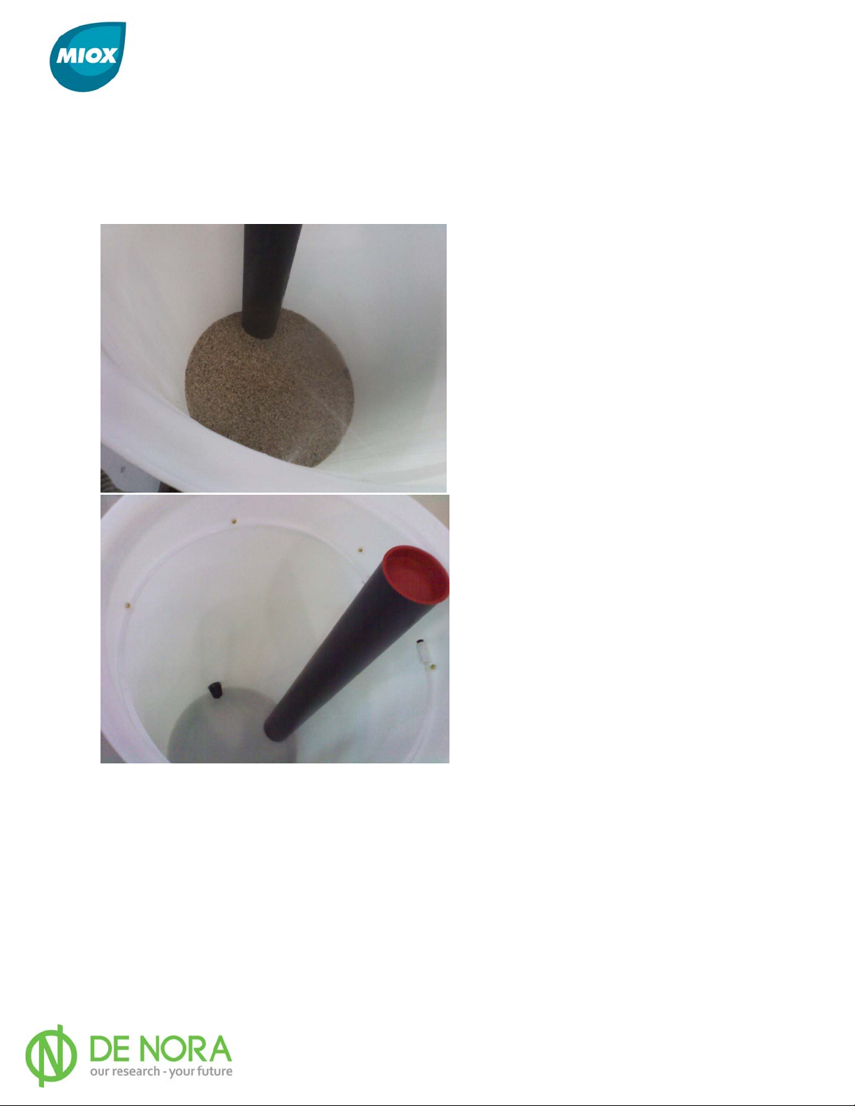
The spray ring assembly provides a more consistent means of mixing the salt and water to
meet the brine saturation requirement. The spray ring at the top of the tank eliminates
possibility of channeling (or short circuiting) the water through the outlet of the tank. Adding
a quartz rock bed at the bottom the tank also reduces the possibility of brine channeling for
any application. Figure 17 provides an illustration of the spray ring assembly installed in a
quartz rock bed (left) and tank assembly without quartz rock.
Figure 17 Internal View Float Valve Assembly and Detail
For instances where the float needs to be removed, turn off the water to the system.
Remove the (red) cap on top of the stillwell. Unscrew the 3/8” PVC coupler that mates to the
feed water line and the black threaded flange connection protruding through the tank wall.
Unscrew the coupler that mates to the plastic spray ring. The float valve can now be pulled
out the stillwell. The float itself, can be unscrewed at the clevis hinge that mates with the
open/close poppet valve. To re-install the valve assembly, repeat step in reverse order,
making sure to use Teflon tape for replacing all NPT connections. Replace red cap and return
water supply. Verify float does close once high level is reached and system is not flowing
water.
P/N: 102-00076-G Page 30
Page 32

MIOX RIO Series Operators Manual
Quartz Rock
In order to accommodate various salt types, MIOX provides a cross-shaped, slotted pipe
manifold. Thread the manifold into the bottom tank adapter. Place 7 inches of ½” x ¼” NSF
quartz rock in the bottom of the tank. Rake it flat and cover the slotted pipe manifold. Place
5 inches of ¼” x ⅛” NSF quartz rock on top of the first layer of quartz rock. Rake flat.
Brine Silos
Brine silos have their own specific installation instructions. Follow the manufacturer’s
recommendations for handling and installation.
P/N: 102-00076-G Page 31
Page 33
MIOX RIO Series Operators Manual
Brine Pressure Boost System Installation (Optional)
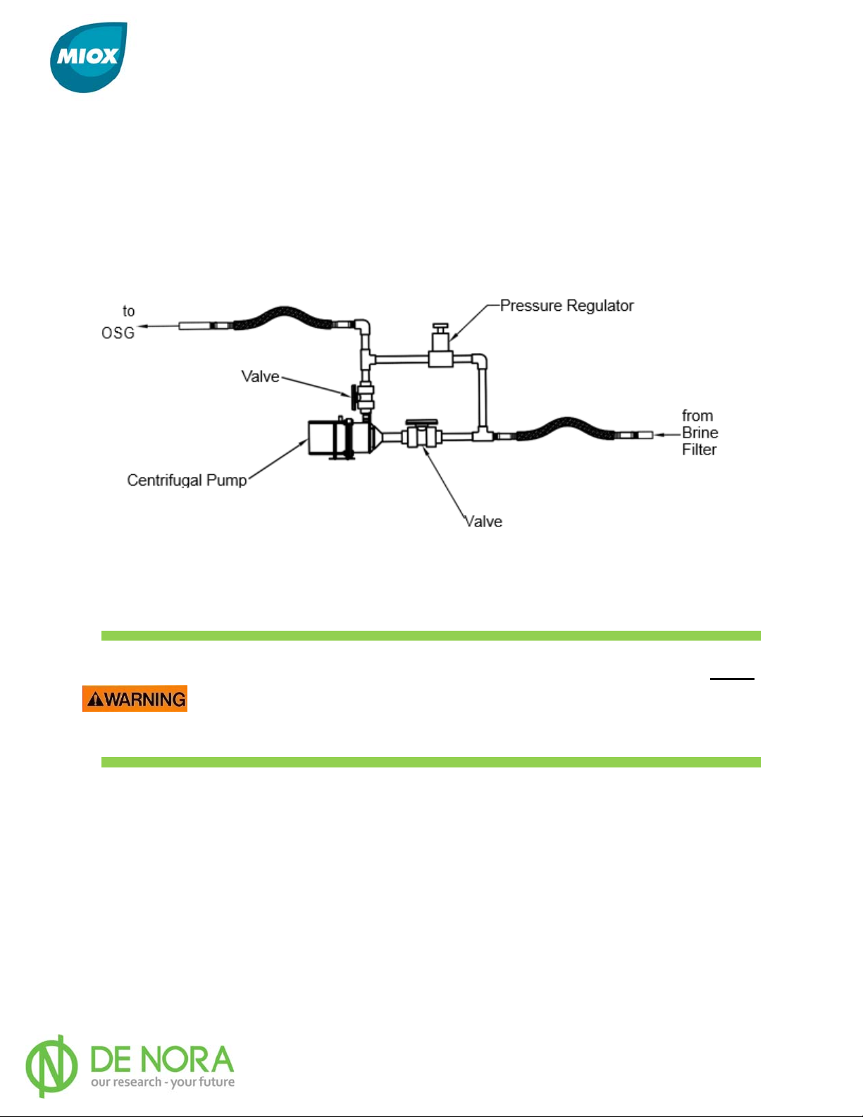
The brine boost system ensures that sufficient brine pressure is supplied to the OSG to
maintain optimal cell amperage and is required on all RIO Series OSG installations. A brine
pressure boost system includes a centrifugal booster pump and pressure relief valve/back
pressure valve (Figure 18). A separate electrical circuit is required for the brine boost
system. The brine boost pump should be mounted as low as possible in relation to the brine
generator to ensure a flooded suction.
Figure 18 Brine Pressure Boost System
Oxidant Storage Tank Installation
THE SPECIFICATIONS IN MIOX ’s Hydrogen Safety White Paper MUST
be read before installation of oxidant storage tanks begins. ANY
DEVIATION FROM THESE SPECIFICATIONS MAY RESULT IN DAMAGE
TO PERSON OR PROPERTY.
The oxidant storage tank is designed to act as a holding tank for the oxidant solution and
consists of the tank, drop tube assembly, vents, outlet valve assembly, and safety placards.
A level switch or pressure transducer is also included depending on the tank’s capacity.
Ventilation Requirements
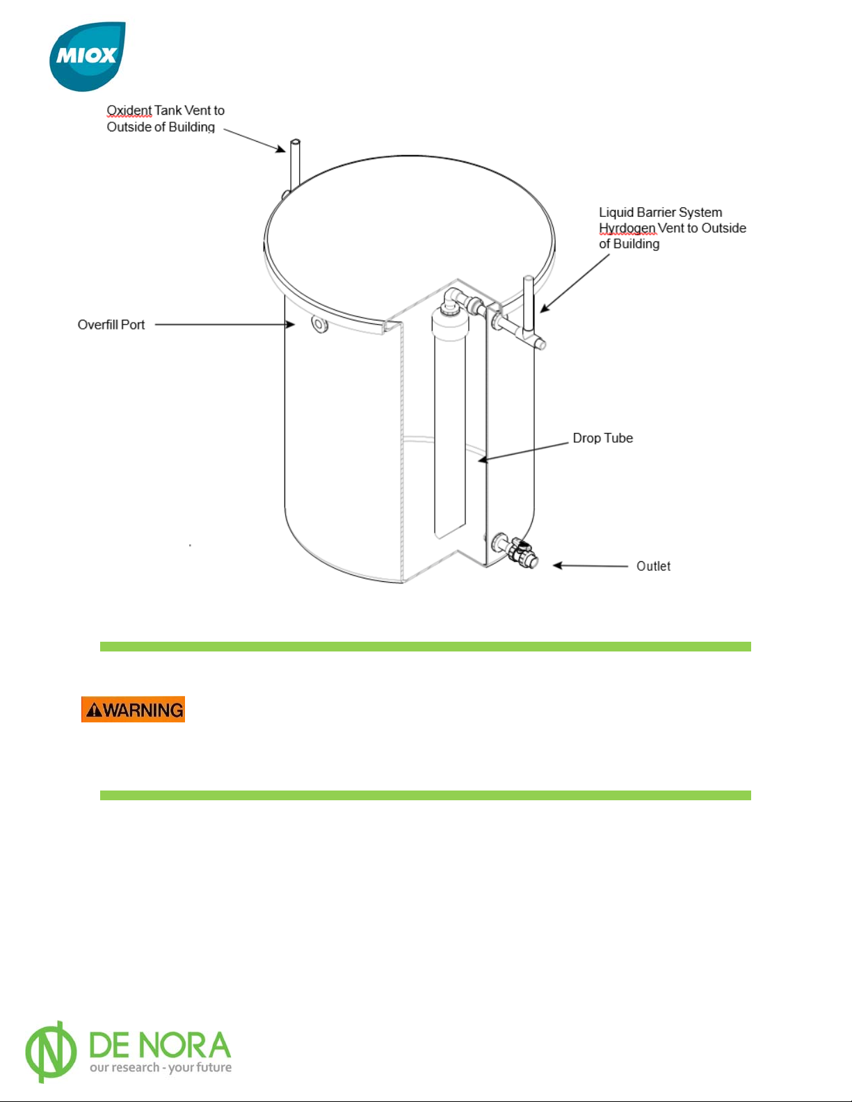
MIOX oxidant tanks require a drop tube and two vents, a Liquid Barrier System (LBS)
hydrogen vent and Oxidant Tank hydrogen vent (Figure 19). A drop tube assembly and LBS
vent assembly are shipped with the oxidant tank. The user is responsible for supplying CPVC
piping to attach to the top of the LBS vent tee and for the Oxidant Tank Vent. Vents must be
installed with a minimum drain slope of 0.5 in. per foot (1.3 cm per meter), sloping
downward from the main vent towards the tank. If the oxidant tank is not supplied by MIOX,
a drop tube assembly and LBS vent assembly must be fabricated on-site.
P/N: 102-00076-G Page 32
Page 34
MIOX RIO Series Operators Manual
All oxidant tanks must have a properly installed LBS Vent and Oxidant
Tank Vent to operate safely. An optional Dilution Air System can be
supplied upon request and on large installations, a combination stand
pipe and Dilution Air System can be used. Refer to MIOX ’s
Safety White Paper
Figure 19 Oxidant Tank Vents
Hydrogen
for additional details.
P/N: 102-00076-G Page 33
Page 35
MIOX RIO Series Operators Manual
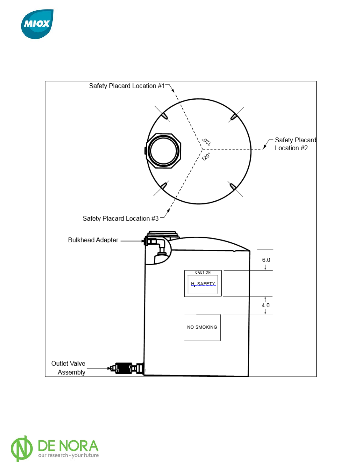
Safety placards are required on oxidant tanks and are attached to all oxidant tanks shipped
directly from MIOX. Oxidant tanks shipped directly from the tank manufacturer must have
the MIOX supplied safety placards attached to the outside wall of the oxidant tank (Figure
20).
Figure 20 Oxidant Storage Tank with Safety Placards
P/N: 102-00076-G Page 34
Page 36
MIOX RIO Series Operators Manual
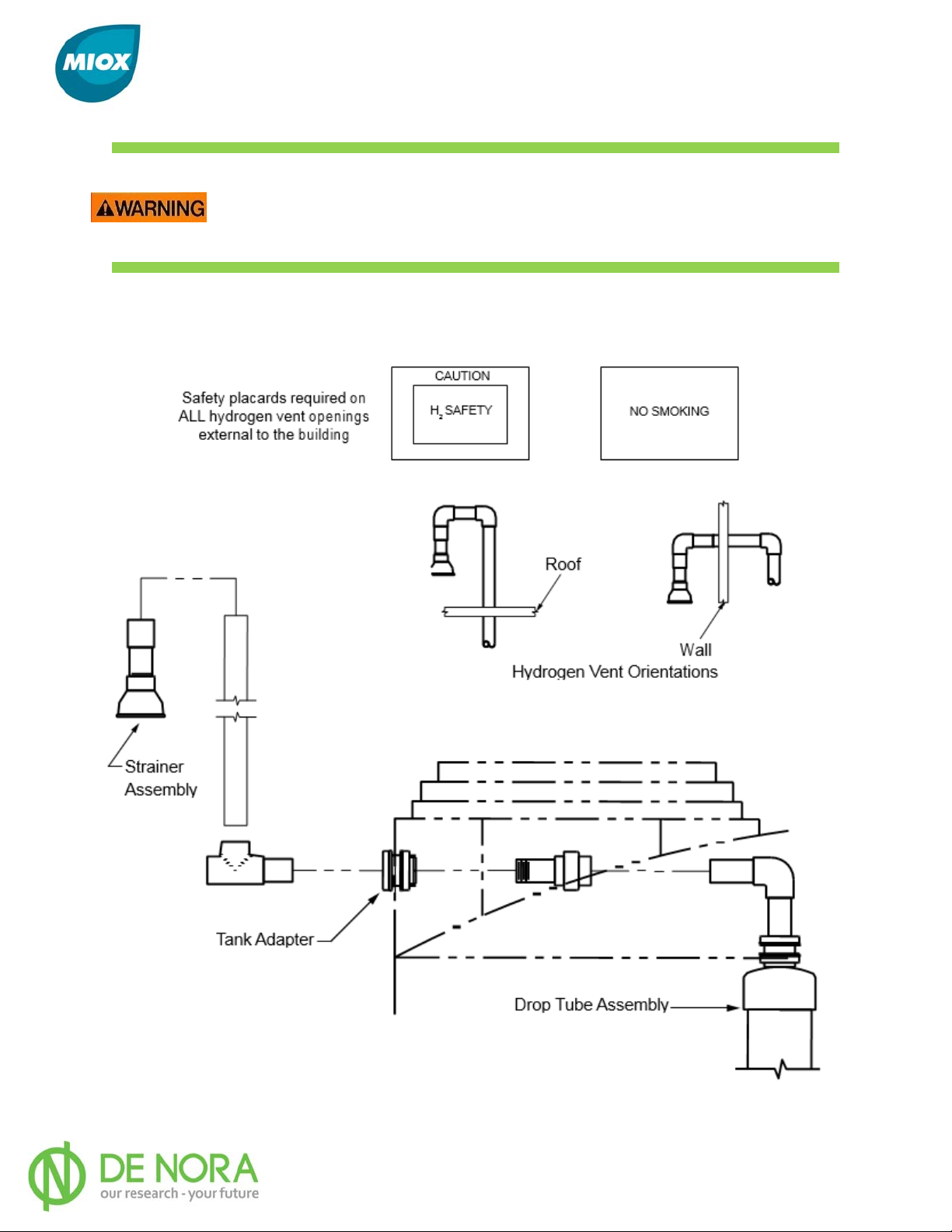
The plumbing and ventilation requirements explained in MIOX ’s
Hydrogen Safety White Paper
and this manual must be followed
explicitly to ensure proper hydrogen venting.
MIOX oxidant tanks require that they be vented to the atmosphere outside the facility.
Proper configuration of vent assemblies (Figure 21) is vital to ensure safety.
Figure 21 Ventilation Requirements
P/N: 102-00076-G Page 35
Page 37
MIOX RIO Series Operators Manual
Level Switch Installation
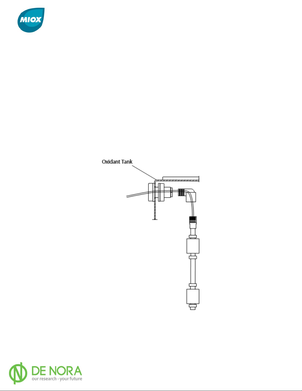
For MIOX-supplied oxidant storage tanks, the level switch is shipped loose in the tank. If the
oxidant storage tank is not shipped with the RIO Series OSG, the switch is shipped
separately. The switch is designed to operate with the RIO Series OSG. To install the level
switch in the tank, complete the following steps (Figure 22):
1. Wrap the male end of the street elbow with Teflon tape and connect it inside the
solution tank into the ½” bulkhead adapter at the top of the tank.
2. Feed the electrical cord through the elbow and out of the tank.
3. Seal the male end of the liquid level switch with Teflon tape and screw it into the
female end of the street elbow. Hand tighten only.
The wire from the level switch is run to the connector on the rear panel of the OSG (Figure
8) and wired per Table 1.
Figure 22 Level Switch Installation
PLC controlled OSG’s can be controlled in either local or remote control mode. In local
control mode the system is controlled by two sets of contacts which are typically embedded
in a float switch. If both contacts are closed, the systems starts and runs. If both contacts
are open, the system stops running and goes into standby. In remote control mode, the
P/N: 102-00076-G Page 36
Page 38
MIOX RIO Series Operators Manual
system uses electronic commands to start and stop. There are three different commands
you can send to the system. The first command is used to tell the system to run or stop.
The other two are used together to makes sure the connection between the OSG and
network controller is functioning. The first of the two commands tells the system to count to
ten (10). The second command resets the system counter to zero (0). If the systems
counter reaches ten (10) before it receives the second command, the system will fault.
Functionally this means the network controller must send the reset command at least once
every ten (10) seconds to prevent the system from faulting.
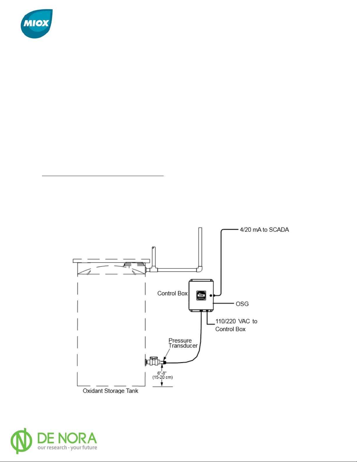
Pressure Transducer Installation (Optional)
The pressure transducer system consists of GF Signet Pressure Transducer and a control
box. The control box is designed to mount on a wall and must be in an indoor location no
more than 75 ft. (22.9 m) from the oxidant storage tank. All external wiring from the control
box is provided by the customer. The control box requires 110 or 220 VAC. Refer to
Manufacturer’s Manual for installation guidelines
Recommended Tools and Test Equipment
Small pocket flat head screwdriver
Diagonal Cutters
Wire Strippers
Digital mulit-meter
Figure 23 Pressure Transducer Assembly
P/N: 102-00076-G Page 37
Page 39
MIOX RIO Series Operators Manual
Oxidant Tank Lid
The oxidant tank lid should cover the tank during operation, which helps reduce volatilization
and extends the life of the oxidant solution.
Feed Line Connection/Injection System
The oxidant tank outlet valve is located at the bottom of the oxidant tank. This oxidant tank
outlet provides oxidant solution to the water system for disinfection purposes. Oxidant
solution can be injected into the water system with a chemical feed pump or a venturi
injector that is typically mounted in a side-stream of the main water line. The injection
system should be designed by a qualified engineer, MIOX distributor, or salesperson. Refer
to Injection System Manufacturer’s Manual for Installation Guidelines
Overflow Port
An overflow port connection fitting is provided at the top of the oxidant tank. This should be
piped to a drain or other suitable discharge outlet with 1” schedule 80 CPVC pipe. For sites
with two oxidant tanks installed, the overflow ports should be piped to each other with a
common drain. If the customer elects not to run the overflow drain, then the outlet must be
plugged to prevent gasses in the storage tank from venting to the room.
Do not pipe brine and oxidant tank overflows into the same drain header as the
water softener discharge. Install separate drain headers to a common floor
drain. If all systems are tied into the same drain header, high back- pressure
from the water softener discharge drain can backflow up the brine and oxidant
tank overflow lines and contaminate the brine generator and oxidant tank with
softener wastewater. This will result in brine tank flooding, calcium carbonate
contamination of the electrolytic cell, and dilution of the oxidant.
If a dilution air system is used, the overflow port must be equipped
with an internal drop tube to prevent the forced air leaving the tank
through the overflow port.
P/N: 102-00076-G Page 38
Page 40

MIOX RIO Series Operators Manual
Cell Installation and Removal
All RIO systems are shipped with the Cell pre-installed. Instances when the cell must be
removed or installed, the procedure below should be followed:
Removal
Ensure the OSG is in STOP mode and isolate 400-480 VAC power from the unit. Remove the
cell lead guards by unscrewing the fasteners at the cell cover. Loosen and remove the cell
leads from the cell buss bars. Drain the cell prior to disconnecting the plumbing connections
to the cell. Cell draining is accomplished by utilizing the blue handle valve located on the
inlet plumbing to the cell. Slightly open the oxidant outlet union located at the top of the
cell. Open the blue handle drain valve which will begin the cell draining. Use a 5-gallon
bucket to collect solution from cell. Unscrew both oxidant outlet union and water inlet union
to the cell. Remove the front and rear hardware on the all thread rod that is attached to the
top mounting bracket. Make notice of the nylon washers that isolate the bracket from the
steel washer. The nylon washer will have to be replaced when the cell is re-installed.
Remove the top front cell bracket by unscrewing the horizontal bolt and nut. Save hardware
for re-install. At this point a M4/H4 and M5/H5 cell can be removed from the front. To
remove M1/H1 – M3/H3, two additional front, bottom cell brackets will have to be removed
from the uni-strut.
A forklift or equivalent lifting mechanism must be utilized when transferring the cell. The cell
can weigh 80-400 lbs. (36-181 kg) for 1-module to 5-module cells, respectively. Take
special precaution to lift the cell in locations that are identified with lifting labels on the cell.
Do not lift the cell using the buss bars or cell inlet manifold.
Lastly the all-thread rod needs to be removed from the top of the cell if the cell is going to
be replaced. Remove all the nuts and washers, noting position and locations so that the allthread rod can be installed on the new cell.
Installation
Be certain the cell is oriented so the inlet side is on the left-hand side of the enclosure
(based on front view). Insert the cell vertically onto the cell support uni-struts inside the cell
compartment. The cell should be placed so that the rear cover is resting against the two rear
bottom cell support brackets. For M1/H1-M3/H3, reinstall the two additional front bottom
cell brackets on to the uni-strut.
For permanent installations where the RIO OSG will not move, re-connecting the cell to the
top mounting bracket is not required. The cell must be connected to the top cell mounting
bracket if there is a potential for the OSG to move. Make certain the all-thread rod is
replaced secured to the top cell bracket per its original mounting configuration. Reconnect
the top front cell bracket so the cell can be connected to the mounting bracket. Be certain
the nylon washers that isolate the bracket from the steel washer are installed. Reconnect
inlet and outlet union fittings to the cell. Close drain (blue handle) valve on rear of unit.
Reconnect cell leads to cell bus bars utilizing the Electrical Connection and Cell Lead/Bussbar
Connections sections in this Manual. Fasten the cell lead guards to the cell covers.
P/N: 102-00076-G Page 39
Page 41
MIOX RIO Series Operators Manual
Electrical Connections
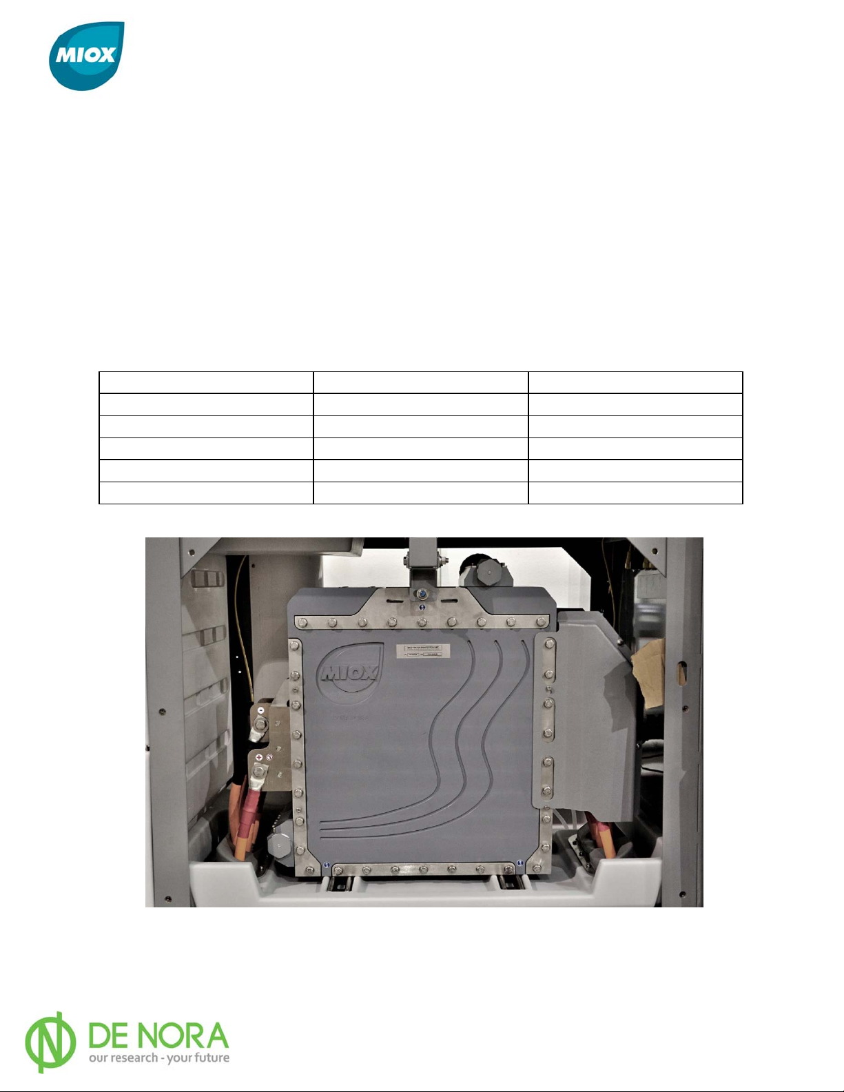
Connection of the cell electrical leads to the cell is accomplished by matching the red leads to
the anode or positive buss bars and the black leads to the cathode or negative buss bars.
Electrical connections are determined by number of cell modules in the cell assembly. Each
electrode/ buss bar must be connected to an electrical lead on both sides of the cell (Figure
24). The anode or positive buss bar is always the first electrode facing the front of
the unit. The cathode or negative buss bar is the next electrode behind the anode. This
alternating electrode configuration will continue depending on the number of cell modules.
Table 9 identifies the number of electrical connections (+/-) based on the number of
modules.
Table 9 Electrical Connections Per Cell Module
Cell Configuration # of Red (+) Leads # of Black (-) Leads
M1/H1 2 2
M2/H2 4 2
M3/H3 4 4
M4/H4 6 4
M5/H5 6 6
Figure 24 Cell Lead Connections
P/N: 102-00076-G Page 40
Page 42
MIOX RIO Series Operators Manual
Cell Lead/Bussbar Connection
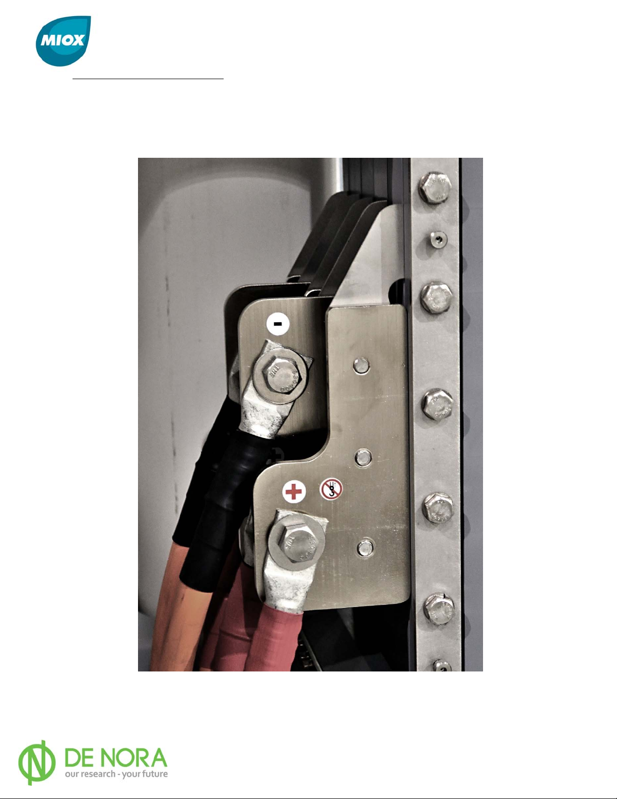
Apply electric joint compound to the cell lead lug and the ½” bolt. Align the cell lead lug with
the hole on the buss bar and fasten with the ½” bolt, washers, and nut. The bolt head should
face the front of the cell followed by a split washer, flat washer, cell lead, bussbar, flat
washer, and nut (Figure 25). Tighten bolt to 40 ft./lbs. ± 2 ft./lbs. (54 N·m ± 2.7 N·m).
Figure 25 Cell Lead and Buss Bar Connection
P/N: 102-00076-G Page 41
Page 43
MIOX RIO Series Operators Manual
Plumbing Connections
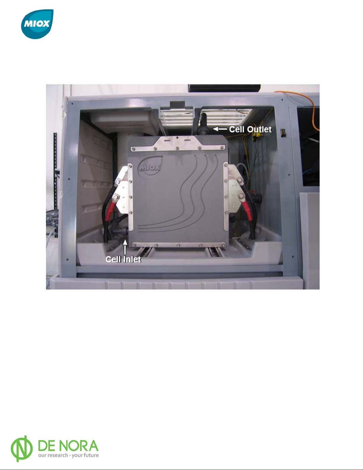
Plumbing connections to the cell depend on the number of cell modules that make up the cell
assembly. For a single module cell (M1 or H1), the plumbing inlet and outlet fittings are
installed directly to the cell (Figure 26).
Figure 26 Cell Plumbing Connectons - 1 Module
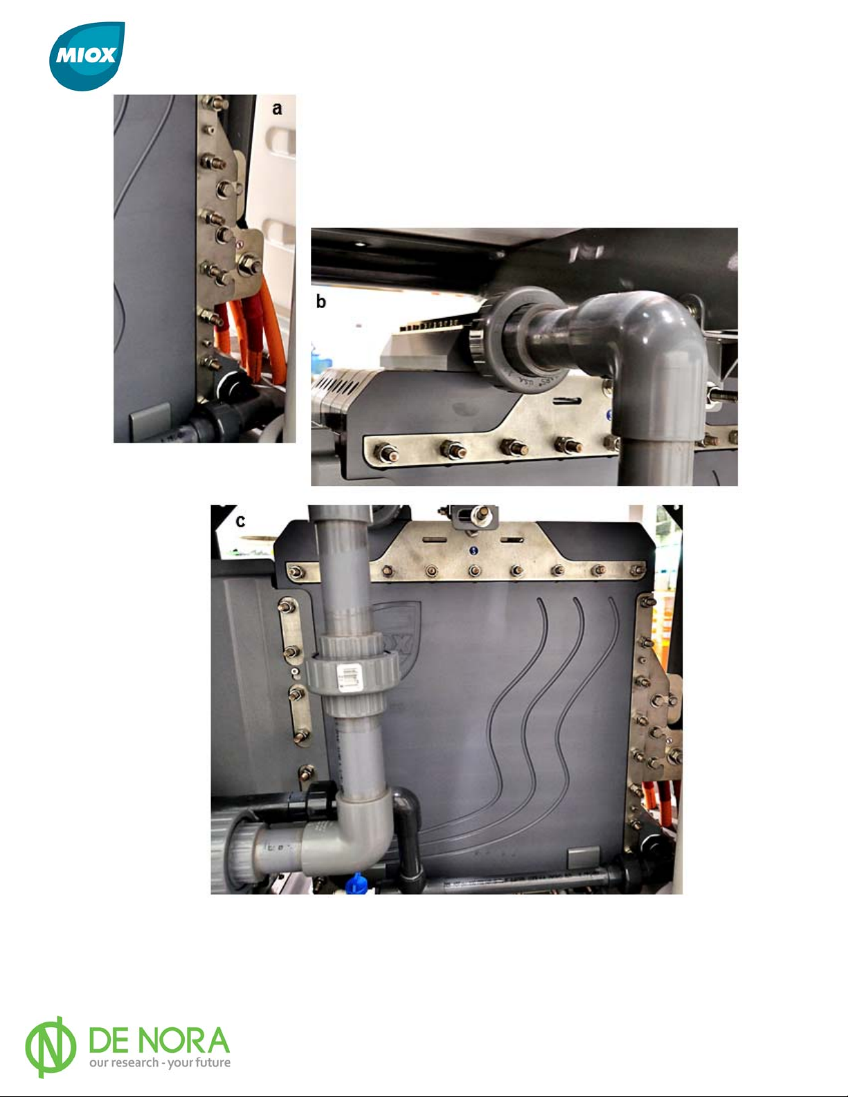
For a multiple module cell (M2-M5 or H2-H5) the plumbing inlet and outlet fittings are
installed to the cell inlet/outlet manifolds that are mounted on the cell (Figure 27).
Connecting the inlet plumbing to the cell/manifold inlet is made by mating the inlet plumbing
female union to the cell inlet male union. Connecting the outlet plumbing to the cell/manifold
outlet is made by mating the outlet plumbing female union to the cell outlet male union.
P/N: 102-00076-G Page 42
Page 44
MIOX RIO Series Operators Manual
Figure 27 Multiple Module Cell Inlet/Outlet Manifold
a) Inlet Plumbing from Rear b) Outlet Plumbing from Rear c) Outlet Plumbing Assembly
P/N: 102-00076-G Page 43
Page 45
MIOX RIO Series Operators Manual
Cell Guard Installation
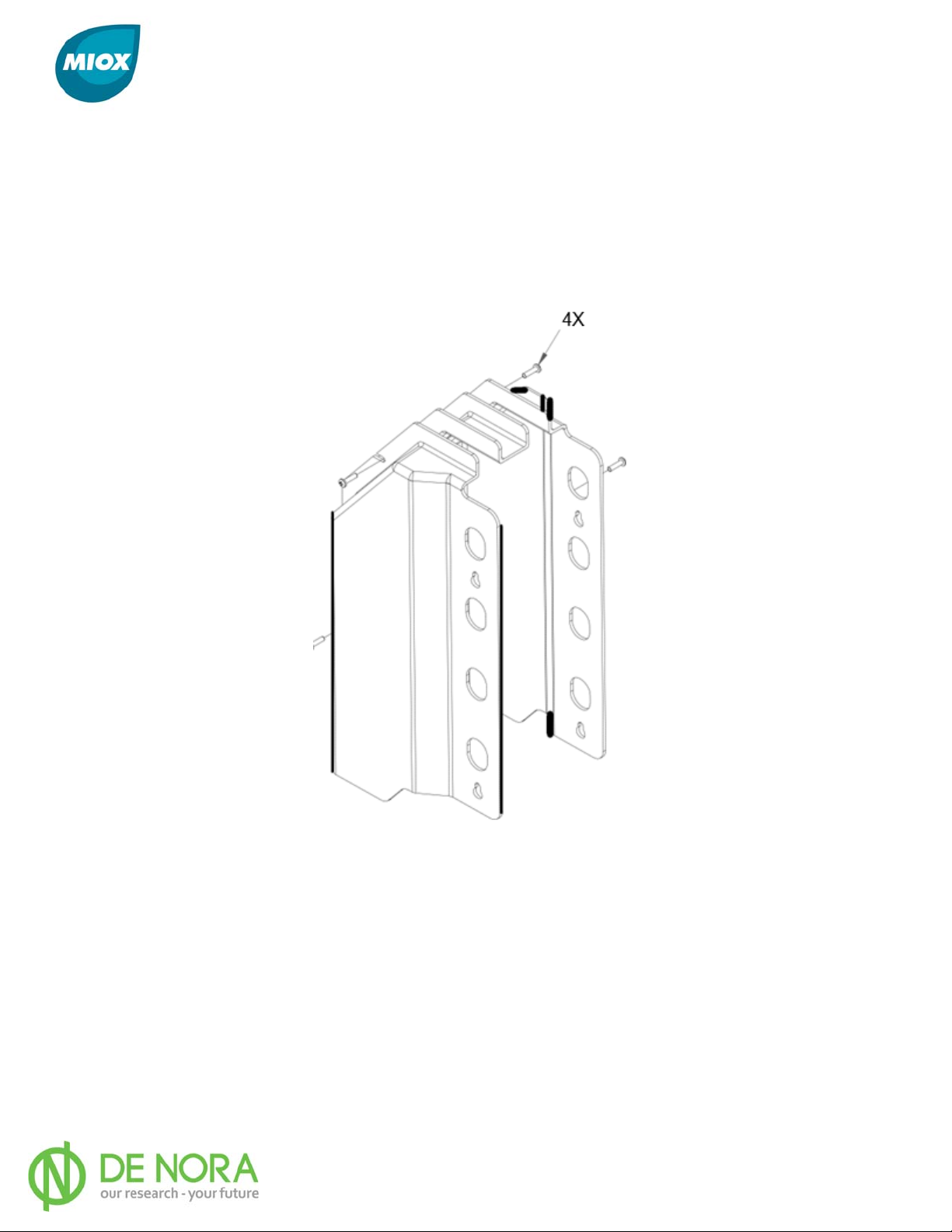
Cell guards provide protection from the cell leads. Cell guards are shipped pre-assembled, a
left side (Figure 28) and a right side. To install, disassemble the front piece of the guard
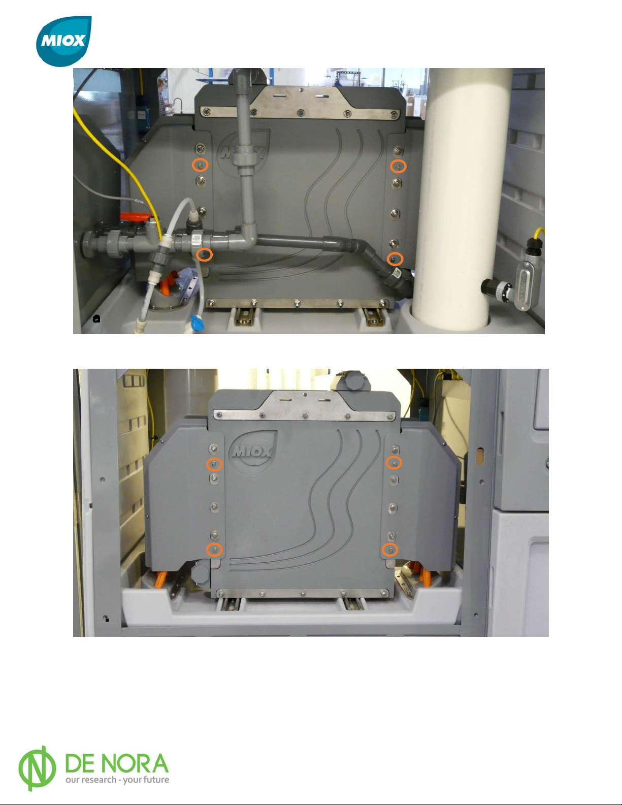
from the middle piece. Position the middle and back pieces of the guard on the cell, sliding
the slots on the guard onto the socket head shoulder screws on the cell (Figure 29). Tighten
the two screws on the guard. Position the front piece of the guard onto the cell using the
socket head shoulder screws (Figure 30). Re-assemble the front piece to the rest of the
guard. Repeat on the other side
Figure 28 Cell Guard Pre-Assembly
P/N: 102-00076-G Page 44
Page 46
MIOX RIO Series Operators Manual
Figure 29 Location of Socket Head Shoulder Screws – Back
Figure 30 Location of Socket Head Shoulder Screws - Front
P/N: 102-00076-G Page 45
Page 47
MIOX RIO Series Operators Manual
Operations
Safety Precautions
The oxidant solution is a disinfectant - NOT DRINKING WATER – and therefore
should NOT be consumed without diluting it with water. The RIO Series OSG is not a
desalinization device for making fresh water from salt water, but instead uses salt water
in making oxidant solution.
For water treatment, ensure the proper dose of oxidant for the water to be treated. Consult a
qualified engineer, MIOX distributor, or salesperson for proper dose rates.
Do not add other chemicals to the brine or oxidant tanks.
Ensure that all venting requirements are strictly followed. Refe r to MIOX ’s
White Paper .
Ensure that NO flames or ignition sources are in or around the oxidant tank.
and Warnings
Hydrogen Safety
Initial Settings and Startup Checks
Electrical Check
Verify connection to correct power source, for standard units: 480 VAC, three-phase, 50-60
hertz. For 400V units: 400 VAC, three-phase, 50-60 hertz.
Initial Salt Filling
1. Flush the water line feeding the brine generator
2. Ensure that all hose fittings are tightened
3. Close the outlet valve and open the inlet valve to fill brine generator with water only.
This will hydrostatically test the tank for leaks and wash the quartz rock.
4. Once the tank is filled, drain dirty water to waste.
5. Pour salt into brine generator until it is full. Salt can be loaded up to the 4” cap on the
brine float assembly.
6. Open the brine generator water supply valve and fill with softened water. The
generator has a float that will stop the flow of water to the brine generator. Observe
that the water flow stops at the correct level.
7. After filling the brine generator with salt and softened water, allow 60 minutes for the
salt to dissolve before priming the brine proportion pump
P/N: 102-00076-G Page 46
Page 48

MIOX RIO Series Operators Manual
Checks Prior to Startup
Prior to initial OSG start-up, the following items should be checked:
1. Hose fittings tightened
2. Electrical connections to cell electrodes good [40 ft./lbs. (54 Nꞏm)]
3. Electrical power connection good (correct wiring at disconnect switch)
4. Power and switch gear compartments securely closed
5. Water valves open
6. Brine generator drain valve in closed position
7. Brine generator full of salt and brine feed valve open
8. Oxidant tank vent properly installed
Brine Boost Operation
The brine boost system must be primed before operation. Ensure all plumbing connections are
tight. Remove a fitting or loosen a union after the brine boost pump. This allows air to escape
from the boost pump and plumbing. Once a liquid stream comes out of the fitting/union, replace
the fitting/tighten the union. The brine boost system is now ready for initial operation.
Water Softener Operation
Ensure that the water softener is operating properly before initial startup by testing the water
from the water softener for hardness. If hardness is more than 1 grain per gallon (17.1 ppm), the
softener is not functioning properly. Verify the following:
1. Water Feed Supply - the water feed supply must be connected to the proper inlet on the
water softener head, with the inward-pointing arrow. Water from the softener to the RIO
Series OSG must be connected to the outlet, with the outward pointing arrow.
2. Check Valve - the brine recharge hose has a check valve in the middle of the line with an
arrow that must be pointing from the brine generator toward the water softener.
3. Brine Generator - verify that there is sufficient brine in the brine generator for the water
softener to regenerate. Confirm that brine flows freely out of the tank.
P/N: 102-00076-G Page 47
Page 49
MIOX RIO Series Operators Manual
Routine Operations
Turn On Disconnect Switch
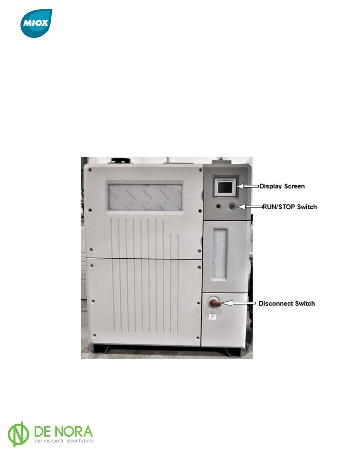
The disconnect switch is located on the outside of the switch gear compartment (Figure 31).
Once the disconnect switch is moved to the ON position, the display and OSG will power up.
Push Run/Stop Switch
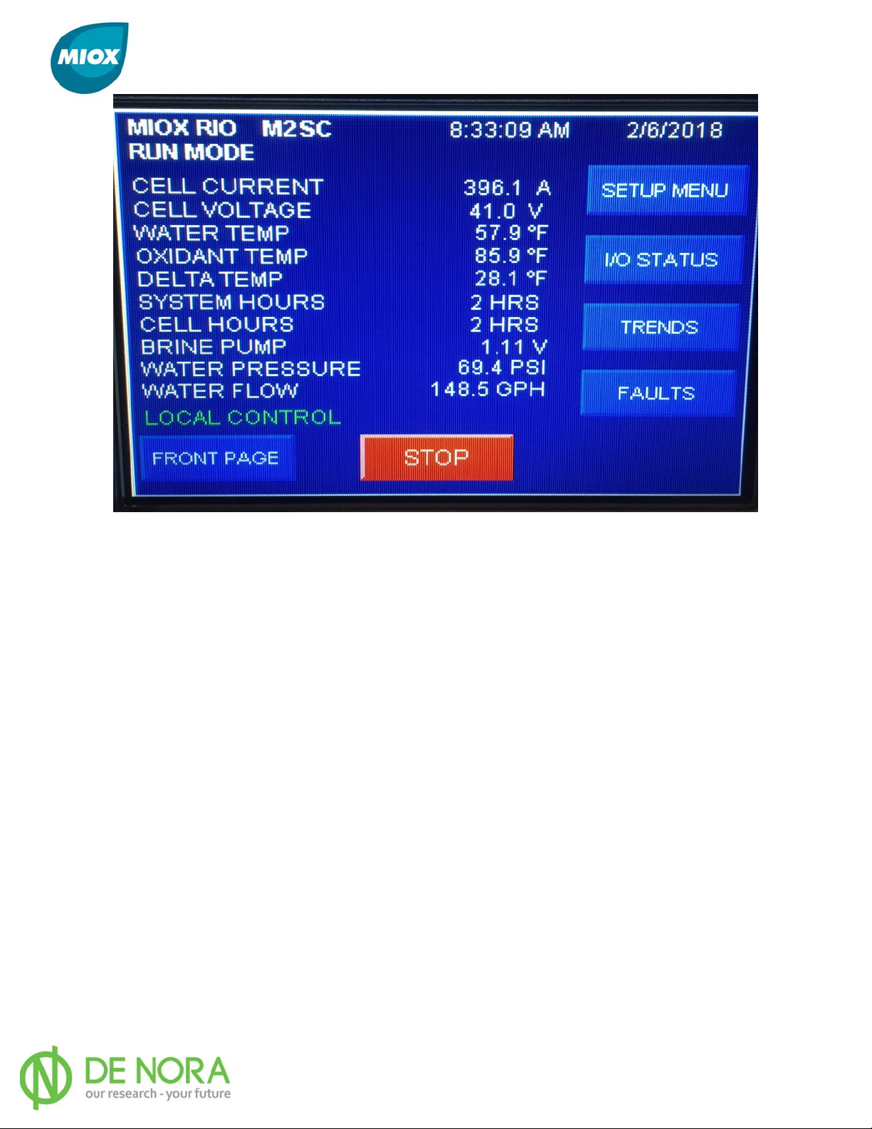
Push the RUN/STOP switch in and press the “START” button on the display screen (Figure 32)
to power up the cell. The OSG monitors the oxidant level switch. If the oxidant tank is empty,
the OSG will attempt to initiate the startup sequence and then begin to run. If the solution
tank is full, the OSG will go into standby.
Figure 31 Display Screen, Run/Stop Switch, and Disconnect Switch
P/N: 102-00076-G Page 48
Page 50
MIOX RIO Series Operators Manual
Figure 32 Main Display Screen
Startup Sequence/Operating Window
The RIO Series OSG goes through a start-up sequence that includes brine proportion pump
activation and purging the cell of warm water. When power is applied to the cell, the current
flowing through the cell is measured. During normal operation, the amperage will fluctuate
slightly. Approximate amperage for each RIO M cell module is 200 amps and for each RIO H
cell module, 225 amps. If the cell amperage is too high, the brine flow rate is reduced by
slowing the pump; conversely, too low an amperage is corrected by speeding up the pump.
The cell amperage will increase until it stabilizes in the optimal operating range, the operating
window. Cell voltage and current are indicated on the Main Display screen (Figure 32). The
brine proportion pump will also step up or down, but the pump control voltage, indicated as
Brine Pump Voltage, should be between 0 and 5 VDC.
When the operating window is reached, the electrolytic cell will begin to produce oxidants and
fill the oxidant tank. When the oxidant storage tank is filled to the high level, the level sensor
places the OSG into standby mode. When the oxidant storage tank is drained of oxidant
solution below the bottom level sensor, the OSG will automatically restart and run until the
oxidant tank is filled to the highest level.
When the OSG goes into standby mode, the OSG controller goes through a purge sequence to
remove brine from the lines and cell. Brine in the cell can cause an adverse battery effect that
can shorten the life of the cell. During the shutdown sequence, the brine proportion pump will
turn off. After 90 seconds the water solenoid valve will also turn off and the cell will power off.
P/N: 102-00076-G Page 49
Page 51
MIOX RIO Series Operators Manual
During the startup from standby mode, the OSG also goes through a startup sequence. When
the low level switch in the oxidant storage tank is activated, the solenoid opens to allow water
flow for 60 seconds. Cell power is applied, the brine proportion pump comes on, and the OSG
should come into the operating window within five minutes.
If you have excessive stops and starts, the oxidant solution will be
diluted with start-up and shutdown flushes.
Brine Boost Pump Commissioning
The brine boost pump is electrically interlocked with the OSG. Once the OSG is in Run mode,
the pump will run. Once the pump is running, the back pressure valve must be set. Adjust
the pressure to a point that allows 3-5 PSI at the OSG. This is the optimum operating
pressure. Lower pressures cause strain on the OSG brine proportion pump and higher
pressure can cause bleed through of the brine proportion pump resulting in OSG faults.
Operation Controls
Modes of Operation
The modes of operation of the OSG are: Standby, Startup/Run, Self-Cleaning, Water Cycle,
Stop, Setup, Diagnostic, and Shutdown. Normal automated operation involves entering Run
mode to fill the oxidant tank. Once the oxidant tank is full, the OSG transition to Standby
mode. When the oxidant tank reaches a low level, the OSG will transition from Standby to
Startup to Run mode.
Standby Mode
The OSG is normally in Standby when the oxidant tank is full. The OSG can also be in
Standby if a Soft Fault condition is active and the Run/Stop switch is in the Run position.
If no Soft Faults are active, the OSG automatically transitions to Startup/Run mode
when the oxidant tank is low.
Startup/Run Mode
Startup mode verifies initial OSG condition, initiates and verifies cooling system function
and external Dilution Air system (if applicable) function. If functions are operational, the
cell is charged with water, power is applied, verified, and Run mode is entered.
P/N: 102-00076-G Page 50
Page 52

MIOX RIO Series Operators Manual
In Run mode, the brine flow is adjusted to achieve and maintain a constant electrical Current
Set
Point (CSP) to the cell.
Self-Cleaning Mode
For Mixed Oxidant Solution (MOS) configurations M1-M5, the requirements to enter into a selfcleaning mode are based upon number of hours of operations since initial startup or last cleaning.
For instances when the hours of operation are reached as a self-cleaning is required, the selfcleaning mode will occur after the system transitions from standby, but prior to entering into
run mode upon completion of the self-clean. The system returns to normal run mode with a
standard start up. Self-cleaning mode is not available on Hypo (H1-H5) configurations. Refer to
Acid Wash Cell Procedure (P/N: 102-00009) for details on a manual acid wash of the cell.
Water Cycle Mode
Water Cycle mode is entered only if the Cell Power contactor fails. The water solenoid valve will
cycle on/off. This operation is to protect the cell and its plumbing from high temperatures.
Water will flow at half of target flow rate to the oxidant tank and dilution will occur. The OSG
will remain in this mode until power is reset.
Stop Mode
The operator can access Stop mode by placing the Run/Stop switch into the Stop position (push
in switch to ratchet switch out). If Stop mode is accessed from Startup/Run mode, the OSG
will shut down with a Soft Fault. To return to Startup/Run mode, return the Run/Stop switch to
the Run position.
Setup Mode
Setup mode allows the operator to designate the values of user specified parameters on the
Operator Interface (OI).
Diagnostic Mode
Diagnostic mode allows the user to individually test each system’s output. Diagnostic mode
is only accessible from the Stop position of the Run/Stop switch. Diagnostic mode is accessed
from a button on the main screen. Once in Diagnostic Mode, the operator can toggle I/O on/off.
Once the operator leaves the Diagnostic page, all I/O reset to off.
Shutdown Mode
There are two types of Shutdown modes from the Startup/Run mode:
1. Normal Shutdown - is used when the system is shutting down for a fault that causes
the OSG to shutdown normally. Normal shutdown includes a purge function to clear
brine from the cell.
P/N: 102-00076-G Page 51
Page 53
MIOX RIO Series Operators Manual
2. Quick Shutdown - is used when the OSG needs to shut down without a purge
delay. Quick shutdown occurs with Low Water Pressure (run mode), Very High
Current, Rupture Disk Failure, or Hydrogen Monitor Alarm.
3. Self-Cleaning - the requirements to enter into a Self-Cleaning mode are based
upon number of hours of operation since initial start-up or last cleaning. For
instances when the hours of operation are reached and a self-cleaning is required,
the Self Cleaning mode will occur after the system transitions from Standby, but
prior to entering into Run mode. Upon completion of the self-clean, the system
returns to normal Run mode with a standard startup.
System Status Lights
The control panel LED indicates the OSG operating status through different colors and states
(Table 10).
Table 10 LED Status Lights
LED State/Color OSG Status
OFF STANDBY
Flashing Green
START UP and RUN mode while not in operating
Solid Green RUN mode in operating window
Flashing Yellow SHUT DOWN
Solid Yellow FAULT /STOP mode
Cycles through Green/Yellow/Red Diagnostic mode
Output Testing
The control system must provide a means for the user to set and reset outputs for testing
(Table 11). Only one function can be tested at a time.
Table 11 Output Testing
Discrete Outputs Controls/Limitations
Internal Flow Control Valve (Flush)
Internal Brine Solenoid Button input on I/O toggles output on and off
External Dilution Air Fan Enable Button input on I/O toggles output on and off
External Alarm Output Button input on I/O toggles output on and off
Brine Pump Test Button input on I/O toggles output on and off
Internal Cooling Fan Enable Button input on I/O toggles output on and off
External Brine Boost Relay Enable Button input on I/O toggles output on and off
External Water Boost Relay Enable Button input on I/O toggles output on and off
Water Solenoid with Boost (Manual Purge) Button input on I/O toggles output on and off
Button input on I/O toggles output on and off
P/N: 102-00076-G Page 52
Page 54
MIOX RIO Series Operators Manual
Fault Conditions
Anything that stops the system is considered a fault. There are two types of faults: soft
and hard. With a soft fault, the system will automatically restart when the conditions
that caused it go away. A hard fault requires user intervention to reset the system.
Response of the system to any given fault will vary depending on the condition (Table
12). Certain types of hard faults will allow the system to automatically reset in an
attempt to recover the system. The system can make up to three attempts to
automatically reset before requiring user intervention. The system will consider itself
recovered when it is running at full operational current for more than 10 minutes.
Table 12 Fault Conditions
Fault Name Condition
Delta Temp Fault
Dilution Air (DA) Failure
Fault
Interlock Trip 1
Interlock Trip 2
Interlock Trip 3
Interlock Trip 4
Hardness Monitor
Fault
Temp difference between I/O
greater than 50° F or less than
-10° F
DA status signal off when DA
enable signal on.
Bottom rear interlock tripped.
Bottom front interlock tripped.
Top rear interlock tripped.
Top front interlock tripped.
Hardness monitor trips while
running.
T
Delay
(sec)
ime
45
5
2
2
2
2
0
Cell
Power
Removed
NO
YES
YES
YES
YES
YES
NO
W
ater
Off
NO
NO
NO
NO
NO
NO
NO
Auto
Retry
NO
NO
NO
NO
NO
NO
NO
Hydrogen Monitor
Fault
Flow Sensor Loss
Feed Water Flow
Rate - Low
Feed Water Flow
Rate - High
Hydrogen monitor trips while
running.
No pulses from sensor while
flow control is running.
Feed water flow rate less than
90% of target.
Feed water flow rate more than
110% target.
0
5
30
30
YES
YES
NO
NO
NO
NO
NO
NO
NO
NO
YES
NO
P/N: 102-00076-G Page 53
Page 55

MIOX RIO Series Operators Manual
Fault Name Condition
No Air Flow Fault
Rupture Disk Fail
Contact Fail to Close
Contact Fail to Open
Cell Current - Very
High
Cell Current Variation
Cell Voltage - Low
Oxidant Temp - Very
High
Brine Pump Voltage
- High
Brine Pump Voltage
- Low
Low Water
Pressure
Diode Temp Fault
Feed Water Temp Low
Feed Water Temp High
No air flow signal while fan run
command on.
Liquid detected on rupture disk
probe.
No contact status signal when
contact enable signal on.
Contact status signal on, then
contact enable signal off.
Cell current greater than 125%
of target.
20% standard RIO cell current
variation calculation.
Cell voltage less than 30 V
when contact on.
Oxidant temp greater than
150° F.
Brine pump control voltage
greater than 4.85 V.
Brine pump control voltage
0.0 V.
Water pressure below 35 psi
Diode bank temperature switch
tripped.
Feed water temperature less
than 40° F .
Inlet water temp less than 95°
F.
T
ime
Delay
(sec)
15
120
10
300
2
5
1
1
5
10
60
60
5
Cell
Power
Removed
YES
YES
NO
YES
YES
NO
NO
NO
NO
NO
YES
NO
W
NO
YES
NO
NO
NO
NO
NO
NO
NO
NO
NO
NO
NO
ater
Off
Auto
Retry
NO
NO
NO
NO
YES
NO
NO
NO
NO
NO
YES
NO
NO
P/N: 102-00076-G Page 54
Page 56

MIOX RIO Series Operators Manual
Water Flow Control Valve Reset Procedure
On occasion an anomaly in the control signal to the modulating actuator might cause the
actuator to “freeze up” and no longer respond to the 4 – 20 mA (or 0-10VDC) control signal. If
this happens, please follow these instructions to re-set the actuator:
1. Switch off the power to the actuator. This is the voltage supplied to the large DIN plug.
2. Remove the control signal DIN plug. This is the female DIN plug in the center of the 3 DIN
plugs.
3. On the male DIN plug on the actuator (the center control signal plug) make a short circuit
between pin 1 and ground. Looking at the male DIN plug, head on, pin 1 is the pin in the
3:00 o’clock position. Ground is the flat pin in the 6:00 o’clock position. The short circuit
can be made with a piece of wire, or a screwdriver blade. The short circuit must be made
when the power is switched back on, then the short circuit released while the power
remains on.
4. Turn on the power while the short circuit is made. Leave the power on and remove the
short circuit.
5. The actuator should begin to re-set itself. It will move to full open position and then back
to full closed position (for a normally closed actuator; if it is a normally open actuator, the
opposite will occur).
6. Plug in the control signal DIN plug.
7. The actuator should function properly again. If not, the problem is elsewhere. Contact
your MIOX customer support provider.
System Shutdown procedure
This sequence for shutdown of the RIO Series OSG is designed to properly flush the electrolytic
cell and help maintain the overall condition of the MIOX equipment. When turning the system
off for a prolonged period of time, it is important to follow this sequence:
1. Push in the red RUN/STOP switch.
2. Wait 30 seconds while the OSG performs a shut-down purge cycle.
3. Purge the brine proportion pump by isolating the brine generator outlet valve and
disconnecting the suction line to the brine proportion pump. Connect a water source to
the suction side of the brine proportion pump.
4. Start the OSG to flush the pump with brine-free water
5. Push in the red RUN/STOP switch to the OFF position.
6. Turn the disconnect switch to the OFF position.
7. Drain the oxidant tank(s), brine generator(s), and drain cell if freezing conditions could
exist.
8. Disconnect the power source.
P/N: 102-00076-G Page 55
Page 57
MIOX RIO Series Operators Manual
General Periodic Maintenance
The RIO Series OSG should be monitored periodically to ensure that the unit is running
properly. MIOX recommends daily, weekly, monthly, and quarterly checks. In order to
maintain a history of system performance and assist in troubleshooting and warranty work,
it is recommended that a log be kept near the OSG for easy record keeping.
Safety Precautions
Disconnect power before working on OSG.
Do not defeat or tamper with electrical interlocks or lockout mechanisms.
Proper venting of the oxidant tank is mandatory. Refer to MIOX Hydrogen Safety White
Paper
NO flames or ignition sources in or around the oxidant tank
Use confines space procedures prior to entry to the oxidant tank.
Do not add other chemicals to the oxidant tank.
Always follow the plumbing and venting procedures recommended by MIOX and your local
codes. Consult MIOX or an engineering professional prior to making changes to piping in
oxidant tanks
and Warnings
Daily Maintenance
Check the Salt Level - There must always be ample salt in the brine generator for
OSG use, as well as water softener regeneration. MIOX recommends keeping a
minimum of 1 foot (0.3 meters) of salt in the brine generator at all times.
NOTE During the first few weeks of operation, it is critical to check the MIOX
OSG more frequently to identify and solve site-specific problems, fine tune
the injection rate, and tighten any connections that may have loosened
during shipping.
P/N: 102-00076-G Page 56
Page 58

MIOX RIO Series Operators Manual
Weekly Maintenance
Check Feed Water Pressure (35 to 100 psi; 241.5 to 689 kPa) – The feed
water pressure of some water systems tends to fluctuate. If water pressure goes
below 35 psi (241.5 kPa) or above 100 psi (689 kPa), it could damage the MIOX
OSG.
Check for Leaks – Ensure that hoses and fittings are tight and leak-free. Correct
any leaks with Teflon tape. Do not use any type of Teflon paste since excess could
potentially break free and gum up the brine proportion pump or water softener. If
the cell perimeter is seeping, tighten all perimeter bolts (Table 13). Check the brine
proportion pump fittings regularly for seepage and check the connections to verify
that there is no salt around the flange sealing area.
Check for Loose Connections/Corrosion – Check cell leads and lugs for
corrosion. For light corrosion, clean cell leads and lugs with a fine sandpaper or a
wire brush. If severe corrosion is present, replace the cell lead. Torque cell lead
connections to 40 ft-lbs (54 N·m).
Check Chlorine (FAC) Production – Check and note chlorine production on the
MIOX OSG Log Sheet (Appendix D) to identify trends over time.
Table 13 Perimeter Bolt Torque Specifications
Main Bolt Torque
(± 1ft/lbs. 1.4 Nꞏm)
Check Water Softener (< 1 grain) – Test water flow from the water softener with
a hardness test kit to ensure that the softener is functioning properly. Water should
be less than 1 grain (17.1 mg/l as CaCO
M1/h1 M2/H2 M3/H3 M4/H4 M5/H5
20 ft./lbs.
(27 Nꞏm)
21 ft./lbs.
(28 Nꞏm)
) hardness.
3
22 ft./lbs.
(33 Nꞏm)
23 ft./lbs.
(35 Nꞏm)
25 ft./lbs.
(38 Nꞏm)
P/N: 102-00076-G Page 57
Page 59

MIOX RIO Series Operators Manual
Monthly Maintenance
Check Power – Verify that AC supply voltage is within 480 VAC +/-10% for
standard units. For 400V units, verify it is within 400 +/- 10%.
Toggle Day Tank Float Switch – The system is in standby when both floats are up.
At this point, manually push both floats down to verify that the system operates.
Floats should move smoothly approximately 1/2” in either direction. When both
floats are pushed down, the OSG will come out of stand-by and begin oxidant
solution production
Quarterly Maintenance
Clean Brine Tank – Using a wet rag, wipe down the interior of the brine generator
tank wall to remove any dirt or buildup.
Clean or Replace the Brine Filter and Water Filter – The brine and water filters
are the same 5-micron standard type unit for removal of particulate matter. The
brine filter and water filter are located prior to the water softener or OSG. The OSG
should be off or in standby mode when filters are removed or replaced. Visually
inspect the filter for clogging and debris. If flow is restricted, the filter should be
replaced. Reinstall the filter. Discard the old filters according to local environmental
codes.
Check Controls Wiring Connections – Electrical heating and cooling cycles may
loosen connections. After turning OSG power off, check all connections for tightness
by gently tugging on them. Tighten any loose screws or bolts. Wires should be clean,
dry, and corrosion-free.
Annual Maintenance
Drain and clean the brine generator every year to remove build-up that can be up to
several inches thick. Drain and clean the oxidant solution tank annually to remove
particulates. Avoid any ignition sources in the vicinity of the oxidant solution tank.
P/N: 102-00076-G Page 58
Page 60

MIOX RIO Series Operators Manual
Electrolytic Cell Replacement
Generally, the cell will have a production life of several thousand hours. However,
the life of the cell is affected by salt and water quality, water hardness, pH, and
alkalinity. It is essential that ≥ 99.5% pure salt is used, with concentrations of Ca ≤
0.03%, Mg ≤ 0.02%, and Mn ≤ 0.005%. If the following four conditions exist
simultaneously, a replacement cell may be required:
1. Oxidant temperature is high with normal water and brine flows
2.
High brine proportion pump voltage
3.
Chlorine production is significantly below normal level
4.
Salt consumption is increased.
Returning an Old/Damaged Cell
You may return a defective product to your original point of purchase, or the
authorized MIOX dealer or distributor from whom you purchased the product. Please
confirm the terms of its return policies prior to returning the product. Typically, you
must include product identification information, including installation site name,
system serial number and number of hours the cell has been used with a detailed
description of the problem you are experiencing. Pack the cell in original packing
materials or equivalent to prevent damage during shipping.
Please call your MIOX distributor for questions regarding service or cell replacement.
P/N: 102-00076-G Page 59
Page 61

MIOX RIO Series Operators Manual
Storage of Equipment
If the system will be off for a prolonged time period, water feed to the MIOX OSG
should be turned off at the inlet to the water softener. In addition, the brine tank,
tubes, and piping should be drained, and the brine proportion pump should be
flushed with clean water.
If the OSG is being shut down for the winter, the water softener should be protected
from freezing, either by heating the room, removing the softener to a heated
location, or draining the softener. If the OSG is completely drained, the OSG itself
does not have to be relocated. Draining includes the electrolytic cell, the brine tank,
and all piping. The brine proportion pump should be purged with fresh water before
draining. Dried salt in the brine proportion pump head can cause startup difficulties
when the unit is restarted. If compressed air is available (<50 psi (345 kPa)) blow
out all passages.
P/N: 102-00076-G Page 60
Page 62

MIOX RIO Series Operators Manual
Troubleshooting Guide
Table 14 Troubleshooting Guide
System Display Fault Cause
(most likely to least)
Very High Oxidant
Temp
High Brine Pump
Voltage
Low Brine Pump
Voltage
Cell outlet
temperature exceeds
150° F
Brine proportion pump
control voltage
exceeds maximum
value for more than 60
seconds
Brine proportion pump
control voltage below
minimum value for
more than 60 sec.
1. Low flow
2. Water solenoid
3. Oxidant
1. Loss of brine
2. Brine solenoid
3. Brine
4. Brine solenoid
5. Cell fouled with
6. Worn out cell
1. Brine propotion
2. Excessive brine
3. High Total
through cell
fuse failure
temperature
thermowell
fuse failure
fuse failure
proportion
pump fuse
failure
failure
mineral
deposits
pump fuse
failure
boost pressure
Dissolved
Solids (TDS) in
water
Remedial Action
1. Verify the
water flow is
within system
specs
2. Check fuse F10
on control
interface board
(Figure 34)
3. Check fuse F17
on control
interface board
(Figure 34)
1. Verify brine
supply to
system
2. Check fuse F9
on the control
interface board
(Figure 34)
3. Check fuse F6
on control
interface board
(Figure34)
4. Replace brine
solenoid
5. Verify water
softener is
functioning
correctly. Verify
salt meets
requirements
outlined in
Appendix B
6. Replace cell
1. Check fuse F6
on the control
interface board
(Figure 34)
2. Adjust brine
boost pressure
to between 3-5
PSI
3. Verify feed
water meets
system
specifications
P/N: 102-00076-G Page 61
Page 63

MIOX RIO Series Operators Manual
System Display Fault Cause
(most likely to least)
Remedial Action
No Air Flow
Rupture Disk Failure
Contactor Failed to
Close
Contactor Failed to
Open
Air flow switch is not
satisfied
Excessive pressure to
the electrolytic cell
Contactor did not close 1. Phase detector
Contactor did not open Contactor failed
1. Inadequate air
flow
2. Fan motor
failure
3. Fan breaker
tripped
1. Excessive
water pressure
in cell
2. Blockage in
oxidant piping
3. Rupture disk
fuse failure
tripped
2. Contactor
enable fuse
blown
3. Contactor coil
failed
1. Verify the slow
switch is
physically
moving when
fan is ON
2. Check vent
system for
obstructions
3. Reset fan
breaker
4. Contact MIOX
Customer
Service
1. Verify pressure
in cell plumbing
by observing
plumbing
compartment
pressure gauge
(<25 PSI)
2. Check for
blockage/closed
valves in cell
outlet plumbing
3. Check fuse F12
on the control
interface board
(Figure 34)
1. Check for red
light on phase
detection
device (PM1)on
switch gear
panel (Figure
33)
2. Check fuse F3
on switch gear
panel (Figure
33)
3. Check fuse F5
on control
interface board
(Figure 34)
4. Contact MIOX
Customer
Service
Contact MIOX
Customer Service.
Remove power from
unit.
P/N: 102-00076-G Page 62
Page 64

MIOX RIO Series Operators Manual
System Display Fault Cause
(most likely to least)
Very High Cell Current
Low Cell Voltage
High Cell Current
Low Water Pressure
Diode Temperature
Cell Amperage
exceeds max limit for
longer than 10 sec.
Cell voltage below
lower limit (30 VDC)
Cell amperage exceeds
limit for longer than
10 sec
Water pressure below
35 PSI
Temperature of diode
bar in transformer
compartment exceeds
max temperature
1. Low water flow
2. Water flow
3. Brine
1. Breaker
2. Contactor
3. Low AC voltage
1. Low water flow
2. Water flow
3. Brine
1. Low water
2. Water boost
1. Insufficient air
2. Excessive
3. Temperature
control valve
failure
proportion
pump
malfunctioning
tripped
failed
feeding system
control valve
failure
proportion
pump
malfunctioning
pressure
pump failure
flow to
transformer
current draw
on diode bank
switch failure
Remedial Action
1. Check fuse for
water solenoid
2. Contact MIOX
Customer
Service
1. Reset large
breaker (CB1)
in switch gear
panel (Figure
33)
2. Contact MIOX
Customer
Service
3. Verify feed
voltage meets
specification
1. Verify water
flow is within
system
specifications
2. Check fuse F10
on control
interface board
(Figure 34)
3. Contact MIOX
Customer
Service
1. Verify water
pressure meets
system
specifications
2. Verify
operation of
water boost
pumps. Check
fuse F1 on
control
interface board
(Figure 34)
1. Verify cooling
fan operation
2. Verify
operation of
current sensors
3. Replace
temperature
switch
P/N: 102-00076-G Page 63
Page 65

MIOX RIO Series Operators Manual
System Display Fault Cause
(most likely to least)
Remedial Action
Low H2O Temp
DA System Failure
Cell Current Variation
Feed water
temperature <40° F
External Dilution Air
(DA) signal in fault
condition
Large variation of
current between cell
modules and exits
1. Feed water
temperature
too low
2. Cell inlet
thermowell
failure
3. Thermowell
fuse failure
1. Dilution Air
system failure
2. External
Dilution Air
system not
used
1. Current sensor
failure
2. Cell worn out
3. Loose
connection at
cell leads
1. Check feed
water
temperature.
Contact MIOX
Customer
Service if <40°
F
2. Replace
thermowell
3. Check fuse F18
on control
interface board
(Figure 34)
1. Correct
external
Dilution Air
system failure
2. Place jumpers
across input
according to
wiring diagram
1. Determine
which sensor
failed using a
DC amp meter
2. Contact MIOX
Customer
Service to
replace cell
3. Verify leads are
tightened to
torque
specification.
See “Cell
Installation and
Removal” in
this manual for
additional info.
P/N: 102-00076-G Page 64
Page 66
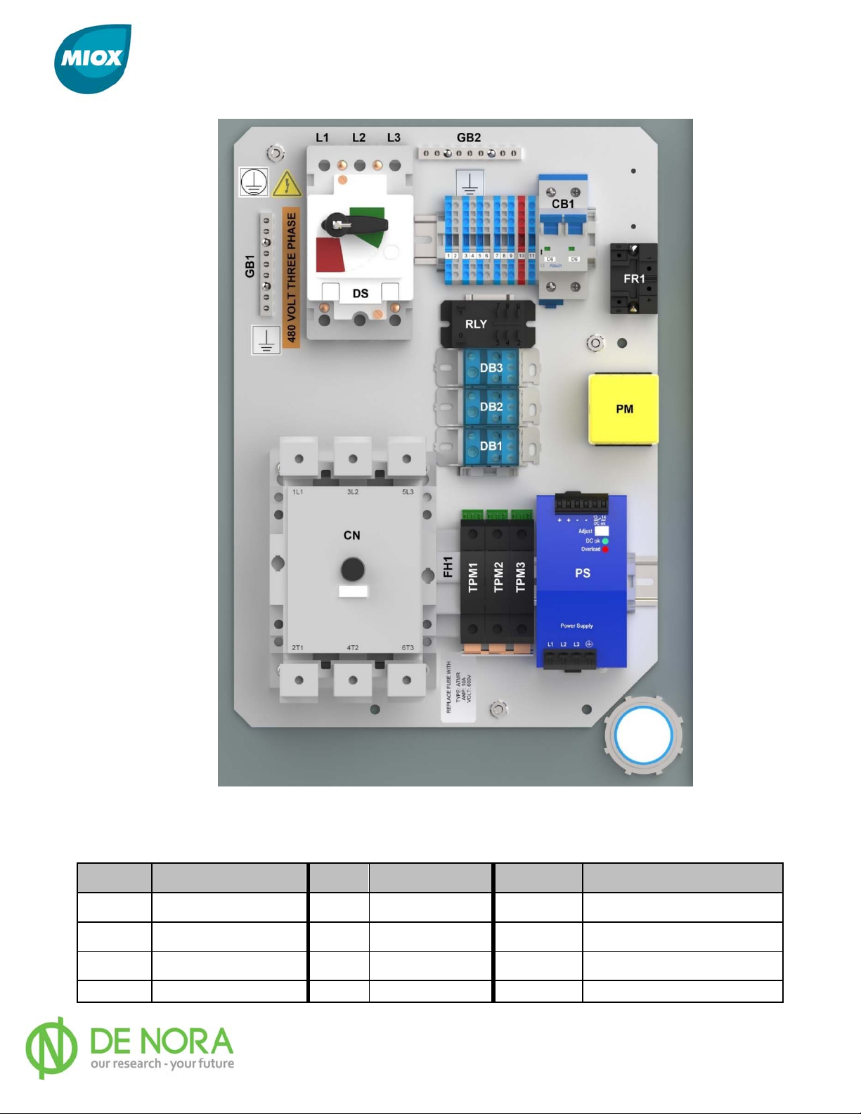
MIOX RIO Series Operators Manual
Figure 33 Switch Gear Panel Components
Table 15 Switch Gear Panel Components
Label Component Label Component Label Component
CB1 Breaker PM Power Monitor TPM 1,2,3 Transient Surge Module
DS Switch Disconnect PS Power Supply FH1 Fuse
CN Contactor RLY Safety Relay
DB 1,2,3 Distribution Block GB1, 2 Ground Block
P/N: 102-00076-G Page 65
Page 67
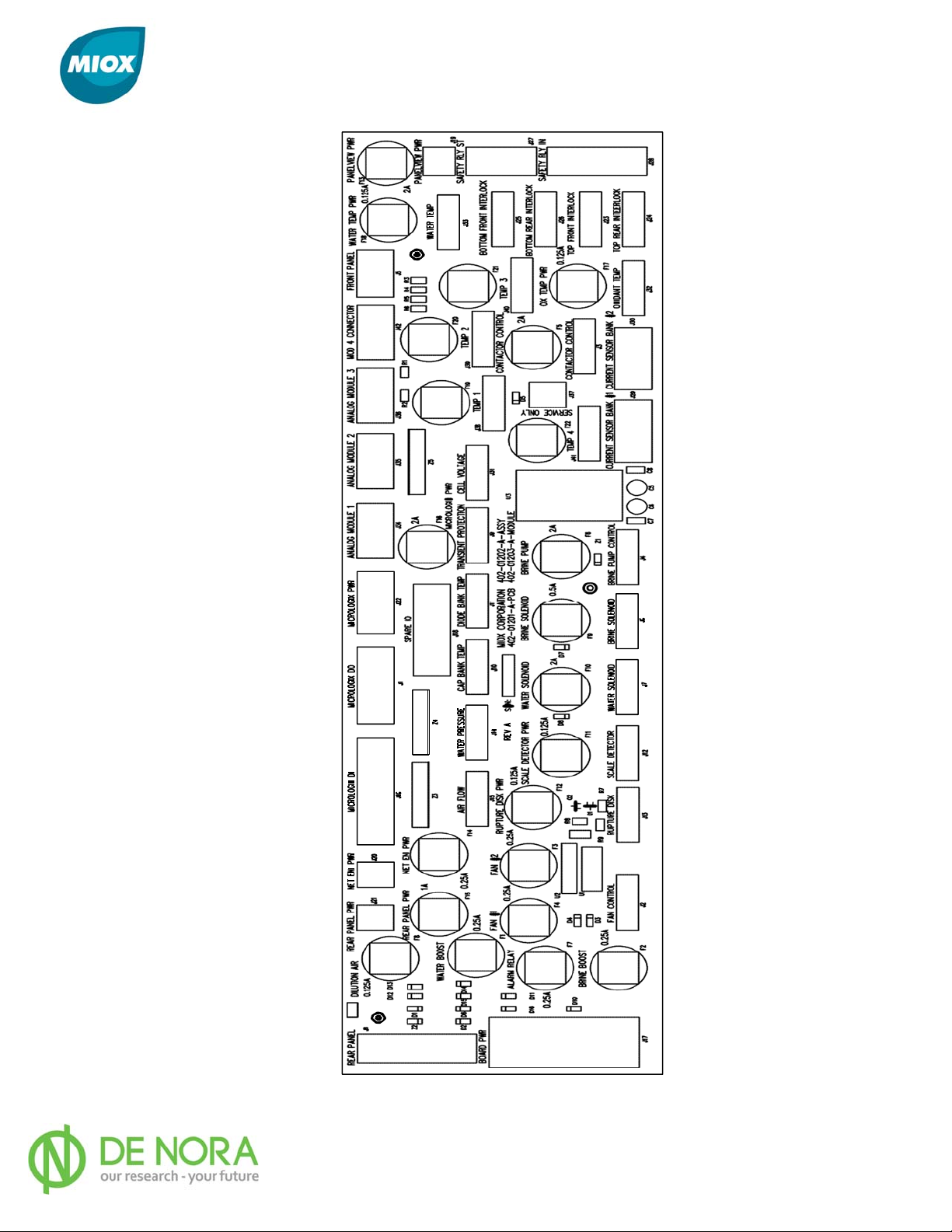
MIOX RIO Series Operators Manual
Figure 34 Interface Board
P/N: 102-00076-G Page 66
Page 68

MIOX RIO Series Operators Manual
Procedures
Brine Pump Replacement
The brine pump has been specifically designed for this application. All metal parts in contact
with brine are made of Hastelloy, which is a nickel-based alloy impervious to brine. The
pump is magnetically coupled to the motor. To avoid brine leakage into the magnetic
coupling housing, all seams are sealed.
The fluid connections to the pump are made with 3/8” diameter polypropylene tubing via
John Guest type push-in tube fittings. The fittings are 1/4” male NPT threaded connections
into the pump head. The inlet and outlet ports of the pump are identified by the flow arrow
stamped into the end of the pump head. The inlet port has a push connect swivel elbow and
the arrow head end is the outlet end.
Removing The Old Brine Pump
1. Put the system in standby by pressing the red mushroom button on the control panel.
2. Wait for the system to complete purging and go into standby status.
3. Disconnect the electrical connector by following the cable from the pump to the top of
the plumbing enclosure. While pushing the back of the cable towards the top of the
enclosure, pull the locking collar and the plug out of the receptacle.
4. Remove the 3/8” poly tube from both sides of the pump head with the push-in fitting.
The tube is removed by holding the gray collar against the body of the fitting, and
pulling the tube out of the fitting.
5. With a #2 Phillips head screwdriver, remove the 4 screws that hold the pump to the
panel in the plumbing compartment. Remove the pump.
P/N: 102-00076-G Page 67
Page 69

MIOX RIO Series Operators Manual
Installing the New Brine Pump
6. Place the pump in the plumbing enclosure, and with a #2 Phillips head screwdriver,
reinsert the 4 screws that hold the pump to the panel in the plumbing compartment.
7. Insert the 3/8” poly tube on both sides of the pump head by pushing in the tubing all
the way to prevent leakage.
8. Replace the electrical connector plug in its receptacle by pushing until it locks into
place.
9. Clean up any spilled liquid and remove the rags from the cell enclosure.
10. Restart the system.
11. As soon as the control panel display indicates that the brine pump has started, place
your hand on the pump and verify that the pump is rotating. Pump rotation will be
indicated by a slight vibration felt in the pump.
12. Verify that brine is flowing through the tubes in and out of the brine pump. It is
possible that brine may be air-locked. In case of an air-lock quickly disconnect and
reconnect the inlet tube to the pump and allow the air to purge out of the line.
13. Verify that the system reaches the operating amperage range properly.
14. Contact MIOX Customer Service for returning damaged brine pump.
Rupture Disk Maintenance
The rupture disk is designed to prevent excessive pressure build up inside the cell. If the
cell pressure exceeds 25psi then a diaphragm inside of the rupture disk union bursts. A
probe located on the post side of the union senses liquid that is discharged. The probe
notifies the system to shut down immediately. On the display, “Rupture Disk Failure” is
displayed. The liquid in the cell is discharged to drain in this event.
Replacing the Rupture Disk Diaphragm
15. Put the system in standby by pressing the red mushroom button on the control panel.
16. Remove the rear upper exterior panel to gain access to the rear cell area.
17. From the rear of the system and facing the cell a union with soft tubing will be located.
This is the rupture disk assembly.
18. Slowly unthread the union halves. Inside is the diaphragm. The diaphragm is made of
Teflon and the thickness determines the rupture pressure. If it is ruptured a hole can be
seen.
19. Remove the damaged disk and replace with a new one. Replacement disks have been
furnished with the OSG operations kit. If more are needed contact MIOX customer
service or other appropriate service representative.
20. Carefully thread the union back together with the disk centered inside.
P/N: 102-00076-G Page 68
Page 70
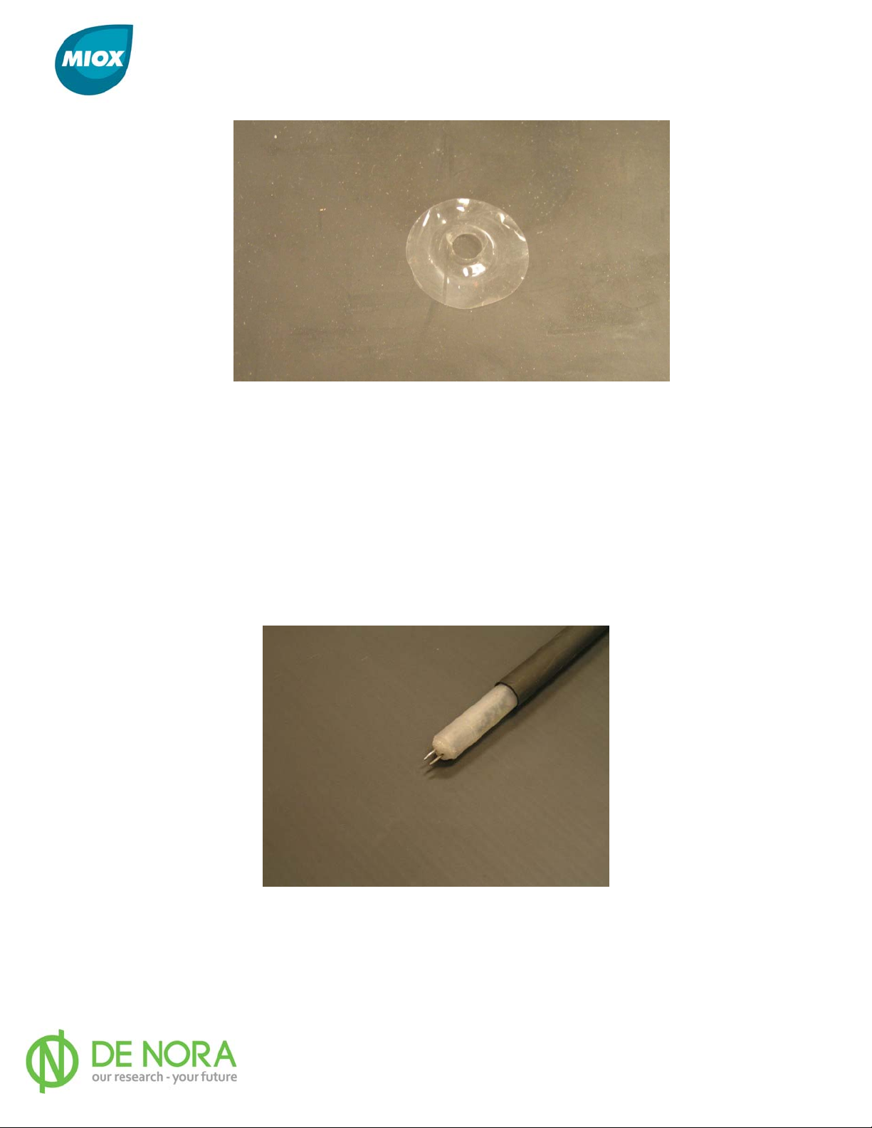
MIOX RIO Series Operators Manual
Figure 35 Rupture Disk Ruptured Diaphragm
Rupture Probe Maintenance
In the event of a rupture disk failure, the probe must be cleaned.
1. A yellow cord will be found inline post rupture disk assembly. This is the rupture probe.
1. Unplug the probe from the push-in fitting.
2. Carefully clean the two probe sensor tips with water. Rinse if possible. Do not bend the
sensor tips.
3. Before reinserting the probe make certain that the metal contacts on the tip are dry.
4. Reinsert probe into the push-in connector.
Figure 36 Rupture Probe
Acid Washing the Cell
See MIOX Acid Washing Cell Procedure (P/N: 102-00009). Contact MIOX Customer Service
if copy is not included with the Acid Wash Kit.
P/N: 102-00076-G Page 69
Page 71

MIOX RIO Series Operators Manual
Oxidant Demand Testing
The oxidant demand of water is a measure of the amount of oxidant needed to properly
disinfect water. This value is extremely important for accurately sizing and maintaining
MIOX equipment. Oxidant demand is determined by adding oxidants in several
concentrations to raw untreated (sample) water and measuring the FAC over time.
Equipment Needed
100 mL graduated cylinder
Four (4) 100 mL glass jars with lids
Pipette that can accurately measure 0.1 mL increments
Chlorine test like (i.e. DPD, Color Wheel, Colorimeter, or AccuVac)
Timer or watch
Calculator
Identify Starting Range
The initial oxidant demand test should use a 5 ppm dose to identify the correct starting
range. If a 5 ppm dose is consumed in less than 30 minutes, the demand of the water is
greater than 5 ppm, and the dose rates of 10, 15, and 20 ppm should be used for testing.
Conversely, if the 5 ppm dose is only moderately decreased in 30 minutes testing should be
performed with 1, 3, and 5 ppm doses.
Use the following formulas to determine the amount of oxidant and sample water to use
(based on 100 mL samples).
Dilution Factor (X) = Oxidant FAC / Dose
mL of oxidant = 100 / X
mL of sample water = 100 - (100 / X)
Oxidant FAC is the concentration of oxidant, which varies with each MIOX OSG model. The
output of each unit should be measured, according to the procedure for Chlorine Testing, to
determine the exact concentration of the oxidant and catholyte.
Example:
1. Determine the amount of oxidant and sample water to be used. Always start with start
with a 5 ppm dose for the first test. Suppose you are using a MIOX OSG that just
generated an oxidant solution concentration of 250 ppm. First, you must determine the
dilution factor (X):
Dilution Factor (X) = Oxidant FAC / Dose = 250 / 5 = 50
P/N: 102-00076-G Page 70
Page 72

MIOX RIO Series Operators Manual
2. Determine the volume of oxidant and sample water to be used based on X:
mL of Oxidant = 100 / X = 100 / 50 = 2 mL
mL of Sample Water = 100 - (100 / X) = 100 -(100 / 50) = 100 - 2 = 98 mL
Thus, add 2 mL of oxidants to 98 mL of sample water for the first FAC reading
3. Determine the doses for subsequent measurements.
Dilute the oxidant as determined above and after 30 minutes, take an FAC reading. If FAC is
unmeasurable, all of the oxidants have been consumed and you need doses of 10, 15, and
20 ppm for subsequent testing; otherwise if FAC has not significantly diminished, use 1, 3,
and 5 ppm doses for subsequent testing. In this case, assume that the reading was 2.5 ppm
after 30 minutes, indicating you should use test doses of 1, 3, and 5 ppm.
Setup Calculations
Use the formulas given above to determine the amount of oxidant and sample water to use
(based on 100 mL samples) for each of the doses. The sum of your oxidant and sample
water volumes should add up to 100 mL since it provides enough volume for multiple FAC
measurements at the various testing times.
Example:
Determine the oxidant and sample water volumes for the 1, 3, and 5 ppm doses. Given
that MIOX OSG is still generating an oxidant concentration of 250 ppm.
1 ppm
3ppm 5ppm
Dilution Factor (X) 250/1 = 250 250/3 = 83.3 250/5 = 50
mL of Oxidant 100/250 = 0.4 100/83.3 = 1.2 100/50 = 2
mL of Sample Water 100-0.4 = 99.6 100-1.2 = 98.8 100-2 = 98
For a 1 ppm dose, 0.4 mL of oxidant should be mixed with 99.6 mL of sample water. For a
3 ppm dose, 1.2 mL of oxidant should be mixed with 98.8 mL of sample water For a 5
ppm dose, 2.0 mL of oxidant should be mixed with 98 mL of sample water
P/N: 102-00076-G Page 71
Page 73

MIOX RIO Series Operators Manual
Procedure
Stagger preparation of each dilution by several minutes to allow enough time for accurate
analysis of FAC at each dilution. FAC readings should be taken at the following times: T = 0,
30 minutes, 60 minutes, and 90 minutes. Readings beyond 90 minutes are determined by
interpretation of data from the first 90 minutes.
• Accurately measure the volume (mL) of calculated sample water and place in a
glass jar.
• Accurately measure the volume (mL) of oxidant required.
• Add oxidant to sample water jar and swirl briefly to mix.
• Immediately measure and record the FAC concentration and time the reading is
taken (time = 0).
• Repeat the above steps for the other dilutions, measure each at time = 0 before
preparing the next dilution, and then take FAC readings at 30, 60, and 90 minutes.
Generate a table similar to the one given in the example below.
Example:
Fill out the table properly and completely. The oxidant solution must be diluted to 1 ppm, 3
ppm, and 5 ppm doses as determined in the previous example. The FAC residual is
measured in 30-minute intervals until the chart is filled out as below (measurements are
based on assumed tests for this example):
t = 0 0.4 12:00 2.1 12:05 4.0 12:10
t + 30
min.
t + 60
min.
t + 90
min.
Sample A
(1 ppm)
0.08 12:30 2.0 12:35 2.5 12:40
0.0 1:00 2.0 1:05 2.5 1:10
0.0 1:30 1.8 1:35 2.4 1:40
Time
(o’clock)
Sample B
(3 ppm)
Time
(o’Clock)
Sample C
(5 ppm)
Time
(o’Clock)
P/N: 102-00076-G Page 72
Page 74

MIOX RIO Series Operators Manual
Oxidant Demand Determination
After 90 minutes, determine which sample has the FAC residual nearest to the desired
residual specified by the water system operator. If a desired residual is unknown, look for a
FAC slightly greater than 0.2 ppm, which is usually the standard required by the state.
Subtract the selected FAC reading from the initial FAC dose for the corresponding sample.
This signifies how much of the oxidants were consumed by the water and thus how much of
an oxidant demand there is in the sample water.
Example:
Determine the oxidant demand of the water. In this case, let’s assume the operator wants a
1.0 FAC residual in the water system. Looking at the bottom row (t + 90 minutes) of the
chart filled out above, note that Sample B at 1.8 ppm is closest to the desired residual. The
initial FAC dose in this case was 3 ppm, so the oxidant demand of this water is 1.2 ppm (3.0
- 1.8 = 1.2). (This means that the operator must dose at 2.2 ppm (1.2 + 1.0 = 2.2) to
achieve his desired residual of 1.0 ppm.
P/N: 102-00076-G Page 73
Page 75

MIOX RIO Series Operators Manual
Chlorine Production Testing
Calculating chlorine production alone is the easiest way of checking the performance of a
MIOX mixed-oxidant or MIOX sodium hypochlorite system. A cell yielding a reading of 3200
ppm when it should be reading 3600 ppm may not be old and depleted -- the flows may
also be high.
Total Chlorine Production = Chlorine Concentration X Volumetric Flow per
unit time
Follow the steps below to correctly determine the total chlorine production of the system.
Equipment Needed
• 250 mL glass beaker
• 3000 mL, or 5000 mL glass jar with lid (depending on MIOX OSG being tested)
• Pipette that can accurately measure 0.5 mL or 1 mL samples
• Chlorine Test Kit (i.e. DPD, Color Wheel, Colorimeter or AccuVac)
• Chlorine Demand-Free Water (see below)
• Graduated Cylinder (1000 mL for MIOX and RIO Series mixed-oxidant or sodium
hypochlorite systems)
• Timer or a watch with a second hand
• Calculator
Preparing Chlorine Demand-Free Water
Demand-free water is required for determination of oxidant concentration in an on-site
generator. Because the oxidant is being diluted significantly, any demand in the dilution
water will cause a significant misreading in the oxidant concentration. There are two
methods for making demand-free water. The first, and preferred, method requires UV
exposure over an extended period and may not be practical for quick analysis. The second
method is quicker, but the calculations must be modified to account for the excess chlorine
residual in the water.
Note: Distilled water, whether purchased at the store or made in a lab, cannot be
trusted to be demand-free.
P/N: 102-00076-G Page 74
Page 76

MIOX RIO Series Operators Manual
Method One:
1. Add 5mL of 5.25% bleach into one gallon of distilled water.
2. Shake to mix thoroughly.
3. Allow the water to sit 2 days inside.
4. After 2 days inside, move the water outside where it will be exposed to direct
sunlight since ultraviolet light reduces chlorine to chlorides.
5. Test a sample for chlorine and allow to sit longer in direct sunlight if chlorine is
still present.
Method Two:
1. Add 3 mL of oxidant solution into one gallon of distilled water.
2. Shake to mix thoroughly.
3. Allow the water to sit for thirty minutes.
4. Check the chlorine residual in the water.
5. If there is no chlorine residual in the water, add another 3 mL, and wait another thirty
minutes.
6. If there is a chlorine residual, record the value and wait another 15 minutes.
7. Check the chlorine residual again. If the chlorine value is the same as the last reading,
the chlorine demand in the water has been met and the water is stable.
8. If the chlorine value is different than the last reading, wait 15 minutes and check it
again. Repeat this procedure until the chlorine residual is stable.
9. Record the final chlorine residual value for use in the analysis that follows.
Measuring Chlorine Concentration
1. Fill the 250 mL glass beaker with approximately 200 mL of oxidant to be tested.
2. Rinse the jar several times with chlorine demand-free water and then fill to the 2500 mL,
or 5000 mL line with demand-free water, depending on which dilution technique you are
using:
• MIOX Series Systems: Use a 1:2500 ratio (= 1.0 mL solution to 2500 mL water or
2 mL solution to 5000 mL water.)
• HYPO Series Systems: Use a 1:5000 ratio (= 1 mL solution to 5000 mL water)
P/N: 102-00076-G Page 75
Page 77

MIOX RIO Series Operators Manual
3. Rinse the pipette several times by drawing in several mL of oxidant and discarding it.
4. With the pipette, accurately measure the solution sample needed (according to the
dilution technique used above) and add to the jar containing demand-free water.
5. Cap and shake the jar several seconds to mix thoroughly.
6. Using the solution from the jar, take a reading by following the directions provided with
the test kit.
7. For demand-free water created using:
• Method One (no chlorine residual in water): For the chlorine residual value
obtained in step #6 above, multiply by the dilution ratio used in step #2.
Example: The chlorine reading from Step #6 was 1.75 mg/l, and the dilution ratio
used was 1:2500. Chlorine concentration is:
1.75 mg/L x 2500 = 4375 mg/L
• Method Two (chlorine residual present in dilution water): Subtract the chlorine
residual value obtained in step #6 above by the chlorine residual value measured in
the demand- free water to determine the net chlorine value. Next, multiply this net
chlorine value by the dilution ratio from Step #2 to get the chlorine concentration of
the oxidant.
Example: The chlorine reading from Step #6 was 2.25 mg/L, the chlorine residual
measured in the demand-free water was 0.5 mg/L, and the dilution ratio used was
1:2500. Chlorine concentration is:
2.25 mg/L – 0.5 mg/L = 1.75 mg/L net
1.75 mg/L x 2500 = 4375 mg/L
8. Repeat this process three times, take the average of these readings and assign this
value to X to calculate chlorine production.
P/N: 102-00076-G Page 76
Page 78
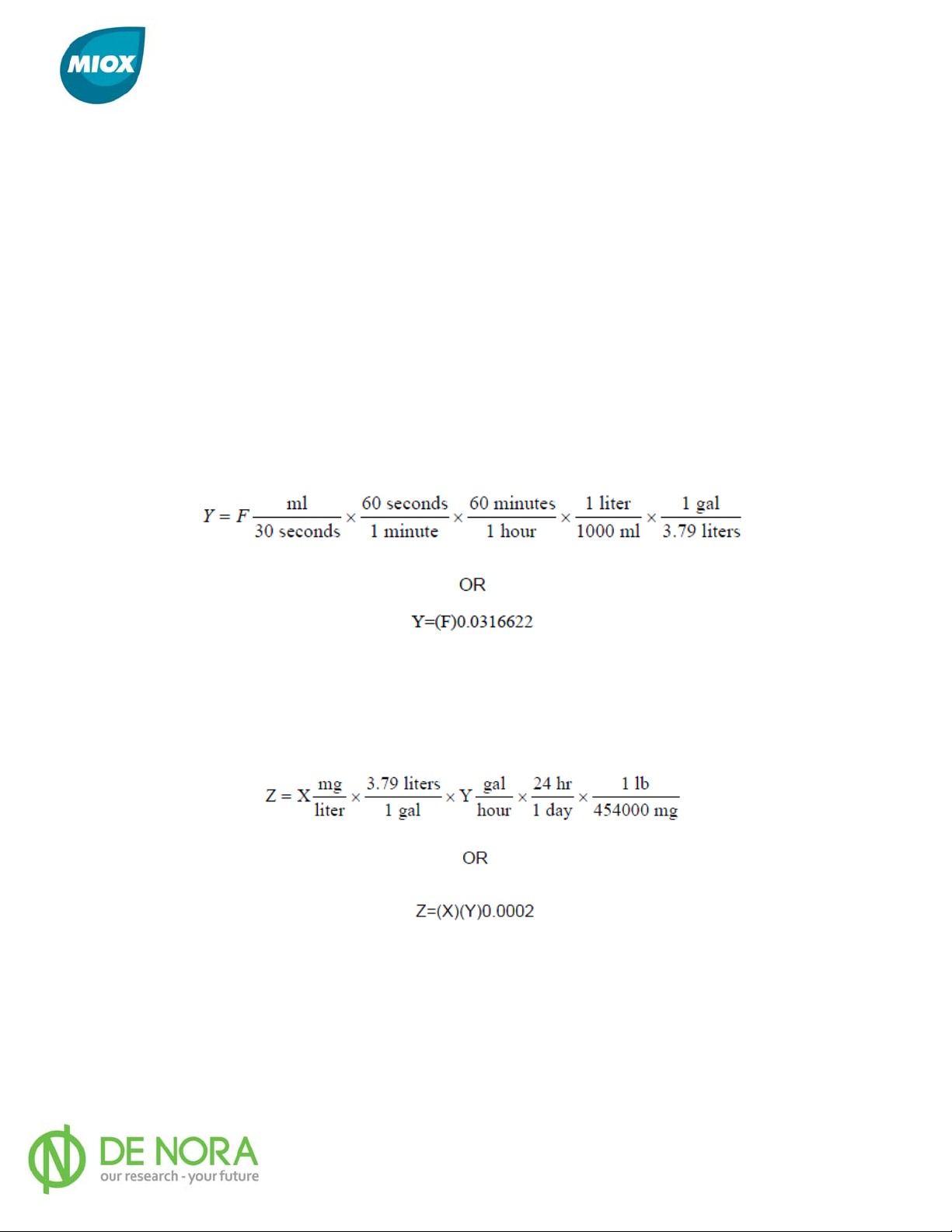
MIOX RIO Series Operators Manual
Measuring Flow
Total production of a system is the product of the concentration of the solution (determined
above) and the volumetric flow of the solution over a period of time. Low concentrations of
oxidant are often erroneously associated with low production. In order to calculate the total
production for the system, the flow rate must also be determined and adjusted if necessary.
1. Remove the tubing that feeds the oxidant tank and insert into the graduated cylinder for
exactly 30 seconds.
2. Record the number of milliliters (mL) collected in the 30 second time period.
3. Assign the number recorded in step 2 to F in the equation below to determine the flow of
solution (Y) in GPH:
Calculating Total Chlorine Production
Chlorine production is a function of concentration and flow. To calculate daily chlorine
production (Z) in lbs./day:
Where the sample solution variables are:
X = mg/L chlorine concentration
Y = gph flow
P/N: 102-00076-G Page 77
Page 79

MIOX RIO Series Operators Manual
APPENDICES
A. Water Quality Guidelines
B. Salt Quality Guidelines
P/N: 102-00076-G Page 78
Page 80
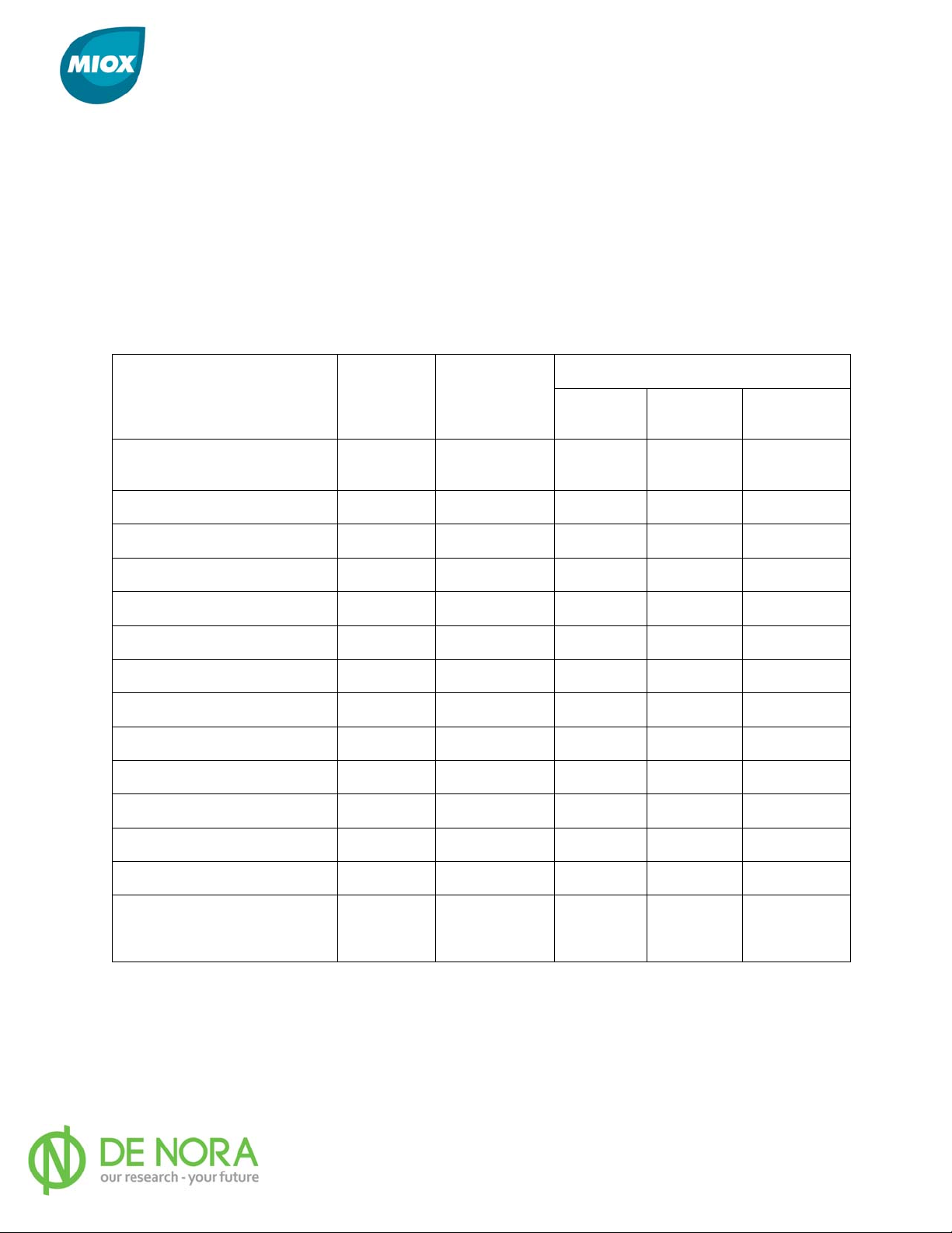
MIOX RIO Series Operators Manual
Appendix A - Water Quality Guidelines
Knowing what to look for when sizing a system will help remove hidden surprises after
installation. Most of the items on the following list will be below the limits but should be
checked nonetheless. Concentrations or measurements in brine feed water and/or treated
water that are less than the stated limits are not anticipated to have the stated effect.
These factors can affect the oxidant demand of each individual water system, the oxidant
production of the MIOX system, or the life of the cell itself. It is important to use “worst
case” measures since water quality can vary from season to season.
WHAT IS IMPACTED
MEASURE LIMIT
Oxidant
Demand
Chlorine
Production
Cell Life
Total Hardness **
Iron (Fe) **† mg/L <1 mg/L ** • •
Manganese (Mn) µg/L <50 µg/L ** • • •
Fluoride (Fl) mg/L <1 mg/L •
Silica (SiO2) mg/L <20 mg/L • •
Bromide mg/L <50 mg/L •
Cyanide mg/L <1 mg/L •
Lead (Pb) mg/L <2 mg/L •
Dissolved Sulfides (as H2S) mg/L *** •
Ammonia Nitrogen (NH3-N) mg/L *** •
Organic Nitrogen (Org-N) mg/L *** •
Total Organic Carbon (TOC) mg/L *** •
pH - 5-9 • •
grains/gal
(or mg/L)
<1 grain
(<17.1 mg/L)
• •
55-80 °F
Water Temperature Range ^ °F (or °C)
(12-27°C)
• •
**Caution: water softeners will remove these components up to a limit. See references to
maximum ferrous iron and manganese in water softener documentation. Total hardness
affects cell life only in that higher hardness requires acid washing to remove carbonate
deposits from the cell. Use of water softened to < 1 grain hardness should not require acid
washing of the cell.
*** Oxidant demand is affected by any level of H2S, ammonia or organic nitrogen, or TOC.
P/N: 102-00076-G Page 79
Page 81

MIOX RIO Series Operators Manual
† Iron may deposit Fe(OH)3 on the anode, causing an electrical “blind”, which would
increase the brine proportion pump signal voltage (brine proportion pump speed) needed for
the system to reach the operating window. Chlorine production would remain the same, but
salt conversion efficiency will decrease. The same effect is true of silica on the cathode.
^ The system will operate with water temperatures outside this range; however, there will
be a performance change. Follow the system specifications for absolute limits.
P/N: 102-00076-G Page 80
Page 82
MIOX RIO Series Operators Manual
Appendix B – Salt Quality Guidelines
MIOX requires that all Self Cleaning RIO Systems use a granular salt that meets or exceeds
the purity percentages listed below. For additional information consult the MIOX Salt
Guidelines white paper (P/N: 106-00008).
Note: Failure to use salt that does not meet these specification VOIDS the Cell
Warranty.
Component Percent
NaCl (dry) 99.5
Impurity Percent
Calcium (in all forms) 0.01
Magnesium (in all 0.01
Manganese 0.00002
Iron (as Fe) 0.0005
Insolubles 0.005
Additives 0.0001
P/N: 102-00076-G Page 81
 Loading...