

Page 1

Parts and Instruction Manual
TRS 14
Total Recovery System
Page 2

This manual is furnished with each new MINUTEMAN TRS 14 . This provides the necessary operating
and preventive maintenance instructions. Operators must read and understand this manual before operating or servicing this machine.
This machine was designed to give you excellent performance and efficiency. For best results and
minimal cost, please follow the general guidelines below:
· Operate the machine with reasonable care.
· Follow the manufacturers suggested maintenance instructions as provided in this booklet.
· Use original Minuteman supplied parts.
TECHNICAL SPECIFICATIONS
Model TRS 14
Model No.
Vac Motor
W ater Lift
Capacity
Flow
Wheels
Casters
Length
Width
Height
TRS14115
3 Stage 1 HP
80” (203cm)
14 gal. (53L)
250psi at nozzle, 1gpm
12” (30.5cm)
5” (13cm)
32” (81cm)
43” (109cm)
25” (63.5cm)
Page 3

Safety Precautions.......................................................................................................1
Grounding Instructions ...............................................................................................1
Safety Labels................................................................................................................ 2
Machine Components.................................................................................................. 2
Tools & Accessories .................................................................................................... 5
Machine Set Up ............................................................................................................ 6
Pre-Operation............................................................................................................6
Set Up .......................................................................................................................6
Operation...................................................................................................................6
Priming ......................................................................................................................6
Draining Recovery Tank .............................................................................................. 7
Machine Maintenance ..................................................................................................7
Daily Maintenance.....................................................................................................7
Weekly Maintenance .................................................................................................7
Storing Machine ........................................................................................................... 8
Troubleshooting ........................................................................................................... 8
Exploded Views..........................................................................................................10
TRS 14 - Base Assembly ........................................................................................10
TRS 14 - Solution Tank Assembly ........................................................................... 11
TRS 14 - Recovery Tank Assembly.........................................................................12
TRS 14 - Bill of Material ..........................................................................................13
Minuteman International Made Simple Commercial Limited Warranty................. 14
Contents
Page 4
Safety Precautions
This machine is intended for commercial use. Use only
recommended cleaning solutions and
accessory tools.
All operators must read, understand and practice the
following safety precautions.
The following safety alerts symbols are used
throughout this manual as indicated in their
description:
WARNING: To warn of hazards or unsafe
practices which could result in severe personal
injury or death.
FOR SAFETY: To identify actions which must be
followed for safe operation of equipment.
The following information signal potentially
dangerous conditions to the operator or equipment:
FOR SAFETY:
1. Do not operate machine:
2. Before operating machine:
3. When using machine:
-Unless trained and authorized.
-Unless operator manual has been read
and understood.
-In flammable or explosive areas.
-Unless cord is properly grounded.
-With damaged cord or plug.
-If not in proper operating condition.
-In outdoor areas.
-In standing water.
-With the use of an extension cord.
-Make sure all safety devices are in
place and operate properly.
-Do not run machine over cord.
-Do not pull machine by plug or cord.
-Do not pull cord around sharp edges or
corners
-Do not unplug by pulling on cord.
-Do not stretch cord.
-Do not handle plug with wet hands.
-Keep cord away from heated surfaces.
-Report machine damage or faulty
operation immediately to your
distributor.
-Follow mixing and handling
instructions on chemical containers.
4. Before leaving or servicing machine:
-Turn off machine.
-Unplug cord from wall outlet.
5. When servicing machine:
-Unplug cord from wall outlet.
-Avoid moving parts.
-Do not wear loose jackets, shirts, or
sleeves.
-Use manufacturer supplied or
approved replacement parts.
WARNING: Hazardous Voltage. Shock or
electrocution can result. Always unplug machine
before servicing.
WARNING: Flammable materials can
cause an explosion or fire. Do not use flammable
materials in tank(s).
WARNING: Flammable materials or
reactive metals can cause an explosion or fire.
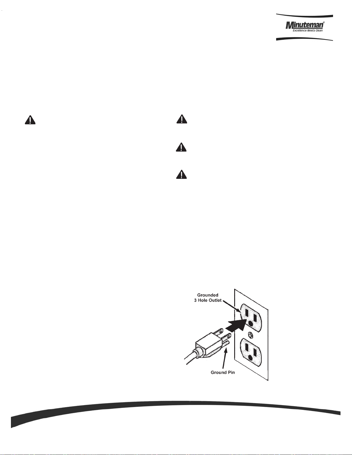
Grounding Instructions
Machine must be grounded. This
machine is equipped with a cord having an
equipment-grounding conductor and grounding
plug. The plug must be plugged into an
appropriate outlet that is properly installed in
accordance with all local code and ordinances.
Do not remove ground pin; if missing, replace
plug before use.
Parts an d Instruction Manual
Page 1
Page 5

Safety Labels
The safety labels appear on the machine in various locations. Replace labels if they become damaged
or cannot be read.
WARNING: Flammable materials can cause an explosion or fire. Do not use flammable
materials in tank(s). Flammable materials or reactive metals can cause
explosion or fire.
WARNING LABEL- Located on back. Label warns operator of safe practices of equipment
Machine Components
A
A RECOVERY TANK
B
C
D
B VACUUM HOSE CONNECTOR
C SOLUTION HOSE CONNECTOR
D SOLUTION T ANK
E MOTOR HOUSING/BASE
F PRIME VALVE
G PRESSURE REGULATOR
H PESSURE GAUGE
I PUMP SWITCH
J VACUUM SWITCH
E
Parts an d Instruction Manual
G
I
F
J
H
B
C
Page 2
Page 6

Machine Components
A
C
The unit is equipped
with 4 wire brackets
two small and two large
B
A RIGHT HAND LARGE BRACKET
B LEFT HAND LARGE BRACKET
C RIGHT HAND SMALL BRACKET
D LEFT HAND SMALL BRACKET
E RECOVERY HOSE
F CHEMICAL PROPORTIONING TANK
G BLOWER HOSE
D
H PRESSURE GUN
D
E
B
F
Left hand side large
bracket will hold the
recovery hose. Small
bracket holds chemical
proportioning tank.
A
C
G
H
Right hand side large
bracket will hold the blower
hose. Right hand side small
bracket will hold the
pressure gun.
Parts an d Instruction Manual
Page 3
Page 7

Blower Attachment
Dryer assembly
The TRS 14 comes with a blower attachment.
This attachment hooks to the blower hose and
is designed to be used as a dryer. This works
by utilizing the vacuum motor exhaust at the rear
of the machine.
Blower Hose
Vacuum Motor Exhaust
Clam Shell Design
Disconnect the two latches in the back of the unit
and rotate the top half of the machine forward
then disconnect the vac hose. This will allow
access to all motors and electronics. This
machine is very easy to service.
Parts an d Instruction Manual
Page 4
Page 8

Tools & Accessories
121092 - TRS 14 Tool Assembly Complete
121089 - 1-1/2” Curved Telescopic Wand
121086 - 1-1/2” Gulper Tool
121090 - Scrub & Vac Tool
121091 - 1-1/2” Vac Hose Assy 25 FT.
121082 - Faucet Fill Hose Assy
121101 - Blower Attachment
121097 - Slimline Injection Sprayer
Parts an d Instruction Manual
Page 5
Page 9

Machine Set Up
Pre-Operation
1. Vacuum and remove all debris.
2. Perform MACHINE SETUP procedures.
3. Inspect power cord for damage.
Set Up
1. Carefully check carton for signs of damage.
Report damage at once to freight carrier.
The machine is shipped fully assembled
and is ready for use.
2. Open lid of solution tank. Fill solution tank
with water or approved cleaning agent.
WARNING: Flammable materials can
cause an explosion or fire. Do not use flammable
solutions or materials in tank(s).
FOR SAFETY: When using machine, follow
mixing and handling instructions on chemical
containers.
Operation
1. Turn pump switch to “Hi Pressure” setting.
2. Step lightly on Power Prime for 30 seconds to prime
pump completely. Use regulator adjustment to set pump
at desired pressure on gauge.
3. Hook up your auto fill and pump out hoses to the
appropriate connections on the back of the machine.
4. Switch on Pump-Out pump. NOTE: Pump will not begin
to operate until tank is partially filled. The pump out is
controlled by a sensor in the tank. MAKE SURE YOUR
PUMP OUT HOSE IS SECURED TO A DRAIN.
5. Attach Auto Fill hose to a water inlet, such as a sink or a
garden hose. Turn on the water at medium to medium
low pressure. Monitor solution tank as it fills for the first
time, to ensure that the Auto Fill shuts off correctly.
ATTENTION: If using powdered cleaning
chemicals, mix prior to adding.
3. Attach solution hose. (Located front of
machine.)
NOTE: Make sure the quick
disconnects snap together firmly. As
you do this, always inspect hoses for
cracks or fraying. Do not use if hoses
are damaged.
4. Attach other end of solution hose to wand.
5. Attach vacuum hose to recovery tank.
6. Locate a 20 Amp dedicated power circuit, and
plug the machine cord in. The outlets must
be properly grounded. Plugging into an
ungrounded or improper outlet can result in
equipment damage, fire, and/or harm to the
operator. NEVER DISABLE THE
GROUND PIN, AS SERIOUS PROBLEMS CAN
RESULT!
6. Switch on both Vacuum 1 and Vacuum 2
7. Begin cleaning. As you clean, monitor your tank levels.
The clean water tank should never be run empty, and the
dirty water tank should never be run full.
Priming
To prime the TRS simply connect all the solution hoses
i.e. chemical metering, spray gun. Then turn on the pump
switch and push down on the priming lever. At this point
the TRS will reach its operating pressure.
FOR SAFETY: Do not operate machine unless
cord is properly grounded.
FOR SAFETY: Do not operate machine with
the use of an extension cord.
Parts an d Instruction Manual
Page 6
Page 10

WARNING: Flammable materials or
reactive metals can cause an explosion or fire.
Do not pick up.
1. Work away from outlet and power cord to
prevent cord damage.
2. Use a recommended foam control solution in
the recovery tank to prevent vacuum motor
damage. Periodically check for excessive foam
buildup in solution tank.
3. To clean heavily soiled areas, repeat cleaning
path from different direction.
4. When ball float shuts off vacuum, it is time to
empty the dirty water from the recovery tank,
and refill solution tank.
NOTE: When cleaning upholstery, always
check cleaning instructions sewn in furniture
by manufacturer
5. After cleaning, relieve water pressure from tool
before disconnecting hose. Squeeze trigger for
five seconds after turning main power switch off.
Draining Recovery Tank
FOR SAFETY: When servicing
machine, unplug cord from wall outlet.
1. Turn machine off and unplug power
cord.
2. Remove solution & vacuum hose
3. Lift up drain valve lever to empty
solution tank.
Machine Maintenance
To keep machine in good working condition, simply
follow machine’s daily and weekly maintenance
procedures.
FOR SAFETY: When servicing machine, unplug
cord from wall outlet.
Parts-Washing Solutions:
Water-Based (Aqueous) Biodegradable Solutions—
These alkaline solutions wash away both organic soils
(including grease, oil, and soft carbon) and inorganic soils
(such as epoxy , hard-water residue, corrosion, oxides, paint,
plating salts, and rust). For faster cleaning action, heat
cleaners up to 140° F. Rinse with water. Dilute general
purpose formula with four to nine parts of water . Nonferrous
metals formula is formulated for aluminum and other
nonferrous metals. Mix three to eight ounces of this powder
per gallon of water.
Maintenance
DAILY:
1. Empty and rinse out recovery tank thoroughly.
2. Wipe off power cord and check for damage, replace if
necessary. Coil cord neatly after use.
3. Clean machine with an all purpose cleaner and damp
cloth.
Weekly Maintenance
(EVERY 20 HOURS OF OPERATION)
1. Flush solution system with a system maintainer to
dissolve normal chemical buildup.
a. Pour 7.5L (2 gal) of hot water 60°C (140°F)
into solution tank. Add system maintainer
according to mixing instructions on bottle
FOR SAFETY: When using machine,
follow mixing and handling instructions on
chemical containers.
b. Operate machine for one minute.
c. Shut off machine and allow
remaining solution to break down
chemical buildup overnight.
d. Next day, spray out remaining
solution and flush system with
11L (3gal) of clean water.
2. Inspect vacuum hoses for holes and loose cuffs.
3. Inspect spray pattern for clogging. If clogged,
remove spray tips and soak them in a
recommended liquid neutralizer for up to six
hours. To remove spray tip, twist spray tip body
counter-clockwise. Do not use pointed objects to
unplug tips, damage will occur.
4. Lubricate wheels with water resistant oil.
5. Inspect machine for water leaks and loose
hardware.
6. Remove float shut-off screen from recovery
tank and clean.
Parts an d Instruction Manual
Page 7
Page 11

Storing Machine
1. Before storing machine, be certain to completely drain
and
rinse tanks of all water and solution.
2. Drain and dry the vacuum hose as well, using the drain
hose provided
3. Store machine in a dry area in the upright position.
4. Open recovery tank cover to promote air circulation
Troubleshooting
SYMPTOM: UNIT WILL NOT TURN ON:
PROBLEM: Not plugged in.
SOLUTION: Plug machine in proper outlet.
PROBLEM: Circuit breaker has popped.
SOLUTION: Reset circuit breaker. Make sure no other items are running on the same circuit as
machine. Outlet must be a 15-amp circuit.
PROBLEM: Wire from power cord has become disconnected from terminal block.
SOLUTION: Reattach wire to terminal block.
SYMPTOM: PUMP IS NOT RUNNING PROPERLY:
PROBLEM: Quick disconnects are not completely locked together.
SOLUTION: Snap quick disconnects firmly together.
PROBLEM: The solution tank is empty.
SOLUTION: Fill the solution tank up with a premixed detergent.
PROBLEM: Jet on tool is clogged.
SOLUTION: Clean jet with soft wire brush or remove jet and flush clean.
PROBLEM: Filters are clogged.
SOLUTION: Remove filters and rinse clean with water.
PROBLEM: Brass check valve is stuck.
SOLUTION: Replace with new check valve.
PROBLEM: Pump wire has become disconnected.
SOLUTION: Reconnect wire.
PROBLEM: Switch on switch plate is bad.
SOLUTION: Replace switch.
PROBLEM: Pump motor brushes are worn out.
SOLUTION: Replace pump.
Parts an d Instruction Manual
Page 8
Page 12

SYMPTOM: VACUUM MOTOR IS NOT WORKING PROPERLY:
PROBLEM: Hose not connected tightly to upholstery tool or machine.
SOLUTION: Connect hose tightly.
PROBLEM: Drain valve is not shut completely.
SOLUTION: Close drain valve completely.
PROBLEM: Vacuum tank lid is not on tightly.
SOLUTION: Secure the vacuum tank tightly.
PROBLEM: Ball float is shut off.
SOLUTION: Empty the vacuum tank of all wastewater.
PROBLEM: Water is coming out of vacuum motor.
SOLUTION: Use a low foaming detergent.
PROBLEM: Floor wand is clogged with hair, carpet fibers and or debris.
SOLUTION: Clean floor wand.
PROBLEM: Ball float is not installed correctly.
SOLUTION: Make sure that ball float is firmly installed on the elbow.
Parts an d Instruction Manual
Page 9
Page 13

Exploded Views
TRS 14 - Base Assembly
Parts an d Instruction Manual
Page 10
Page 14

TRS 14 - Solution T ank Assembly
Parts an d Instruction Manual
Page 11
Page 15

TRS 14 - Recovery T ank Assembly
Parts an d Instruction Manual
Page 12
Page 16

TRS 14 - Bill of Material
Bill Of Material - TRS 14
1 12120 3 8 s c rew, #10 x 5/8" hex he ad, zi nc 50 12 1017 1 elbo w, brass , 90 de g, 1/ 2" barb x 3 / 8" m pt
2 12106 1 2 guard, c o oli ng fan, wire 51 12 1016 1 adap t er, b ras s, 1/2 " barb x 3/ 8" fs w, bal l end
3 12112 3 2 handle , breez e 52 12 1190 1 s ol hos e , 1/ 2" kuri 100 ps i
4 12118 2 12 bolt , 1/ 4-2 0 x 1/ 2" serrat ed h ex flan ge, zi nc 53 12 1104 1 filte r, c up, i n-lin e
5 12120 4 1 plat e, wan d m o unt 54 12 1212 1 s ol hos e , 1/ 2" kuri 100 ps i
6 12115 4 5 bolt , 1/ 4-20 x 1/ 2" h ex h ead, z i nc 55 12 1041 6 washer, bun a 1-1/ 8" o d x 3/ 16" i d
7 12117 5 12 bolt , 1/ 4-2 0 x 1" hex head, s/ s 56 12 1158 8 washer, 1/ 4" i d x 1 " od, flat, s/ s
8 12112 8 2 c ast er, 4" 57 12 1127 2 hang er, w ire for inject ion b ot t le
9 12115 7 20 washe r, 1/4 " flat , s / s 58 12 1161 2 nut , he x , 1/ 4-20 s/ s
10 12116 2 16 nut, lock, 1/4 -20, ny l on in s e rt 59 12 1160 4 washer, 1/ 4" l oc k, s / s
11 12116 7 4 was he r, axle, cut 1 / 2" id 60 12 1155 2 bolt , 1 / 4-20 x 1 -1/4 " h ex hea d
12 12105 9 2 wheel , 12 " 61 12 1004 1 qd, brass, 1/4" f
13 12111 6 1 ax l e, 1/ 2 " x 21 " , B reeze, M -s eri es 62 12101 0 2 adapt er, b rass, ex tend er, 1/4" m pt x 1/ 4" fpt, h ex
14 12105 2 2 c ap, ax l e, 1/2" 6 3 121122 1 plate , m o unti ng, Q D
15 12103 7 1 gas ket , i nle t , 1. 80" i . d. 64 12 1103 1 s ol hos e , 45 " x 1/ 4" , (OAL), m x m, for S ing le Jet wa nds
16 12105 6 1 fitt ing, i nle t , pvc, 1-1/ 2 ", g ray 65 12 1206 1 s ol ta nk , m s e ries
17 12116 9 8 nut, kep, #10-32 zinc 66 12 1012 1 filte r, s t raine r, 1/ 2"
18 12116 5 27 sc re w, 10-32 x 1/ 2 phi l pan 67 12 1173 2 washer, 11/ 16"id x 1-1/ 2" od x . 075, s/ s
19 12112 4 2 lat c h, front breeze 68 12 1019 1 bus h ing , bras s , 1 / 2" m p t x 3/ 8" fpt, hex
20 12103 1 1 power c ord , ex t , 50', 14/ 3 gry, UL 69 12102 0 1 nippl e, bras s, 3/ 8" x c l os e
21 12116 3 1 nut, l oc k, 1/ 2 " st ee l 70 12 1159 4 washer, 9/ 16"id x 1" od , flat , s / s
22 12105 3 1 fitt ing, st rain relief, c ord 71 12 1005 3 elbo w, brass , 90 de g, 1/ 4"m pt x 1/ 4 " fpt
23 12120 5 1 bas e, m seri es 72 121068 1 brac ket , front hing e, sp/ fb
24 12121 1 1 m anifold, sing le vac 73 12 1202 2 bol t, 1 / 4-20 x 1 -1/2 " hex hea d, s / s
25 12118 1 4 bolt , 1/ 4-20 x 3/ 4" serrat ed h ex flange, zinc 74 12 1129 2 velcro s t rap, k l een s afe
26 12111 7 1 plat e, s i ngl e m a nifold, 6. 5 " x 9" 75 12 1067 2 hang er, w ire form ed, hose
27 12119 2 1 vac hos e, 2" , wi re reinforc ed 76 12 1200 1 gas ket , 2 " i nle t polyet hy l ene , 3" O D 2. 35 " ID
28 12103 8 1 gas ket , vacuu m mot or 77 12 1137 1 adap t or, p vc 2, fm s l x fm t
29 12112 5 3 vac s uppo rt , 3 s t ag e, 4-1/ 16 " 78 121135 1 pipe , pvc, 2"
30 12102 1 1 vac m ot or, 3 st age, 1 15V , t a ngent i al 79 12 1077 1 elbo w, 2" float
31 12105 1 3 c la m p, h os e , 2-1/ 4 DIA 80 12106 9 1 float , 2" , ball s t y l e
32 12121 3 1 vac hos e, 2" , wi re reinforc ed 81 12 1207 1 vac tan k , m s eries
33 12121 4 1 pipe, pvc, 1-1/ 2" 82 12 1174 6 s crew, #8 x 5/ 8 phi l oval, s / s
34 12105 8 1 adapt er, pvc, 1- 1/ 2" fms x fmpt 83 12 1044 1 li d, vac t an k , bl ac k, 7"
35 12119 5 2 hos e, 3/ 8 " x 10 " , (OA L ), f x fsw , surge , 1600psi 84 12104 5 1 gas ket , 7 ", vac li d
36 12101 4 1 elbow , bra s s , 9 0 deg, 1 / 4" m pt x 1/ 4" m p t 85 12 1194 1 elbo w, inl et ass embly 2"
37 12119 9 2 elbow , bra s s , 9 0 deg, 3 / 8" m pt x 1/ 4" m pt 86 12 1054 1 valve, drai n, 1-1/ 2"
38 12111 0 1 pum p, 45 0 psi, 115V 87 12 1114 1 gas ket , 2 " i nle t
39 12101 8 2 elbow , bra s s , 9 0 deg, 3 / 8" m pt x 3/ 8" fmp t 88 12 1007 1 nipp le, b ras s , 1/ 4 " x c l os e
40 12100 9 2 adapt er, brass , 1/ 4" barb x 1 / 4" m p t 89 12 1138 2 inl et , 2"
41 12113 1 1 valve, prime , high p res sure 90 12 1121 1 c uff, 2 x 1 . 5" c rus h proof
42 12111 1 1 regulat o r, 45 0 psi 91 12 1119 2 B rac ket , L 0 70-036
43 12106 4 8 c la m p, h os e , 5/ 16-29 /32 92 12112 6 1 c uff, 2"
44 12121 5 1 s ol hos e, 1/ 4 " k uri 150psi 93 12 1102 1 s ol hos e , 1/ 4" x 39" , (OAL), f x fs w, 30 00p s i
45 12121 6 1 s ol hos e, 1/ 4 " k uri 150psi 94 12 1201 1 gaug e, pres sure, 2000 P SI
46 12119 7 2 adapt er, brass , 1/ 4" s w ba rb x 1/ 4" fpt , w/ gask e t 95 12 1028 2 s w it c h, roc ker, 2 posi ti on
47 12119 8 2 plug, bra s s , 3/ 8" mpt , he x 96 12 1176 2 s crew, #10-32 x 1/ 2" SHCS, all oy
48 12100 6 1 bus hi ng, brass , 3/ 8" mpt x 1 / 4" 9 7 121072 2 was her, #8 flat, s / s
49 12100 8 2 nippl e, brass , 1/ 4" m , h ex 98 12 1118 1 plat e , s wit ch, sp, 4 hol e w /gau ge
Item Part No. Qty. Description Item P a rt No. Qty. Description
Parts an d Instruction Manual
Page 13
Page 17

Minuteman International Made Simple Commercial Limited Warranty
Minuteman International, Inc. warrants to the original purchaser/user that the product is free from defects in
workmanship and materials under normal use. M inuteman will, at its option, repair or repl ace without charge, parts
that fail under normal use and service when operated and maintained in accordance with the applicable operation and
instruction manuals. All warranty claims must be submitted through and approved by factory authorized repair
stations.
This warranty does not apply to normal wear, or to items whose life is dependent on their use and care, such as belts,
cords, switches, hoses, rubber parts, electrical motor components or adjustments. Parts not manufactured by
Minuteman are cover ed by and subject to the warranties and/or guarantees of their manufact urers. Please contact
Minuteman for procedures in warranty claims against these manufacturers.
Special warning to purchaser -- Use of replacement filters and/or prefilters not manufactur ed by Minuteman or its
designated licensees, will void all warranties expressed or implied. A potential health hazard exits without original
equipment replacem ent .
All warranted items become the sole property of Minut eman or its original manufacturer, whicheve r the case ma y be.
Minuteman disclaims any implied warranty, including the warranty of merchantability and the warranty of fitness for a
particular purpose. Minuteman assumes no res ponsibility for any special, incidental or consequential damages.
This limited warranty is applicable only in the U.S.A. and Canada, and is extended only to the original user/purchaser
of this product. Customers outside the U.S.A. and Canada should contact their local distributor for export warranty
policies. Minuteman is not responsible for costs or repairs performed by persons other than those specifically
authorized by Minut eman. This war ranty does not apply to damage from transportation, alterations by unauthorized
persons, misuse or abuse of the equipment, use of non-compatible chemicals, or damage to property, or loss of
income due to malfunct io ns of th e product.
If a difficulty develops with this machine, you should contact the dealer from whom it was purchased.
This warranty gives you specific legal rights, and you may have other rights which vary from state to state. Some
states do not allow the exclusion or limitation of special, inci dental or consequential damages, or limitations on how
long an implied warr anty lasts, so the above exclusions and limitations may not apply to you.
Cord Electric Group………. Three years parts, two years labor, ninet y days travel (Not to exceed tw o hours)
Exceptions………. Port-A-Scrub, one year parts, six months labor
MPV 13, one year parts
MPV 14 and 18, two years parts, one y ear labo r
RapidAir blower, one year parts, one year labo r
Explosion-Proof Vacuum, one year parts, one year labor
Pneumatic Vacuums, three years parts, one year labor
EX 12 and EX12H, one year parts, one year labor
Battery Op er ated Group ….. Three years parts, two years labor, ninety days travel
(Not to exceed two hours)
Exceptions……Sweepers, one year parts, one year labor, ninety days travel
(Not to exceed two hours )
Internal Combustion Group….One year parts , one year labor, ninety day travel
(Not to exceed two hours)
Replac ement Parts……………..Ninety days
Batteries………………………….0-3 months replac em ent, 4-12 months pro-rate
Polypropylene Plastic Tanks…Ten years, no additional labor
111 South Rohlwin g Ro ad · Addison, Illi nois 60101 USA
Phone 630- 627-6900 · Fax 630- 627-1130
E-Mail, www.minutemanintl.com
A Member of the Hako Group
985014
REV A 08/07
 Loading...