

Minuteman SW5X PB40PL, SW5X PB40PH Instruction Manual
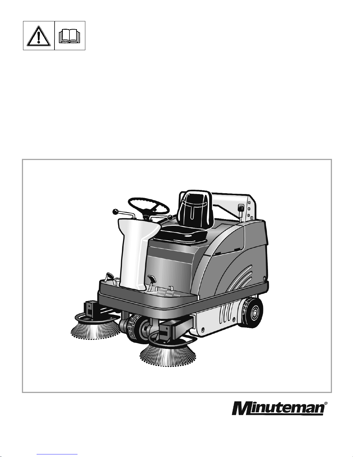
SW5X
Model: PB40PL, PB40PH
Instruction Manual
Introduction
Please be advised explicitly that
we cannot accept any legal issues out of the contents of this
manual.
If repair work has to be performed make sure that only genuine spare parts are used; only
genuine spare parts may guarantee a dependable machine.
Valid as of: March 2005
Dear customer,
It is our desire that the good cha-
racteristics of the SW5X should
justify the confidence you demonstrated by making this purchase.
Before first operation of your
SW5X, read these instructions
carefully. The manual provides
valuable information about operation, service and maintenance.
The symbol as used in this manual
identifies items relevant to safety.
Please observe the safety provisions (see chapter 1).
Before first operation of the machine,
read these instructions and safety information carefully and comply with
them.
2

Proper Use
The SW5X sweeper has been
exclusively designed for collecting
dry and moist matter from floor surfaces in e.g. factories, storage buildings, parking ground and pedestrian areas. Using the machine
beyond this scope of application
will be deemed improper use; The
manufacturer cannot be held liable
for consequential damages.
The term of proper use also includes operation, maintenance and
repair work to be performed in compliance with the manufacturer's
specifications.
The SW5X may be used by personnel only that are familiar with the
machine and aware of possible
hazards involved.
The applicable Accident Prevention
Regulations, Road Traffic
Regulations, and aspects of safety
and working medicine in vigour will
have to be complied with.
If modifications to the machine are
made in absence of the manufacturer's prior consent, the latter cannot be held liable for damage resulting from such unauthorized modification.
The machine has not been
designed for collecting
dusts which are detrimental
to health or explosive.
Notes on warranty
The terms of the sales contract apply.
Damages are not subject to warranty
if they are due to non-compliance
with the maintenance and service
provisions. The maintenance work
has to be performed by an authorized
service center and confirmed in the
"Maintenance certificate" which is the
warranty document.
The following is excluded from warranty:
fuses, natural wear, damages caused
by overload, inexpert handling and
unauthorised modification of the
machine. Moreover, any claim for
warranty cannot be accepted if damages at the machine are caused by fitting
parts or accessories without prior
and explicit consent or by non-compliance with the maintenance
instructions.
Inspection
Carefully unpack and inspect your
SW5X for shipping damage. Follow
unpacking instructions on shipping
pallet. Each unit has been tested
and thoroughly inspected before
shipment. Any damage is the responsibility of the delivery carrier who
should be notified immediately.
Proper Use
3

4 Operation . . . . . . . . . . . . . . . . . . . . .19
4.1 Controls . . . . . . . . . . . . . . . . . . . .19
4.2 Control Panel . . . . . . . . . . . . . . . .21
4.3 Empty Dirt Hopper . . . . . . . . . . . .26
4.4 Empty Dirt Hopper
Lift-Up Disposal . . . . . . . . . . . . . .26
4.5 Working with the machine . . . . . . .29
4.5.1 Before Start of Engine . . . . . . . . .29
4.5.2 Start Engine . . . . . . . . . . . . . . . . .29
4.5.3 Stop Engine . . . . . . . . . . . . . . . . .30
4.5.4 Sweep . . . . . . . . . . . . . . . . . . . . . .30
4.5.5 Stop and Park . . . . . . . . . . . . . . . .30
4.5.6 Displace . . . . . . . . . . . . . . . . . . . .31
4.5.7 Transport . . . . . . . . . . . . . . . . . . .32
5 Technical Data . . . . . . . . . . . . . . .32
6 Maintenance/Service . . . . . . . . .37
6.1 Maintenance Instruction . . . . . . . .37
6.2 Mount/Dismount Cylinder Broom .38
6.3 Adjust Sweeping Track . . . . . . . . .38
6.4 Sealing strips for Broom
Compartment . . . . . . . . . . . . . . . .40
6.5 Folding Apron Adjustment . . . . . . .40
6.6 Replace Side Brush . . . . . . . . . . .41
6.7 Dismount Plate Filter . . . . . . . . . .42
6.8 Basic Cleaning of Plate Filter . . . .44
6.9 Engine . . . . . . . . . . . . . . . . . . . . .45
6.9.1 Check Engine Oil Level . . . . . . . .45
6.9.2 Change Engine Oil . . . . . . . . . . . .46
6.9.3 Air Cleaner . . . . . . . . . . . . . . . . . .46
6.10 Hydraulic System . . . . . . . . . . . . .47
6.10.1 Check hydraulic Fluid-Level . . . . .48
6.10.2 Refill Hydraulic fluid . . . . . . . . . . .48
6.10.3 Change Hydraulic Fluid Filter . . . .48
6.10.4 Check and Refill Hydraulic
System Lift-Up Disposal . . . . . . . .49
6.11 V-Belt Drive . . . . . . . . . . . . . . . . . .50
6.11.1 Replace Cylinder Broom V-Belt . .51
6.11.2 Replace Side Brush V-Belt . . . . . .51
6.11.3 Replace Suction Fan V-Belt . . . . .52
6.11.4 Replace Hydraulic Pump V-Belt . .52
6.12 Electric System . . . . . . . . . . . . . . .53
6.13 Maintenance System . . . . . . . . . .54
7 Liquid propellant gas system . .56
8 Spare Parts . . . . . . . . . . . . . . . . .62
Contents
Introduction/Proper Use
Notes on Warranty
Inspection
1 Safty Information . . . . . . . . . . . . .5
1.1 General Safety Information . . . . . . .5
1.2 Safety and Warning Symbols . . . . .6
1.2.1 Generally Applicable Symbols . . . .6
1.3 Labels at the Machine . . . . . . . . . .7
1.4 Operation/Safety Information . . . .10
1.5 Cleaning Informaton . . . . . . . . . . .11
1.6 Maintenance instructon . . . . . . . .12
2 Description . . . . . . . . . . . . . . . . .14
2.1 Functional Descripton . . . . . . . . . .14
2.2 Cylinder Broom . . . . . . . . . . . . . . .15
2.3 Side Brush . . . . . . . . . . . . . . . . . .15
2.4 Filter System/Dust Evacuation . . .15
2.5 Shaking System . . . . . . . . . . . . . .15
2.6 Steering . . . . . . . . . . . . . . . . . . . .15
2.7 Wheels . . . . . . . . . . . . . . . . . . . . .15
2.8 Brake . . . . . . . . . . . . . . . . . . . . . .16
2.9 Travel Drive Assembly . . . . . . . . .16
2.10 Hydraulic System Lift-Up
Disposal . . . . . . . . . . . . . . . . . . . .16
3 First Operation . . . . . . . . . . . . . .17
3.1 General . . . . . . . . . . . . . . . . . . . . .17
3.2 Refill Fuel . . . . . . . . . . . . . . . . . . .17
3.3 Check Engine Oil Level . . . . . . . .18
4
Safety Information
1 Safety Information
1.1 General Safety Information
Apart from the instructions contained
in this manual, the general safety
instructions and accident prevention
regulations, as imposed by law will
have to be complied with. Do not put
the Manual aside without reading it
even if you used similar sweepers
before. Take the time to read them
now and save time later. Machines
with known defects must not be used.
It will be of essence to make yourself
familiar with all accessories and controls and their functions before you
start working. Avoid the mess of
having to read this book while trying
to run the machine.
Using the machine in areas with
explosion hazard, on public roads
and places is prohibited.
The operator has to use the machine
within its design limits.
Shut the motors down before transporting the machine.
Keep clear of hazard zone!
Before commencing work, the operator has to make sure that the SW5X
and its accessories are in proper and
safe condition.
Warning and instruction labels attached to the machine contain important information about safe operation.
Illegible or lost labels have to be
replaced.
Make sure that all covers
are fitted before starting to
sweep.
Provide for sufficient
ventilation when sweeping
indoors (dust and
combustion gas).
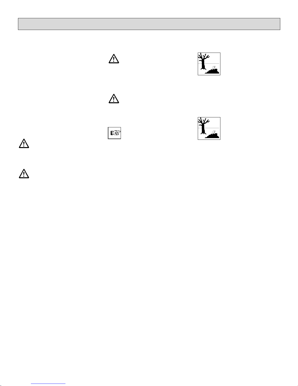
Pinching and shearing hazard. Provide for required
safe distance before lifting
or lowering the dirt hopper.
Shut down the engine before re-fuelling.
Smoking and handling open
flames is prohibited when
filling fuel tanks or when
working at or in the vicinity
of components containing
fuel.
5
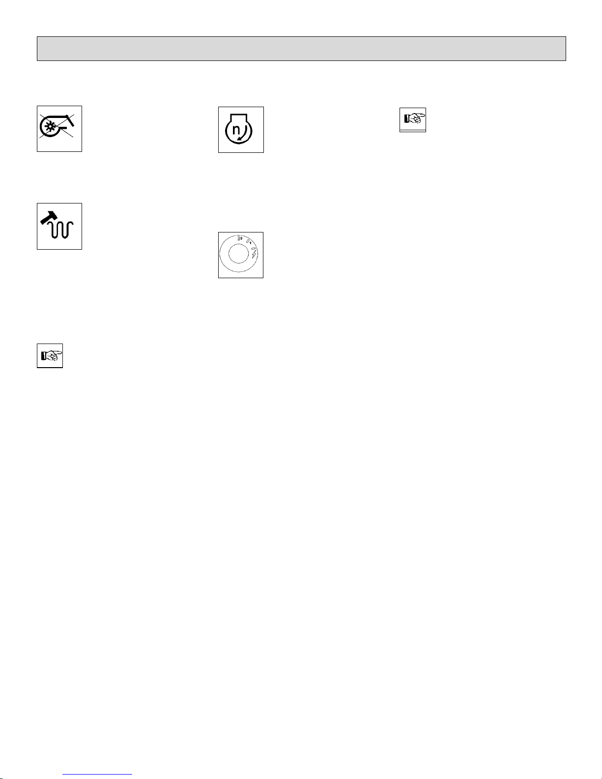
1.2 Safety and Warning Symbols
1.2.1Generally Applicable Symbols
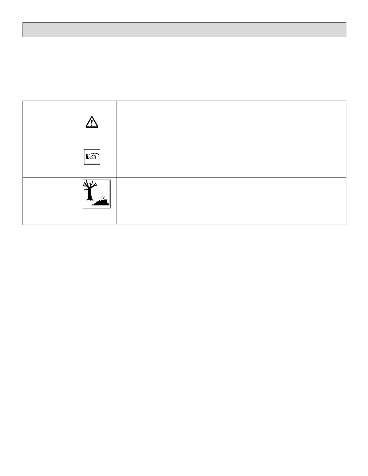
All paragraphs in this manual referring to your personal safety, the safety of your machine and the environment protection are attributed one of
the following warning symbols:
Safety Information
Hazardous for....
persons and
goods
the machine
the environment
Description
dangerous situation
caused by misuse inaccurate adherence of instructions or
prescribed work routine
important information on handling the machine in order to
maintain operability
due to use of substances representing an inherent danger to
health of environment
Symbol
DANGER
CAUTION
Ecological hazard
6
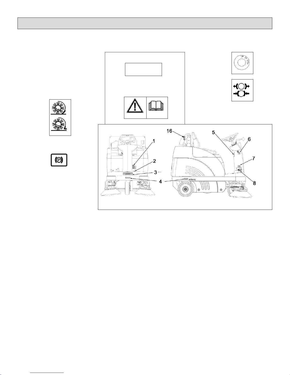
1.3 Labels at the Machine
The following safety and information
signs are legibly attached to the
machine. Missing or illegible stickers
have to be replaced.
Folding apron (1)
Parking brake (2)
Nameplate front (3)
Inflation pressure (4)
Read and observe operator's
Manual (5)
Ignition lock (6)
Brake (7)
Noise power level (8)
91 dB (A)
Safety Information
Fig.1
90 PSI
7
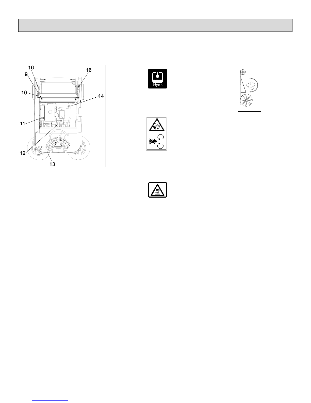
1.3 Labels at the Machine
Fig. 2 Safety and information
signs
Hydraulic fluid (9)
Rotating parts (10)
Burning surface (11)
Cylinder broom wearing take-up (12)
Nameplate (13)
Safety Information
8
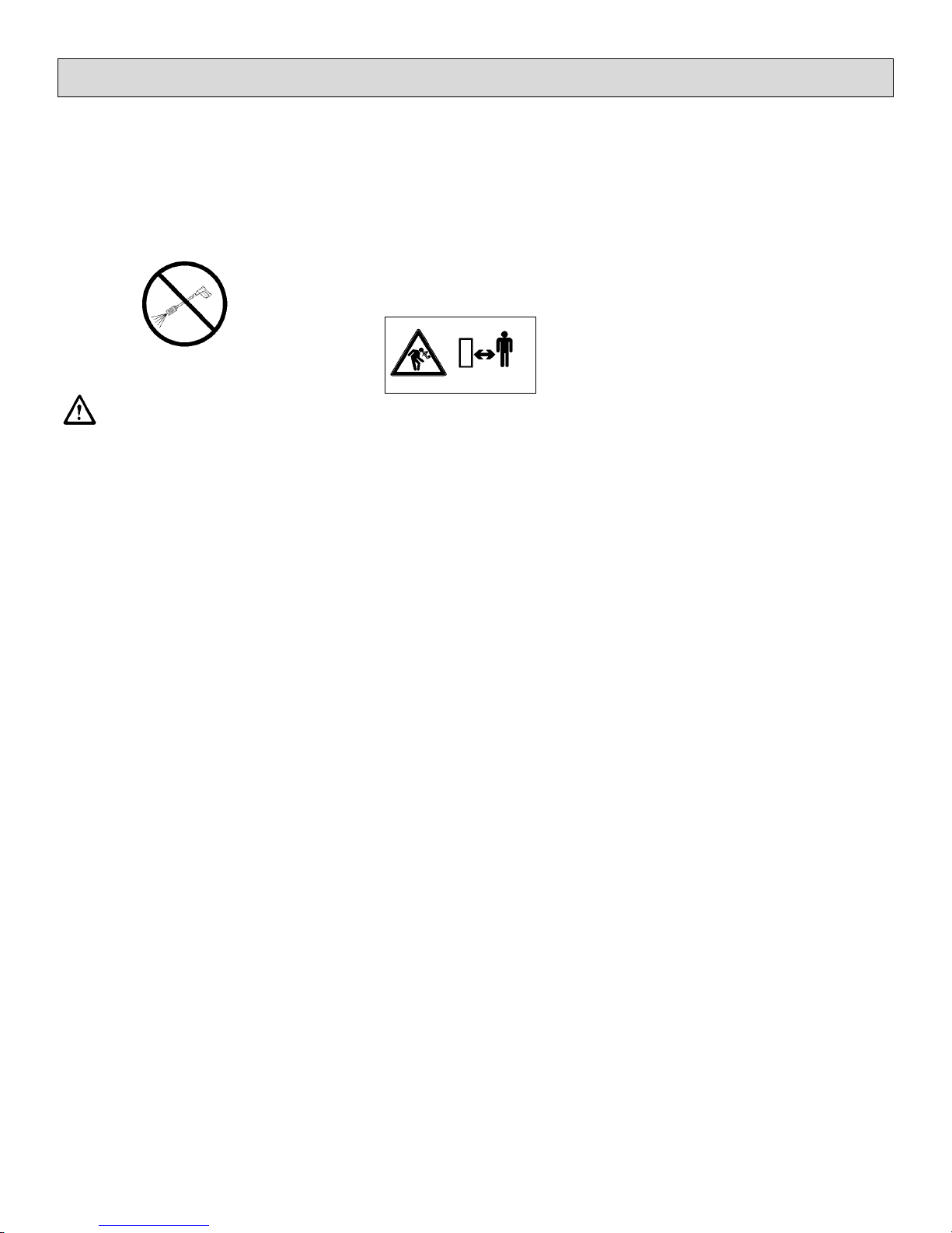
1.3 Labels at the Machine
High-pressure cleaner (14)
Do not clean by means of
high pressure cleaner or
vapour jet.
Pinching hazard (16)
(Lifted-Up Disposal)
Safety Information
9

1.4 Operation/Safety
Information
Vacuum sweepers may be run by
qualified personnel only; such personnel will have to have evidenced
their qualification for running the
machine to the owner or his authorized representative; operators explicitly will have to be instructed by the
owner or his authorized representative to use the machine.
The machine may be used
for cleaning such surfaces
approved by the owner or
this authorised representative for operation of vacu
um sweepers.
Before starting the engine,
switch off all drives
Transporting persons on the machine
is prohibited. Ride-on machine types
are to be started with the driver being
seated.
Never leave the machine unattended
before the motors are off and the machine is protected against unintended
movements.
To prevent the machine from unauthorized use, pull the control key to block
all drives.
Shut down the motors before transport of the machine. The driver has to
take account of local conditions and
when operating the sweeper he has
to watch out for other persons, especially children.
Do not open hood or
fairings with the machine
running.
This machine must not be
used as dust-evacuating
machine with dust filter insert (separator) to collect
dusts which are hazardous
to health.
Compared to four-wheeled
vehicles, driving stability of
three-wheeled vehicles is
reduced. We thus recommend:
- do not negotiate curves at
high speed.
- do not turn at slopes but
on level ground only
- ride up- or downhill
straight.
Safety Information
10

11
Safety Information
Warning and instruction labels attached to the machine contain important information about safe operation
Provide for sufficient ventilation when sweeping indoors (dust and combustion
gas).
Proceed to filter shaking only if the dirt hopper is in closed position.
1.5 Cleaning Information
The machine is splash-proof (IPX3).
Do not clean the SW5X by
means of high pressure cleaner or vapour jet.
Proceed to cleaning of the
dirt hopper in regular intervals to preclude formation of
bacterial deposits.
1.6 Maintenance Instructions
A good approach to prevention of
accidents is proper maintenance of
the machine.
Before proceeding to repair or maintenance work remove the key.
Use appropriate tools for maintenance, service, setting etc.
As far as aspects of safety are concerned, spare parts will have to be at
least of the same quality as the genuine spare parts.
Switch off the motors before maintaining the machine
or replacing parts of it. Turn
off the machine and pull the
key.
Check hydraulic hoses and
lines for leakage or damages in regular intervals. Replace defective hoses and
lines immediately.
Before changing wheels
protect the machine against
rolling by placing wedges.
Proceed to wheel changing
when the machine is on level and solid ground.
Do not repair the pneumatic
tires mounted to the machine yourself. Dismount the
wheel and take it to repair to
a tire workshop.
Use of other than the cylinder brooms and side brushes approved by the manufacturer is not acceptable
(see technical data) since
use of other cylinder
brooms and side brushes
may affect your safety.
When handling lubricating agents, the applicable regulations for
protection of the environment and prevention of fire have to be
complied with. Provide
for disposal of used oil
and grease in accordance with the provisions imposed by law.
Collect cleaning
agents, oil, fuel oil, grease etc. and provide for
adequate disposal. Wipe away spilled substances.
Safety Information
12
Before commencing any
work on the electric system
disconnect battery (neg. lead) of the SW5X and pull the
ignition key.
Do not keep batteries dsicharged for a longer period;
always recharge them as
soon as possible.
Top with distilled water only. Never refill battery acid
in battery cells of perfect
condition.
Keep batteries dry and clean and clear of soiling such
as e.g. metallic dust to avoid leakage current.
Do not place metal objects
or tools onto batteries.
Short-circuit and deflagration hazard.
Spilled (straight) battery
acid must not get into the
sewage system before having been neutralised. Comply with the regulations imposed by law and observe
local provisions.
Battery acid is highly
caustic (keep clear of
children).
When checking the battery
acid level, wear safety glasses. If acid splashes get into the eyes rinse with clear
water for 15 minutes and
contact a doctor immediately.
Use appropriate protective
means (e.g. protective gloves or finger-stalls) when
handling battery acid.
Do not use open flames
(explosion hazard).
Safety Information
13
2 Description
2.1 Functional Description
Principle
The side brush is used to collect dirt
at borders and to enlarge the working
width as well as to increase the area
performance on large surfaces.
The cylinder broom casts the debris
overhead into the dirt hopper. The collected fine dust is evacuated by the
suction fan and separated by a filter
system. The air returned into the environment is clean.
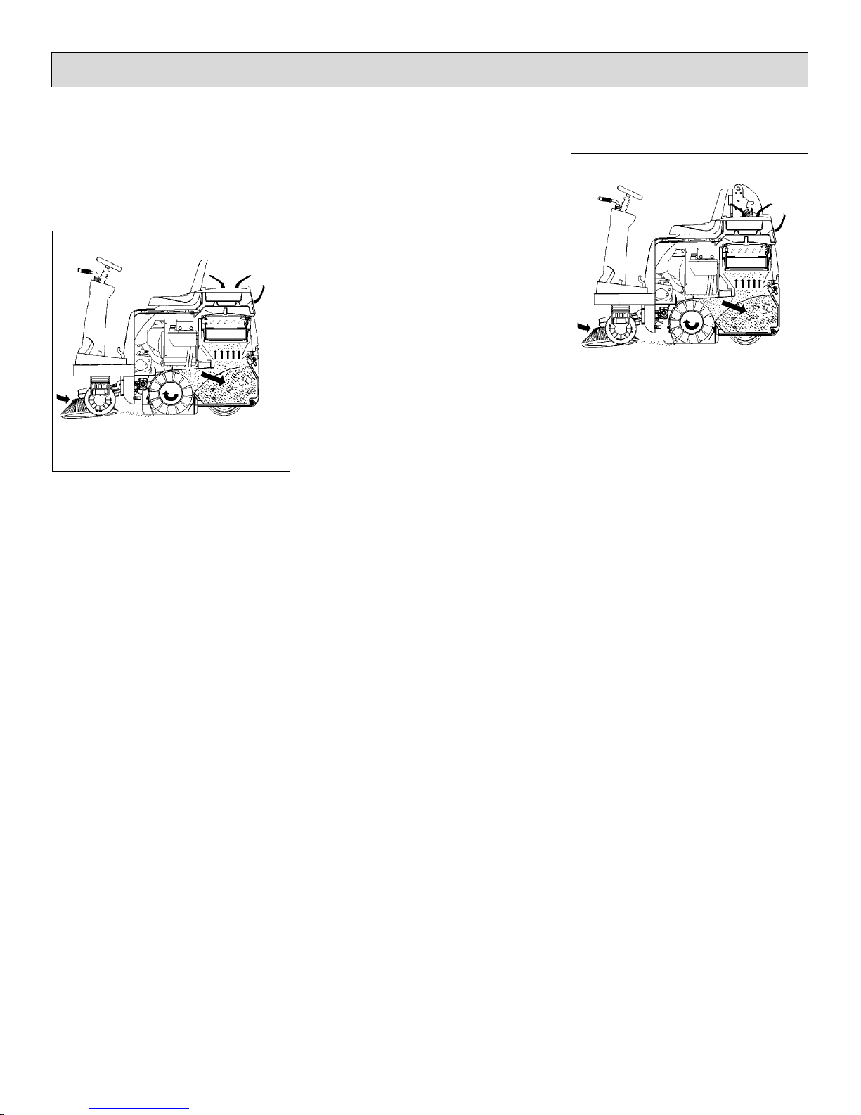
Dirt disposal at the SW5X is realized
via two dirt hoppers (2x30 litres)
which are to be emptied manually.
Dirt disposal at the SW5X (Lift-Up
Disposal) is realized via lift-up disposal (lift-up height > 1350mm) directly
into standard waste containers.
Description
Fig.3
Fig.4
14

2.2 Cylinder Broom
The cylinder broom is equipped with
12 rows of bristles arranged in
V-shape.
The cylinder broom width amounts to
27.6 in. (700mm) and its diameter to
13.6 in. (345mm).
2.3 Side Brush
At the standard version, the side
brush is located at the front right of
the machine. The operator lifts and lowers it by hand lever.
The side brush has a light inclination.
The swinging area of the side brush
arm is limited by stop screws.
The side brush is driven by V-belt.
For special application, fitting of a
second side brush at the left is possible.
2.4 Filter System / Dust
Evacuation
The filter system is located in the filter case above the dirt hopper. The
suction fan transports the fine dust
raised by the cylinder broom to the
plate filter where it is separated. The
fine dusts sets at the outsides of the
filter blades.
In case of heavy dust development, check and clean
the plate filter at regular
intervals.
2.5 Shaking System
Due to normal working vibration the
set dust partly falls off into the dirt
hoper. To ensure working in a dustfree environment, however, actuate
the shaking system regularly, or after
request by the pilot lamp at the latest.
2.6 Steering
Steering is controlled mechanically
from steering wheel to front wheel via
chain. This chain is to be re-adjusted
as required.
2.7 Wheels
Pneumatic tyres with hose, size.
4.00 - 4 6PR
Inflation pressure: 90 PSI (6 bar)
Solid rubber tyres (Option)
Description
15

2.8 Brake
The SW5X is equipped with a service
brake.
This brake has been constructed as
shoe brake and equally serves as
parking brake.
It is located in the rear wheels and is
actuated via cables.
A special adjustment screw is situated at the right-hand rear wheel.
Any work at the braking
system has to be executed
by qualified persons in a
qualified workshop only.
2.9 Traction Drive Assembly
The SW5X is equipped with a hydrostatic drive assembly which is driven
by the combustion engine via pump.
2.10 Hydraulic System
Lift-Up Disposal
The hydraulic system comprises a
compact unit (hydraulic pump with
hydraulic tank), the hydraulic hoses
and a hydraulic cylinder.
Hydraulic fluid: Mobiloil DTE 15 M
The named hydraulic fluid has been
filled in the hydraulic system in the
factory.
Filling of hydraulic tank: 0.2 gal. (0.76
litre)
Description
16
3 First Operation
The SW5X has been extensively
tested and submitted to a functional
check before delivery.
Only qualified personnel of your local
contract dealer are allowed to proceed to first operation. After shipping
of the machine, we advise your contract dealer. He will contact you to
make a date for briefing lessons.
3.1 General
Smoking and handling open
flames is prohibited when
filling fuel tanks or when
working at or in the vicinity
of components containing
fuel.
Do not use the SW5X at ambient temperatures of more
than 104°F (40°C).
Do not start the machine at
temperatures of 5°F (-15°C)
or less.
Liquid propellant gas
system: refer to LPG operating instructions.
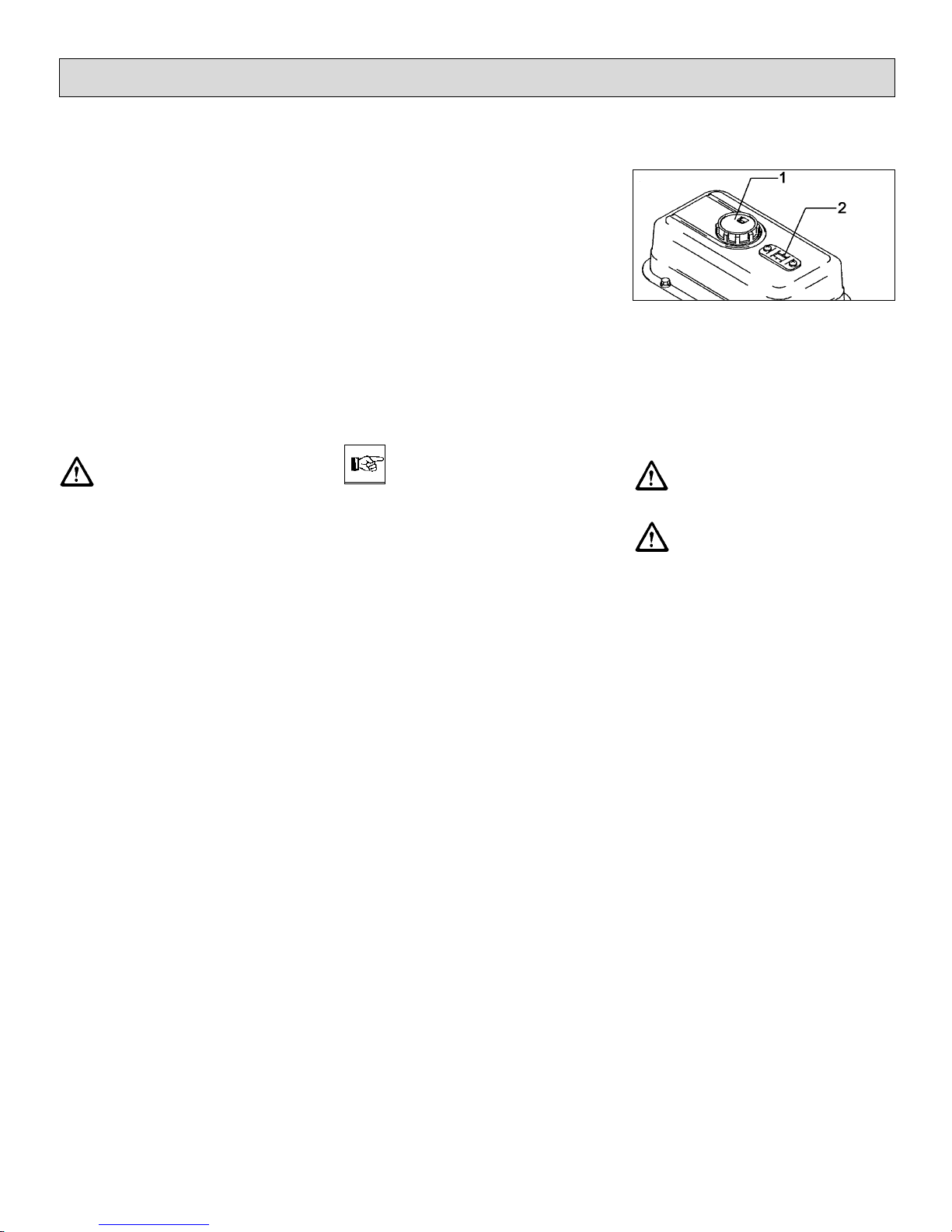
3.2 Refill Fuel
The fuel tank is located under the foldable seat hood.
Use clean fuel oil only. Store fuel in approved and closed reservoirs only.
- Turn engine off
- Secure machine by engaging the
parking brake.
- Pull ignition key.
- Fold back seat hood.
Fuel tank
- Check filling level at the filling level
indicator (Fig. 5/2).
- Remove tank lid (Fig. 5/1) before
filling.
Turn engine off before filling
fuel.
Smoking and handling open
flames is prohibited when
filling fuel tanks or when
working at or in the vicinity
of components containing
fuel.
First Operation
Fig.5
17
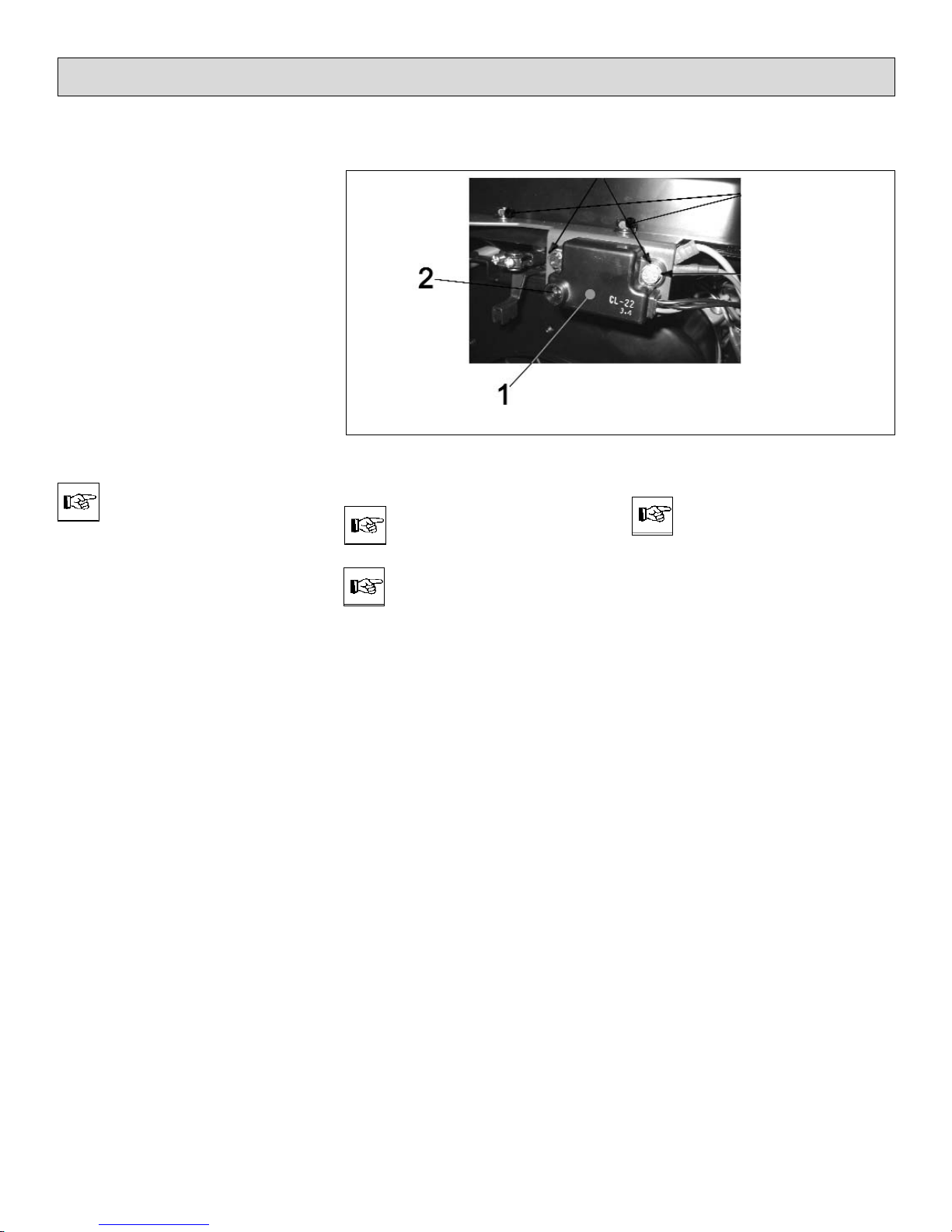
3.3 Check Engine Oil Level
- Engine oil has been filled in the factory.
- For safety reasons, check the engine oil level (refer to paragraph
6.9.2, Fig. 23/2)
- In order to protect the engine, it is
switched off or cannot be started if
engine oil level is insufficient.
This function is controlled by a low
oil level switch (Fig. 0/1) at the engine. A red pilot lamp (Fig. 0/2) is situated at this switch and lights simultaneously in case of insufficient
oil level.
Before the machine is operable again, refill oil until
the prescribed level is attained.
Engine Oil Level
Use clean oil only for
refilling.
Do not use used oil.
Store oil in approved and
closed reservoirs only.
First Operation
Fig.0
18
4 Operation
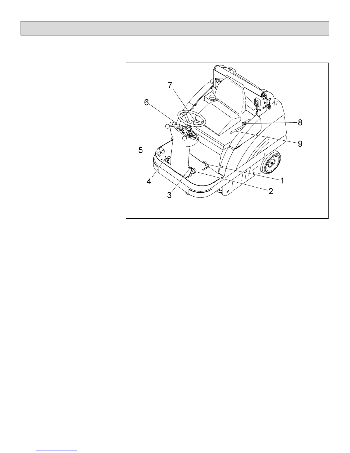
4.1 Controls
1 Actuator for folding apron
2 Service brake lock
3 Service brake/parking brake pedal
4 Drive pedal, reverse
5 Drive pedal, forward
6 Control panel
7 Seat adjustment
8 Safety knob, lock for release of
swinging dirt hopper function
(Lift-Up Disposal)
9 Release lever for swinging dirt
hopper function (Lift-Up Disposal)
Operation
Fig.6
19

1 Actuator for folding apron
to open and close the folding apron
for collecting coarse dirt.
2 Service brake/parking brake lock
to lock the service brake/parking
brake. If locked, the service brake
works as parking brake. Release
the lock by depressing the service
brake pedal (3).
3 Service brake/parking brake pe-
dal
to actuate the service brake at the
rear wheels. Before leaving the machine unattended, engage the service brake and lock.
4 Drive pedal, reverse
to change direction to reverse ride
with continuous regulation of riding
speed at the same time. If the driver releases the pedal it returns to
initial position and the machine
slows down to standstill.
5 Drive pedal, forward
to change direction to forward ride
with continuous regulation of riding
speed at the same time. If the driver releases the pedal it returns to
initial position and the machine
slows down to standstill.
6 Control panel
Refer to chapter "Control panel"
7 Seat adjustment
to adjust the seat position to drivers
of different height.
Adjust the seat so as to allow the
driver being comfortably seated and
attaining all elements required for
operation.
- Adjust seat lengthwise: push lever
slightly to the right and displace seat forwards or backwards to the required position. Then let the lever
catch again.
8 Safety knob, lock for release of
swinging dirt hopper function
to release the lever for swinging dirt
hopper function.
9 Release lever for swinging dirt
hopper function
to swing the dirt hopper
Operation
20
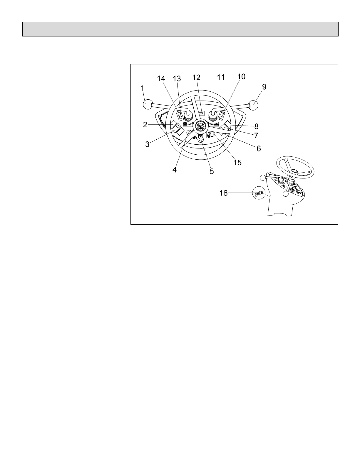
4.2 Control Panel
1 Cylinder broom lever
2 Release of lifted-up disposal func-
tion
3 Horn
4 Suction fan/shaking system knob
5 Choke flap knob
6 Flashlight (option)
7 Lighting (option)
8 Lift and lower (Lift-Up Disposal)
9 Side brush lever
10 Pilot lamp, parking brake
11 Battery charge status indicator
12 Hourmeter
13 Pilot lamp, fan
14 Pilot lamp, shaking system
15 Engine speed regulation knob
16 Ignition switch
Operation
Fig.7
21
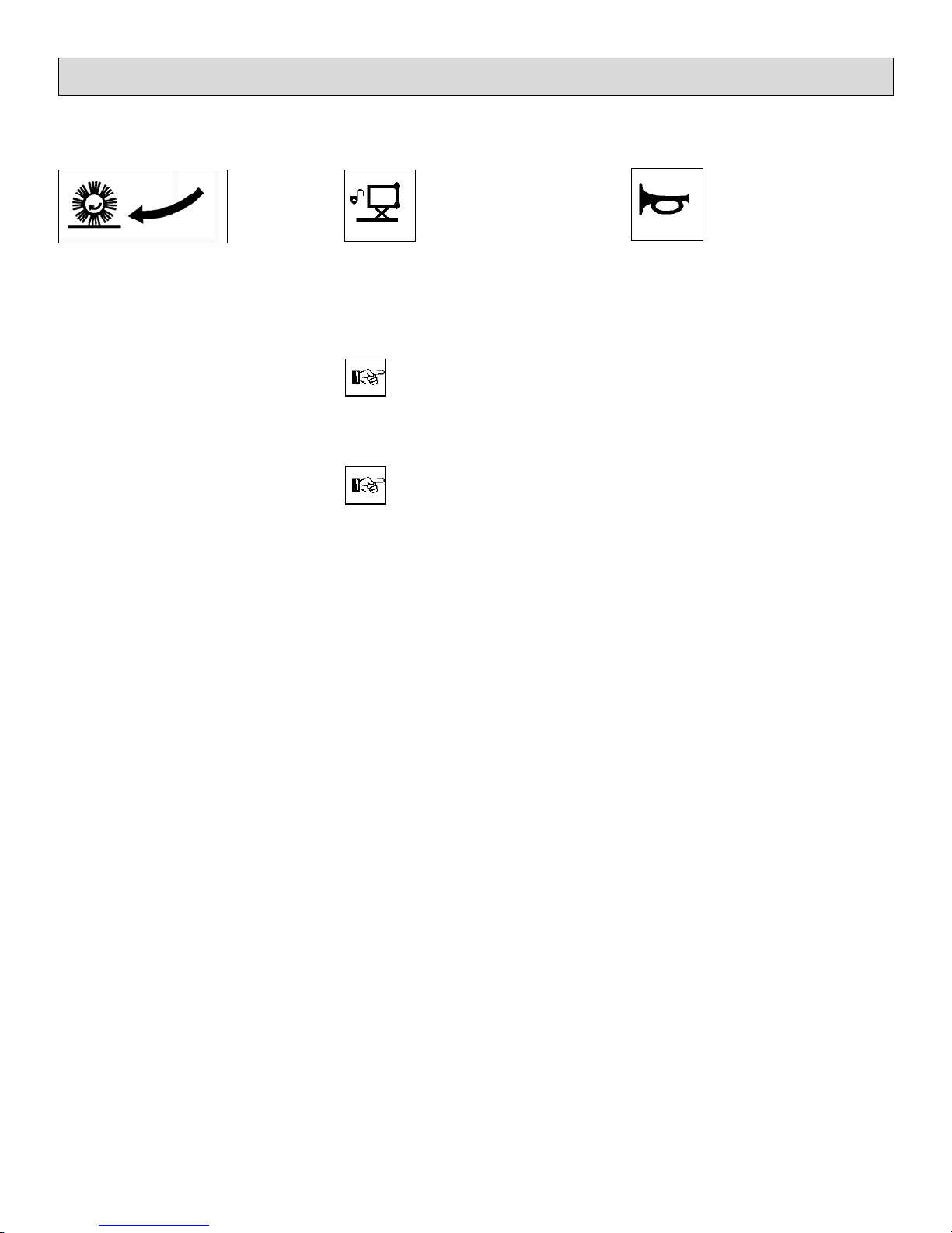
1 Cylinder broom lever
to lift and lower as well as to
switch on and off the cylinder
broom and the side brush.
- Lower cylinder broom as well as
switch on cylinder broom and side
brush
= push lever
- Lift cylinder broom as well as switch
off cylinder broom and side brush
= pull lever
2 Release for lifted-up disposal
function
to release the lifted-up disposal
function for lowering of lifting.
Has to be actuated before
pressing the key for
lifting/lowering lifted-up disposal function. Hold the key
during lifting/lowering.
Before changing lifting to
lowering or vice versa, the
"Release Lifted-Up Disposal" key has to be released
once and pressed again
3 Horn
An acoustic signal sounds upon
actuation of this button.
Operation
22
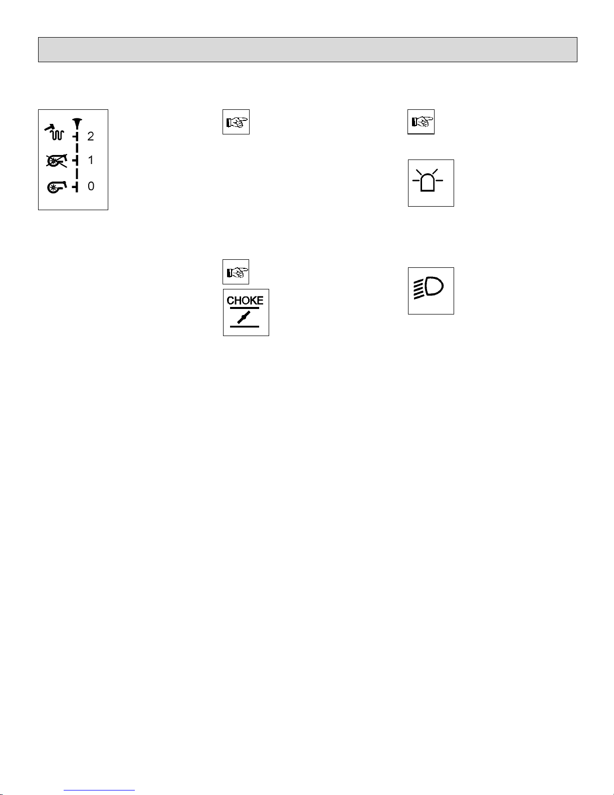
4 Suction fan/shaking system
knob
Knob position (from bottom to top):
Pos. 0 Activated vacuuming function
(close flap before sweeping
dry surfaces or collecting
dry dirt).
Pos. 1 Deactivated vacuuming
function (open flap before
sweeping wet surfaces and
collecting wet dirt).
Pos. 2 Shaking system ON (pull
knob to stop and then
release)
After jolting, the knob is to
be kept in position 1 for about 10 seconds.
Reduce engine speed to id-
ling in order to optimize the
cleaning result in case of
heavy fine dust load.
If the yellow pilot lamp (Fig. 7/13)
lights, actuate the shaking system
(position 2).
In this position, the shaking system is
operable and proceeds to jolting in 7
repeated intervals.
Do not hold the knob in
position 2!
5 Choke flap knob
to actuate the choke flap (cold
start)
- Knob down - choke not actuated
- Knob pulled up - choke actuated
for cold start.
If the engine has already attained temperature, do not
actuate the choke flap and
start with full throttle.
6 Flashlight (option)
to switch the flashlight ON/OFF.
7 Lighting (option)
to switch the driving headlight
ON/OFF.
Operation
23

8 Lift and lower (lifted-up dispo-
sal)
to lift and lower the dirt hopper.
Lift the dirt hopper by pressing the
key until the desired height for lifting-out is attained.
When lowering the dirt hopper make sure to hold the key pressed
until the hopper has contact with
the frame.
Actuate release key for lifted-up disposal and hold
before lifting or lowering.
9 Side brush lever
to lift and lower the side brush.
- Lower side brush
= push lever
- Lift side brush
= pull lever
10 Pilot lamp, parking brake (red)
lights upon actuation of the parking brake Extinguishes upon
release of the parking brake.
11 Battery charge status indicator
(red)
lights upon actuation of the ignition
switch and has to extinguish as
the engine fires.
12 Hourmeter
indicates the operating hours. The
counter works only if the driver is
seated and the ignition is ON.
Operation
24
13 Pilot lamp, suction fan (orange)
lights if the suction fan is not activated.
14 Pilot lamp, shaking system (yel-
low)
Proceed to jolting of the filter
system upon lighting of this pilot
lamp by actuating the knob
(Fig.7/5).
The pilot lamp flashes during the shaking procedure
and extinguishes after filter
has been cleaned. Jolting is
effectuated in 7 intervals.
15 Engine speed regulation knob
to adjust the engine speed. Service speed is attained by pulling
the knob up.
16 Ignition switch
to switch ignition on and off, to
start and stop engine and to secure it against unauthorised use.
For safety reasons, the
SW5X has been equipped
with a seat contact switch.
Starting the engine is possible only after the driver
has taken place on the seat.
If seat contact is interrupted
while the engine is running,
the combustion engine of
the SW5X has to be re-started.
Operation
25
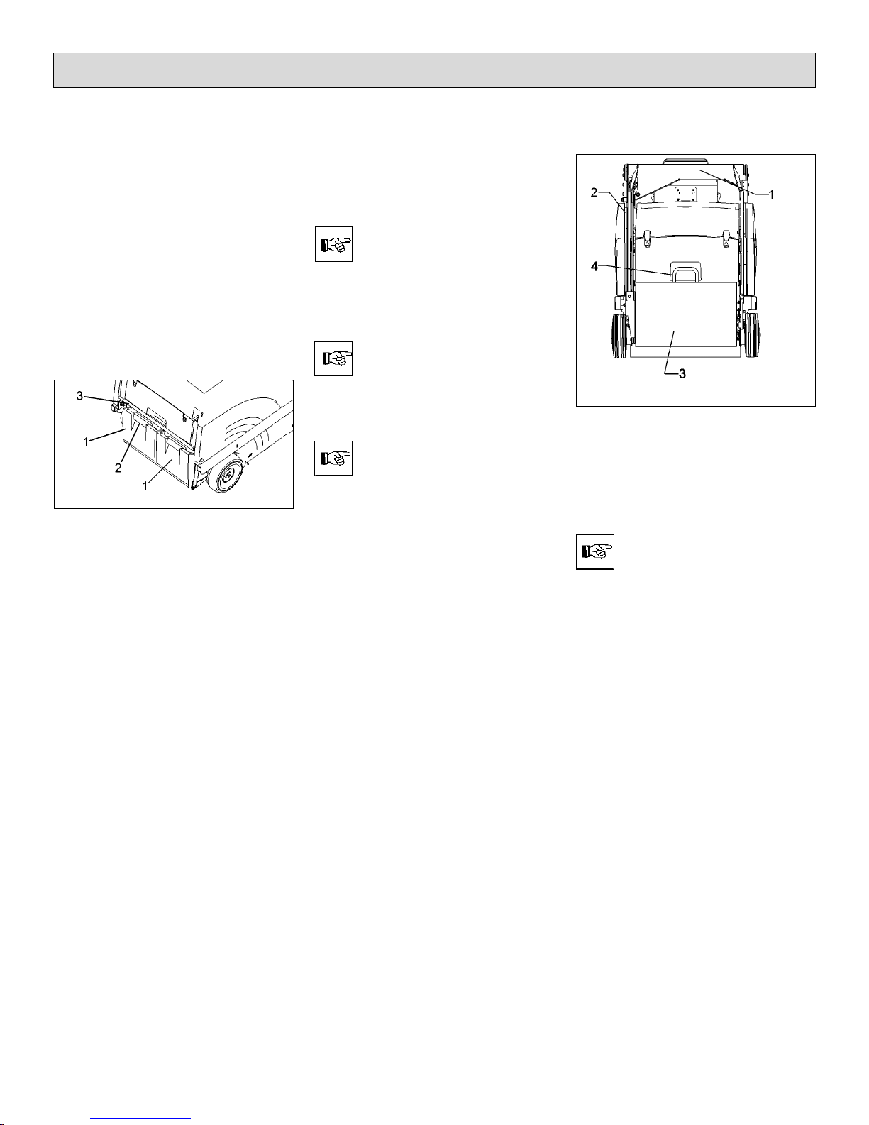
4.3 Empty Dirt Hopper
- Fold bow (Fig. 8/3) up
= the dirt hoppers (Fig. 8/2) are lowe-
red.
- Use the recessed grip (Fig. 8/1) of
one of the hoppers to lift it lightly
and extract it.
- Take the hopper at its bow-type
handle to disposal and empty.
- Empty second dirt hopper as described above.
- Re-insert dirt hopper (Fig. 8/2) and
fold down the bow (Fig. 8/3).
1 Recessed grip in dirt hopper
2 Dirt hopper
3 Bow to lift/lower dirt hoppers
Clean dirt hoppers at
regular intervals.
4.4 Empty Dirt Hopper (Lift-Up
Disposal)
Lift side brush and cylinder
broom before emptying of
the dirt hoppers.
If the hopper is lifted with
the cylinder broom still running, the engine is switched
off.
1 Lift-out arm
2 Lift-out cylinder
3 Dirt hopper
4 Bow-type handle
Clean dirt hopper at regular
intervals.
Operation
Fig.8
Fig.9
26
Riding with the lifted hopper reduces stability of the
machine significantly. For
this reason, do not lift the
hopper but just before emptying. Before lifting the hopper, the operator has to make sure that no persons or
objects are behind or next
to the machine. Stop the
machine on level ground
before lifting the hopper.
When the hopper is lifted,
the operator has to ride the
machine slowly.
Keep clear of the hazard
zone!
Pinching and shearing hazard. Provide for required
safe distance before lifting
or lowering the dirt hopper.
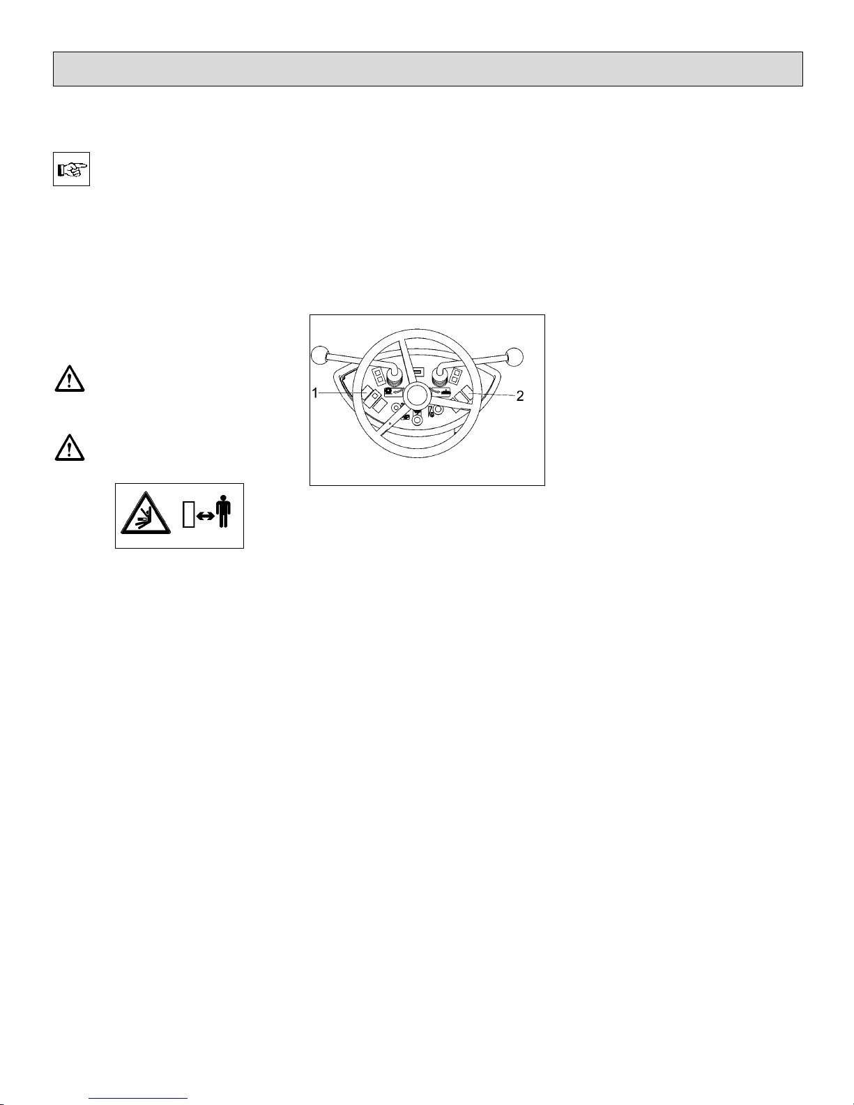
Control panel (Lift-Up Disposal)
1 Release switch for lifted-up dispo-
sal function
2 Dirt hopper, lift and lower
Proceed to emptying of the dirt
hopper as follows:
- Lift and switch off side brush and
cylinder broom
- Proceed to shaking of the filter
system
- Actuate switch (Fig. 10/1) and hold
(dirt hopper is released)
- Actuate switch (Fig. 10/2) by
pushing = lift dirt hopper
- Dirt hopper (Fig. 9/3) is lifted-out
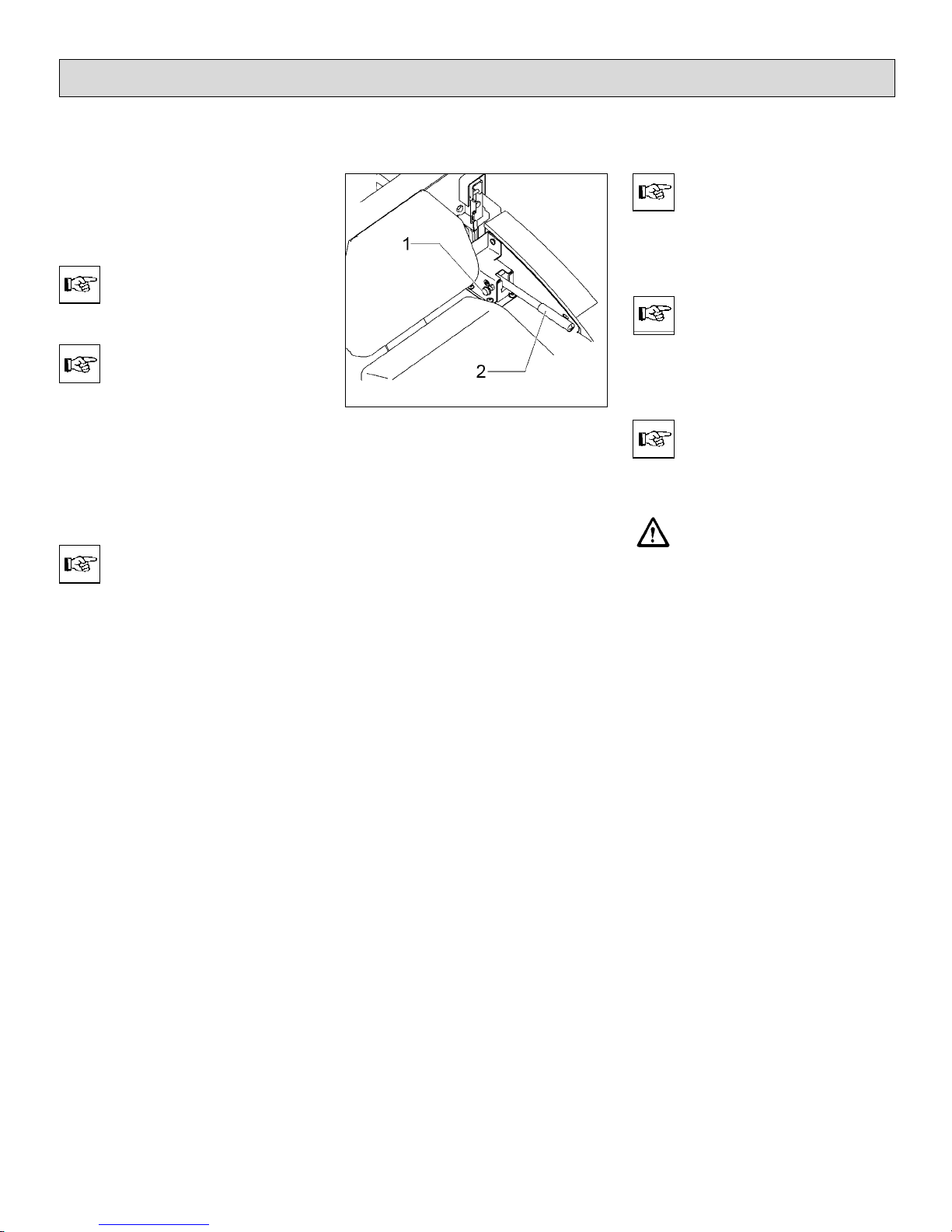
- Back the SW5X until the dirt hopper is positioned above the container for disposal.
- Pull the safety knob (Fig. 11/1) of
the release lever (Fig. 11/2).
- Release swinging of the dirt hopper by release lever (Fig. 11/2).
- Forward the SW5X after emptying.
Operation
Fig.10
27
- Lower dirt hopper by actuating
switch (Fig. 10/1) and switch (Fig.
10/2); pull lever = lower dirt hopper
Observe the information given in paragraph 4.2/2 on
releasing of lifted-up disposal.
If the hopper is lifted, the
sweeping function is blokked. If the main broom is lo-
wered even if the hopper is
lifted, the combustion engine stops. Starting is then
possible only after sweeping function is turned off
(main broom lever in OFF
position) or the hopper is
lowered. (Under condition
that the driver is seated)
Lifted-up disposal function
is blocked as long as sweeping function is ON.
Release lever, swing dirt hopper
1 Safety knob
2 Release lever, swing dirt hopper
If the cylinder broom is
switched on with the dirt
hopper being lifted, the engine stops.
Should the dirt hopper not
be completely emptied after
swinging, proceed to manual shaking with the handle
(Fig. 9/4).
Clean the dirt hopper in regular intervals.
The dirt hopper is approved
only for a max. filling of 18.5
gal (70 litres) but not more
than a weight of 242.5 lb
(110 kg).
Operation
Fig.11
28

4.5 Working with the machine
The driver is requested to carefully
read this manual. All controls are
marked with easy-to-understand symbols that ease familiarization. First
driving attempts should be limited to
clear areas until you are familiar with
all controls and their functions.
Please comply with the following safety provisions:
When working with the
SW5X all safety measures
generally applicable for
handling vehicles have to
be observed. No passenger
transport is admitted with
the SW5X. Warning and instruction labels attached to
the machine contain important information about safe
operation and guarantee
your personal safety. Before
commencing work, the operator has to make sure that
the machine and its accessories are in proper and safe condition and
comply with the provision
for safety at work. Do not
operate the SW5X without
protective devices.
4.5.1 Before Start of Engine
Open seat hood and check the following:
- Engine oil level
- Visual check of the V-belts
- Fuel filling
- Open fuel cock (is located at a slot
of the air cleaner)
- Close seat hood
4.5.2 Start Engine
For safety reasons, the SW5X is
equipped with a seat contact switch.
Starting the engine is possible only
when the driver is seated.
- Switch all levers and switches to
neutral position. Actuate parking
brake.
- Actuate choke (with cold engine
only)
- Turn ignition key to switch on
ignition
- Continue turning ignition key clok-
kwise to start engine.
If the starting procedure
has to be repeated or if the
engine stops, re-starting is
possible only after ignition
has been turned off. The ignition lock is equipped with
a protection to preclude repeated ignition with the engine running.
Operation
open
closed
29

Interruption of the starting
procedure after 10 seconds
and brief pause between
starting cycles is recommended to save the battery.
- Let the engine run and then slowly
press the choke knob down.
4.5.3 Stop Engine
- Turn ignition key counter-clockwise.
4.5.4 Sweep
- Start engine
- Adjust service speed
In initial position, vacuuming is activated. If the collected dirt is wet, open the
flap.
- Lower cylinder broom and side
brush.
- Release parking brake.
- Slowly depress drive pedal until
desired speed has been attained.
- Regularly actuate shaking device to
clean filter.
- Check filling level of the dirt hopper
and empty if required.
Refer to LPG operating instructions for information
on how to start machine
equipped with liquid propel-
lant gas system.
4.5.5 Stop and Park
- Release drive pedal which returns
automatically into its neutral position and the machine slows down to
standstill.
- Actuate parking brake
- Lift side brush and cylinder broom
- Turn engine off
Slowing down the SW5X is
possible by applying opposite forces with the drive
pedal or by using the service brake.
When leaving the machine
unattended, pull key in order to preclude unauthorized use.
Close the fuel cock in case
of long-term standstill of
the machine.
Operation
30
 Loading...