

Page 1
SCV 28/32 RIDER SCRUBBER
OPERATION
■ SERVICE ■ PARTS ■ CARE
Page 2
(
)
This manual is furnished with each new MINUTEMAN SCVTM 28/32. This provides the necessary operating
and preventive maintenance instructions. Operators must read and understand this manual before operating
or servicing this machine.
This machine was designed to give you excellent performance and efficiency. For best results and minimal
cost, please follow the general guidelines below:
• Operate the machine with reasonable care.
• Follow the manufacturers suggested maintenance instructions as provided in this booklet.
• Use original Minuteman supplied parts.
TECHNICAL SPECIFICATIONS
Model SCVTM28/32
Model No. SC280000QP / SC280001QP / SC32000QP / SC320001QP
SC280000CE / SC280001CE / SC320000CE / SC320001CE
Current 65 Amps
Voltage, Batteries 36 volts, 6-6volt
Battery Capacity 370 AH
Sound Level 72 dB
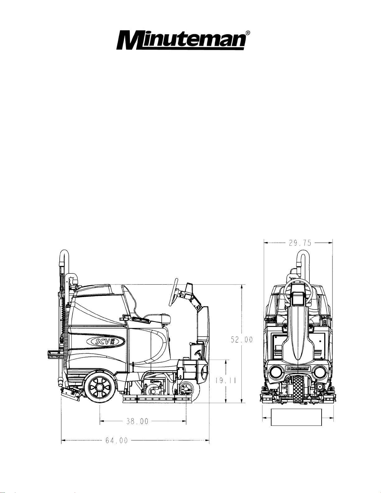
Dimensions (LxWxH) 64” x 31” x 54” (160cm x 78.74cm x 137cm)
Gross Weight 1,495 lbs (678 kg) with batteries
793 lbs (360 kg) without batteries
Working Grade Transport 16% (10°)
Working Grade Cleaning 10% (7°)
Wheel to Floor Pressure 64 PSI Front, 69 PSI Rear
31.00 (SCV 28)
SCV 32
35.00
2
Page 3
3
Page 4

TABLE OF CONTENTS
Operation, Illustration, Spare Parts, and Maintenance
IMPORTANT SAFETY INSTRUCTIONS.........1
FOR SAFETY DURING OPERATION: ........1
FOR SAFETY WHEN SERVICING
MAINTAINING MACHINE: ...........................1
INSPECTION....................................................1
ELECTRICAL ...................................................1
BATTERIES .....................................................1
OPERATOR RESPONSIBILITY ......................1
MACHINE COMPONENTS ..............................1
FRONT .............................................................1
MACHINE COMPONENTS ..............................2
REAR................................................................2
MACHINE COMPONENTS ..............................2
DRIVER’S COMPARTMENT ...........................2
CONTROL CONSOLE .................................3
Key switch................................................3
Off-aisle wand switch ...............................3
Headlight switch.......................................3
Main Keyboard.........................................3
Horn button ..............................................3
Directional switch .....................................3
MAIN KEYBOARD .......................................4
FULL FUNCTION MODE.........................4
DOUBLE SCRUB MODE.........................4
VACUUM ONLY MODE...........................4
TRANSPORT MODE ...............................4
INFORMATION BUTTON ........................4
WATER FLOW ADJUSTMENT ...............5
BRUSH PRESSURE ADJUSTMENT ......5
EMPTY SOLUTION TANK INDICATOR..5
RECOVERY TANK FULL INDICATOR ...5
LCD DISPLAYS............................................5
INFORMATION BUTTON ........................5
DIRECTIONAL SWITCH FORWARD......5
DIRECTIONAL SWITCH REVERSE .......5
FULL FUNCTION MODE.........................6
DOUBLE SCRUB MODE.........................6
VACUUM ONLY MODE...........................6
TRANSPORT MODE ...............................6
BRUSH PRESSURE ADJUSTMENT ......6
WATER FLOW ADJUSTMENT ...............6
OR
EMPTY SOLUTION TANK INDICATOR. 6
RECOVERY TANK FULL INDICATOR... 6
LOW BATTERY INDICATOR.................. 7
DIAGNOSTIC CODE............................... 7
FAULT / DIAGNOSTIC CODE ................ 7
OPERATION OF CONTROLS .................... 8
POWER SAVE MODE................................. 8
ACCELERATOR PEDAL ........................ 8
SEAT ....................................................... 8
STEERING WHEEL ................................ 8
MECHANICAL & PARKING BRAKE....... 9
EMERGENCY DISCONNECT BUTTON 9
CIRCUIT BREAKERS ................................. 9
BATTERY COMPARTMENT..................... 10
SCRUB DECK ........................................... 11
CYLINDRICAL....................................... 11
SCRUB DECK....................................... 11
DISC SCRUB DECK ............................. 11
SCRUB DECK INSTALLATION ................ 12
REAR SQUEEGEE ................................... 14
REAR SQUEEGEE COMPONENTS .... 14
REAR SQUEEGEE ADJUSTMENT...... 15
OFF-AISLE WAND................................ 15
OFF-AISLE WAND TOOL..................... 16
THE SCV RIDER ........................................... 17
MACHINE OPERATION............................ 17
AFTER USE: ......................................... 19
MAINTENANCE SCHEDULE.................... 20
LUBRICATING THE MACHINE ............ 20
GENERAL MACHINE
TROUBLESHOOTING
.............................. 21
SCV 28/32 FAULT / DIAGNOSTIC CODES . 23
EXPLODED VIEWS....................................... 25
MAIN ASSEMBLY I ................................... 25
MAIN ASSEMBLY II .................................. 27
MAINFRAME ASSEMBLY I....................... 29
MAINFRAME ASSEMBLY II...................... 30
FRONT DRIVE ASSEMBLY...................... 32
STEERING ASSEMBLY............................ 34
LCD HOUSING ASSEMBLY ..................... 36
SOLUTION TANK ASSEMBLY ................. 37
ELECTRICAL PANEL ASSEMBLY ........... 39
CONSOLE ASSEMBLY............................. 40
RECOVERY TANK ASSEMBLY I ............. 41
RECOVERY TANK II................................. 43
DIVERTER ASSEMBLY ............................ 44
BATTERY BOX ASSEMBLY ..................... 45
PUMP ASSEMBLY.................................... 46
REAR AXLE ASSEMBLY .......................... 48
SQUEEGEE MECHANISM ASSEMBLY... 49
Page 5

REAR SQUEEGEE ASSEMBLY 28” .........50
REAR SQUEEGEE ASSEMBLY 32” .........52
28” CYLINDRICAL SCRUB DECK
ASSEMBLY ................................................54
28” DISC SCRUB DECK ASSEMBLY .......56
32” CYLINDRICAL SCRUB DECK
ASSEMBLY ................................................58
32” DISC SCRUB DECK ASSEMBLY .......60
CYLINDRICAL DECK AND SIDE
SQUEEGEE MOUNTING ..........................62
DISC SCRUBDECK AND SIDE SQUEEGEE
MOUNTING................................................64
28” SIDE SQUEEGEE (RIGHT SIDE) .......66
28” SIDE SQUEEGEE (LEFT SIDE)..........67
32” SIDE SQUEEGEE (RIGHT SIDE) .......68
32” SIDE SQUEEGEE (LEFT SIDE)..........69
OFF AISLE WAND ASSEMBLY ................70
PLUMBING DIAGRAM ..................................72
WIRING DIAGRAMS......................................73
INPUTS TO CONTROLLER ......................74
OUTPUTS FROM CONTROLLER.............75
KEYBOARD WIRING.................................76
MACHINE SCHEMATIC.............................77
2
Page 6

IMPORTANT SAFETY INSTRUCTIONS
Operators must read and understand this manual before operating or maintaining this machine.
Do not operate this machine in flammable or explosive areas.
This machine is designed solely for scrubbing dirt and dust in an indoor environment. Minuteman does not
recommend using this machine in any other capacity.
The following information below may cause a potential hazard to the operator and equipment. Read this
manual carefully and be aware when these conditions can exist. Take necessary steps to locate all safety
devices on the machine and train the personnel operating the machine. Report any machine damage or
faulty operation immediately. Do not use machine if it is not in proper operating condition.
FOR SAFETY DURING OPERATION:
Keep hands and feet clear of moving parts while machine is in operation.
Make sure all safety devices are in place and operate properly. All covers, doors and latches must be
closed and fastened before use.
During operation, attention should be paid to other persons in the work area and especially if small children
are present.
Electric motors and components can cause an explosion when operated near explosive materials or vapor.
Do not operate this machine near flammable materials such as solvents, thinners, fuels, grain dust, etc.
Store or park this machine on a level surface only, with parking brake engaged. To prevent unauthorized
use, machine should be stored or parked with the key removed.
This machine is designed for level operation only. Do not operate on ramps or inclines.
This machine is not suitable for picking up hazardous dusts.
Use caution when moving this machine into areas that are below freezing temperatures. Any water in the
tanks or hoses can cause damage to the machine.
FOR SAFETY WHEN SERVICING or MAINTAINING MACHINE:
Stop on level surface and set parking brakes.
Disconnect the power to the machine by pressing the Red Emergency Disconnect Button when charging
batteries or during installation or removal of brushes.
Avoid moving parts. Do not wear loose jackets, shirts, or sleeves when working on machine.
Avoid contact with battery acid. Battery acid can cause burns. When working on or around batteries, wear
protective clothing and safety glasses. Remove metal jewelry. Do not lay tools or metal objects on top of
batteries.
Charging batteries generates explosive gasses. Do not charge batteries when open flames or sparks
are present. Do not smoke. Make sure the charger is turned off before disconnecting it from the machine.
Charge the batteries in a well-ventilated area with the battery cover removed completely.
Do not clean machine with a pressure washer.
Authorized personnel must perform repairs and maintenance. Use Minuteman supplied replacement parts.
SAVE THESE INSTRUCTIONS
1
Page 7

INSPECTION
Carefully unpack and inspect your SCV Rider Scrubber for shipping damage. Follow unpacking
instructions on shipping pallet. Each unit has been tested and thoroughly inspected before shipment. Any
damage is the responsibility of the delivery carrier who should be notified immediately.
ELECTRICAL
This machine is battery operated and designed to operate on 36 volts DC (6) 6-volt batteries.
BATTERIES
The recommended batteries are rated 370Ah (Minuteman P/N 956715).
We do not recommend mixing AMP hour capacities. Any alternate battery sets can be used if they equal
physical size and capacity. See page 13 for service and installation.
OPERATOR RESPONSIBILITY
Read this manual carefully before operating this machine.
The operator is responsible in taking care of the daily maintenance and check ups of the machine to keep
it in good working condition. The operator must inform the service mechanic or supervisor when the
scheduled maintenance intervals are required as stated in the MAINTENANCE section of this manual.
Before starting familiarize yourself with the machine and its controls (see “Machine Overview, Front”,
“Machine Overview, Rear”, “Operator Compartment”, “Control Console” diagrams).
MACHINE COMPONENTS
FRONT
Front drive wheel
A
Side squeegee
B
Headlights
C
Accelerator pedal
D
Tilt-wheel lever
E
Steering wheel
F
Operator’s seat
G
Recovery tank lid
H
Recovery tank
I
Control console
J
Directional switch
K
Safety latch
L
Battery compartment
M
Solution tank
N
Electrical panel
O
Parking brake
P
Rear Squeegee
Q
Rear wheel
R
Scrub deck
S
1
Page 8
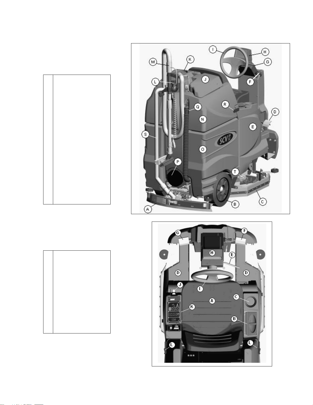
MACHINE COMPONENTS
REAR
Rear squeegee
A
Rear wheel
B
Side squeegee
C
Accelerator pedal
D
Solution tank
E
Steering column pivot
F
Tilt-wheel lever
G
LCD display panel
H
Steering wheel
I
Recovery tank lid
J
Vacuum filter access
K
Vacuum diverter
L
Off-aisle wand
M
Recovery tank
N
Battery compartment
O
Clean-out cap
P
Recovery dump hose
Q
Safety latch
R
Recovery hose
S
Scrub deck
T
MACHINE COMPONENTS
DRIVER’S COMPARTMENT
Operator’s seat
A
Solution tank lid
B
Cup holder
C
Solution tank
D
Tilt-wheel lever
E
Accelerator pedal
F
Parking brake
G
LCD display panel
H
Steering wheel
I
Directional switch
J
Control console
K
Safety latch
L
2
Page 9
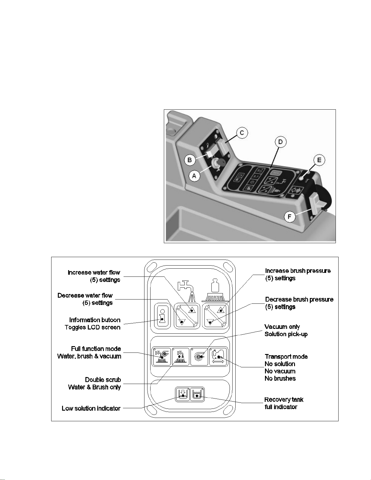
CONTROL CONSOLE
For operator ergonomics, the control console houses all the primary function buttons are grouped in a
central area. The key switch, headlight switch, and off-aisle wand switch are clustered in the back area.
The directional switch (forward and reverse) is located in front of the console for easy fingertip operation.
The horn button, function buttons, and indicators are located in the main central part of the console.
Key switch
(A) Controls the machine’s power (On/Off) with a key for safety. All operational settings are retained even
when the power is turned off and on. This also serves as a reset switch when error or fault codes appear
on the LCD screen.
Off-aisle wand switch
(B) On/Off control for the water supply to
the wand and vacuum motor.
Headlight switch
(C) On/Off control for the headlights.
Main Keyboard
(D) The main keyboard is divided into
three sections: Machine settings,
Machine modes, and tank fluid level
status. See detail descriptions of each
button on the section.
Horn button
(E) Depressing the button will activate the
horn.
Directional switch
(F) When you flip the switch down, the
machine moves forward or flip the switch
upward, the machine will go into reverse
and activate the back-up alarm.
3
Page 10

MAIN KEYBOARD
FULL FUNCTION MODE
When this mode is chosen, a green indicator light will illuminate within the full function icon. When the
machine is running in this mode, all machine functions will be on. When the operator sets the directional
switch to the forward position and steps the accelerator pedal, the solution pump will turn on, the brushes
will turn on and be lowered to the floor, and the rear and side squeegees will be lowered to the floor as the
vacuum motor turns on. While operating in this mode the solution will be dispersed into the brushes, which
will scrub the floor allowing the chemical in the solution to break down the dirt on the floor. As the machine
continues to move forward, the vacuum motor will pull the dirty solution water from the rear squeegee into
the recovery tank. If the operator stops moving forward and switches the directional switch into reverse,
the rear squeegee will rise up (protecting it from damage) and the vacuum motor will turn off after a few
seconds. If the operator stops moving in either direction, the machine will automatically raise and turn off
the brushes, shut-off the water and raise the rear and side squeegees. Some of the functions will take a
little while longer to turn off than others. See the LCD display section in this book to see the image on the
screen looks like when this button is selected.
DOUBLE SCRUB MODE
When this mode is chosen, a green indicator light will illuminate within the double scrub icon. When the
machine is running in this mode, the machine will perform all operations except dirty solution recovery.
This mode can be used if the floor is heavily soiled and the chemical will need additional time to emulsify
grease and oils that are on the floor. When the operator sets the directional switch to either the forward or
reverse position and steps the accelerator pedal, the solution pump will turn on, the brushes will turn on
and be lowered to the floor. While operating in this mode, the solution will be dispersed into the brushes,
which will scrub the floor allowing the chemical in the solution to break down the dirt on the floor. As the
machine continues to move forward or back, the rear squeegee and vacuum system are not on, which
allows the solution to stay on the floor emulsifying the grease and oil. If the operator stops moving in either
direction, the machine will automatically raise and turn off the brushes. After double scrubbing, the
operator should use the vacuum only mode to recover the dirty solution water from the floor. See the LCD
display section in this book to see the image on the screen looks like when this button is selected.
VACUUM ONLY MODE
When this mode is chosen, a green indicator light will illuminate within the vacuum only icon. When the
machine is running in this mode, the machine will only lower the rear squeegee and turn on the vacuum
system to recover the dirty solution from the floor. This mode is usually chosen after double scrubbing to
recover the dirty solution but it can also be used to pick up spills. When the operator sets the directional
switch to forward, the rear squeegee will be lowered to the floor as the vacuum turns on, pulling the dirty
solution water from the rear squeegee into the recovery tank. If the operator stops moving forward and
sets the directional switch to reverse, the rear squeegee will retract (protecting it from damage) and the
vacuum motor will turn off after a few seconds. If the operator quits moving in either direction, the machine
will automatically raise the squeegee and turn off the vacuum motor after a few seconds. See the LCD
display section in this book to see the image on the screen looks like when this button is selected.
TRANSPORT MODE
When this mode is chosen, a green indicator light will illuminate within the transport icon. When the
machine is set in this mode, none of the cleaning functions of the machine will operate. This mode is only
used to transport the machine from one location to another at a faster rate of speed. See the LCD display
section in this book to see the image on the screen looks like when this button is selected.
INFORMATION BUTTON
Depressing the “
hours, and traction motor hours on the LCD display for a few seconds. Keeping this button depressed will
display these items of information for an indefinite amount of time until you release the button. This button
toggles the information on the screen being displayed from machine settings and hour meter information.
See the LCD display section in this book to see the image on the screen looks like when this button is
selected.
i” button will generate specific information such as the machine hour meter, brush motor
4
Page 11
WATER FLOW ADJUSTMENT
These buttons are used to adjust the flow of solution to the brushes. The buttons can be used to select no
flow or one of five solution flow rates where: 1 bar = .25 gpm, 2 bars = .44 gpm, 3 bars = .63 gpm, 4 bars
= .82 gpm, and 5 bars = 1 gpm. Either pressing the increase or decrease flow rate buttons adjusts the
volume of solution flow to the brushes and is displayed on the LCD screen and represents the flow rate
setting selected. The flow adjustments can be made in either the Full function or Double scrub mode. See
the LCD display section in this book to see the image on the screen looks like when this button is selected.
BRUSH PRESSURE ADJUSTMENT
These buttons adjust the brush pressure. The buttons can be used to select one of five brush pressure
settings: 1 bar = lightest, 2 bars = light, 3 bars = medium, 4 bars = heavy, and 5 bars = heaviest. The
pressure is adjusted either by pressing the increase or decrease brush pressure buttons. The number of
bars displayed on the LCD screen represents the brush pressure setting selected. The brush pressure
adjustments can be made in either the Full function or Double scrub mode. See the LCD display section in
this book to see the image on the screen looks like when this button is selected.
EMPTY SOLUTION TANK INDICATOR
The light inside this icon will be illuminated when the solution tank is empty. At the same instant, the LCD
display will have a flashing bar on the solution flow icon signaling the operator of the solution tank status
and the solution pump shuts off. See the LCD display section in this book to see the image on the screen
looks like when this button is selected.
RECOVERY TANK FULL INDICATOR
The light inside this icon will be illuminated when the recovery tank is full. At the same instant, the LCD
display will have a flashing bar on the vacuum system icon signaling the operator of the recovery tank
status. After this warning, the rear squeegee will automatically raise and the vacuum motor will shut off
automatically after a few seconds. See the LCD display section in this book to see the image on the screen
looks like when this button is selected.
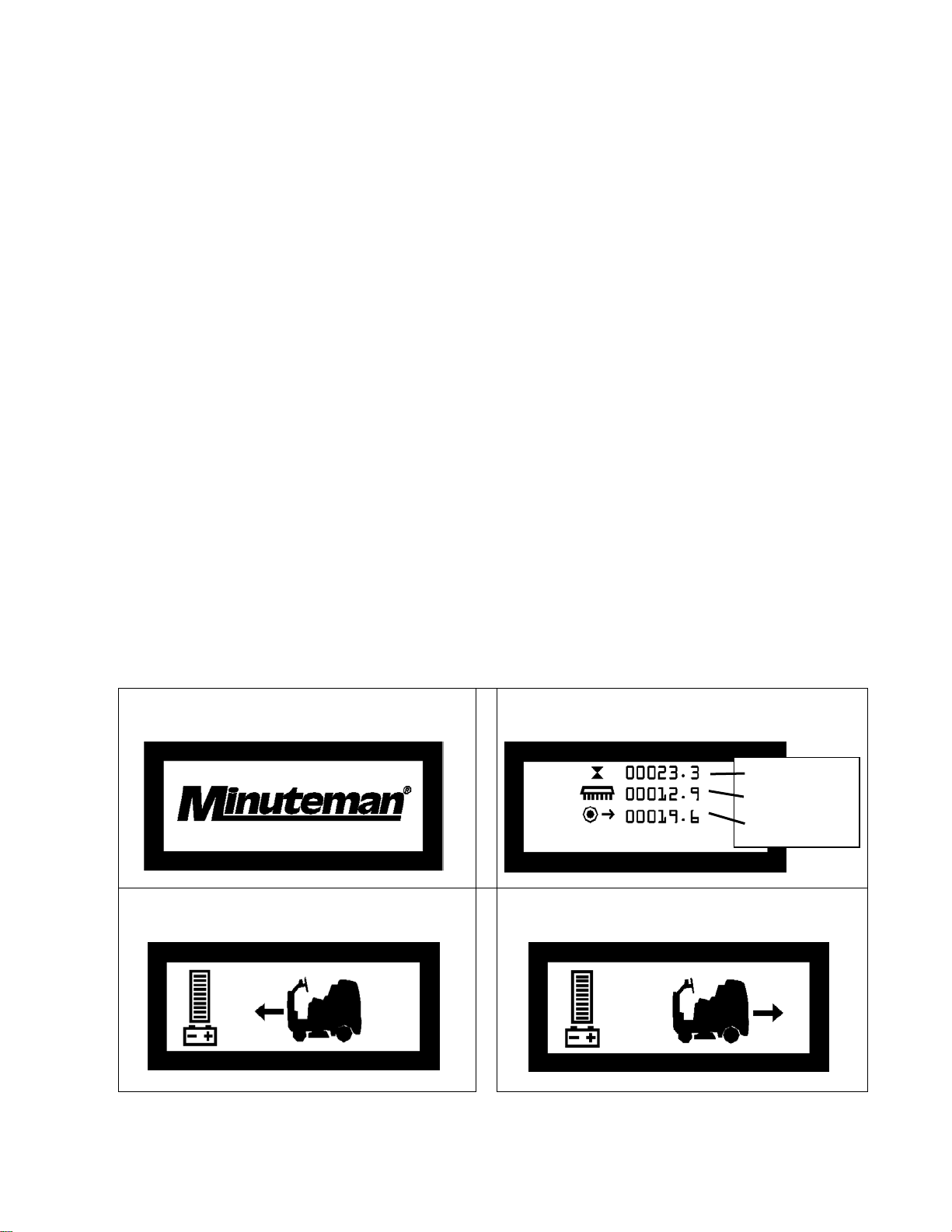
LCD DISPLAYS
The following images below are displayed when selecting the controls or buttons discussed above. The
battery gauge bar will always be displayed whenever the machine is turned on.
KEY SWITCH
When switch is turned on, the Minuteman logo
will appear in the middle of the screen.
INFORMATION BUTTON
Pressing the “i” button will display hours logged on
specific components
Total Hours
Brush Hours
Traction Hours
DIRECTIONAL SWITCH FORWARD
Silhouette of the machine with arrow pointing
forward.
DIRECTIONAL SWITCH REVERSE
Silhouette of the machine with arrow pointing
backward
5
Page 12
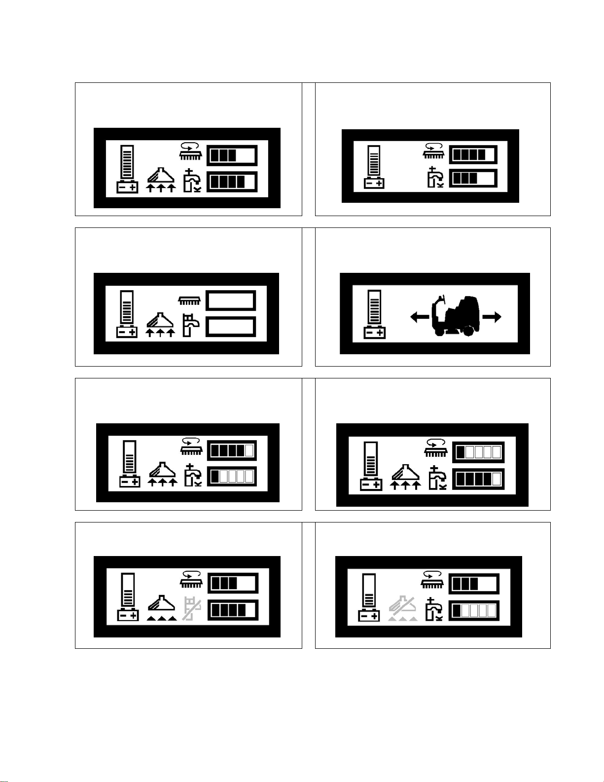
FULL FUNCTION MODE
The vacuum icon with moving arrows, the brush
pressure bars and water flow bars will be
displayed.
DOUBLE SCRUB MODE
The brush pressure bars and water flow bars will
be displayed.
VACUUM ONLY MODE
The vacuum symbol will be displayed and no
bars displayed for brush and flow icons.
BRUSH PRESSURE ADJUSTMENT
Increasing pressure adds more bars to the scale;
decreasing pressure removes bars from the
scale.
TRANSPORT MODE
Silhouette of the machine will be displayed and
arrow pointing to a direction as selected on the
directional switch.
WATER FLOW ADJUSTMENT
Increasing flow adds more bars to scale;
decreasing flow removes bars from scale.
EMPTY SOLUTION TANK INDICATOR
A flashing bar across the water flow icon will be
displayed.
RECOVERY TANK FULL INDICATOR
A flashing bar across the vacuum icon will be
displayed.
6
Page 13
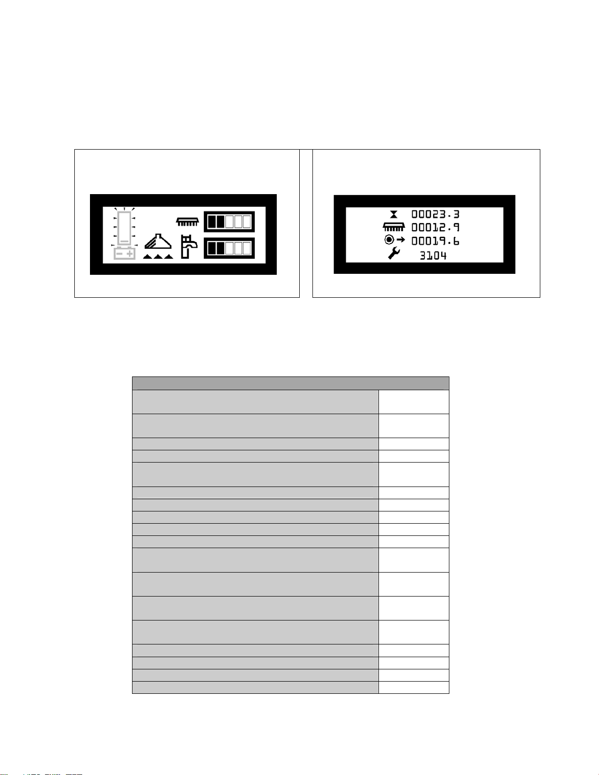
LOW BATTERY INDICATOR
The battery gauge bar icon will be flashing to signal the operator that the machine is almost out of power.
Once this signal is displayed to the operator, all functions will shut off including the transport mode. The
operator has to turn the key switch OFF and then, ON to reset the machine. The machine then will only
have a few minutes left of reserve power for a short Vacuum only mode to pick up remaining solution on
the floor and Transport power.
LOW BATTERY INDICATOR
The battery gauge bar icon will be flashing
indicating that the machine is almost out of
power.
DIAGNOSTIC CODE
At the bottom of the information screen a wrench
symbol with alphanumeric characters will be
displayed when a fault occurs.
FAULT / DIAGNOSTIC CODE
At the bottom of the information screen a wrench symbol with alphanumeric characters will be displayed
when a fault occurs. In most cases, resetting the machine will correct this condition. The operator has to
turn the key switch OFF and then, ON to reset the machine. If this does not work servicing the machine
may be necessary. Below is a list of fault and diagnostic codes for troubleshooting. See Troubleshooting
tips section for further details.
SCV Fault Codes
Switch Reference Codes
May indicate incorrectly wired input switches
Throttle Codes
May indicate incorrectly wired or faulty potentiometer
Power Down Error 0A01 Supply Over Current 1310 Solenoid Brake Codes
May indicate open or short circuit solenoid brake
High Battery Voltage
Throttle Specification Modified
Inhibit Activated
Low Battery Voltage
Battery Lock Out
Throttle Displaced Code
.
.
.
07xx
081x
150x
1600
1D02
1E03
2C0x
2C02
201
May indicate incorrectly wired or faulty potentiometer.
Bridge Supply Faults
May indicate problem with connection of motors
Freewheel Errors
Check condition of freewheel switch and connections
LCD Module Communications Codes
.
.
310x
700x
750x
Serial connections to LCD Module may be intermittent.
Brush Motor Code 760x Vacuum Motor Code 770x Traction Motor Code 780x Emergency Stop or Belly Button Code 790x
7
Page 14
OPERATION OF CONTROLS
POWER SAVE MODE
The SCV is equipped with a power save feature to conserve battery power. If the key switch power is left
ON and none of the controls are activated for a period of fifteen minutes, the SCV automatically goes into
“power down mode” and turns OFF the power to conserve your batteries in case the operator forgets to
turn the key switch off or leaves the machine unattended.
ACCELERATOR PEDAL
Located on the right side of the operator compartment on the floor is the accelerator pedal. This pedal
controls the propelling speed of the machine. The farther the pedal is pushed down the faster the machine
will travel. As discussed earlier, the directional switch governs the direction of travel the machine will take.
Switching the directional switch with your foot pushed on the pedal will make your machine change
directions (a very slight delay may occur before the direction of travel changes when switching directions
on the fly). The accelerator pedal in interlocked with the seat switch, making machine propulsion not
possible without the operator sitting on the seat.
SEAT
The ergonomically designed seat is located on top of the solution tank. There is a lever under the seat that
allows the operator to adjust the seat forward or backward for operator comfort. There is an interlock
switch located inside the seat. This makes it impossible to engage the traction drive circuitry without the
operator on the seat. If the operator were to fall off the machine, the traction drive circuitry would turn off.
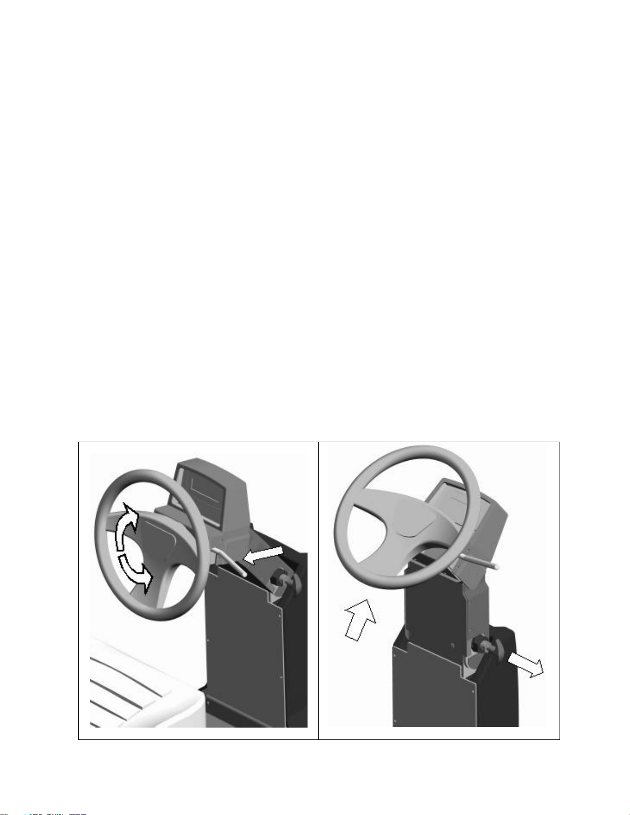
STEERING WHEEL
The steering wheel (FIGURE 1) is adjustable for operator comfort by pulling the tilt-wheel lever back and
positioning the steering wheel up or down (there are four possible positions). Also, a two-position steering
column (FIGURE 2) feature gives the operator easier access to the driver’s compartment when climbing
into and dismounting from the machine. By pulling on the steering column pivot pin and positioning the
steering column in an upright fashion, enables the operator more room when climbing up and down the
machine. The operator can then position the steering column in its normal driving position by returning the
steering column back in its normal position.
FIGURE 1
FIGURE 2
8
Page 15
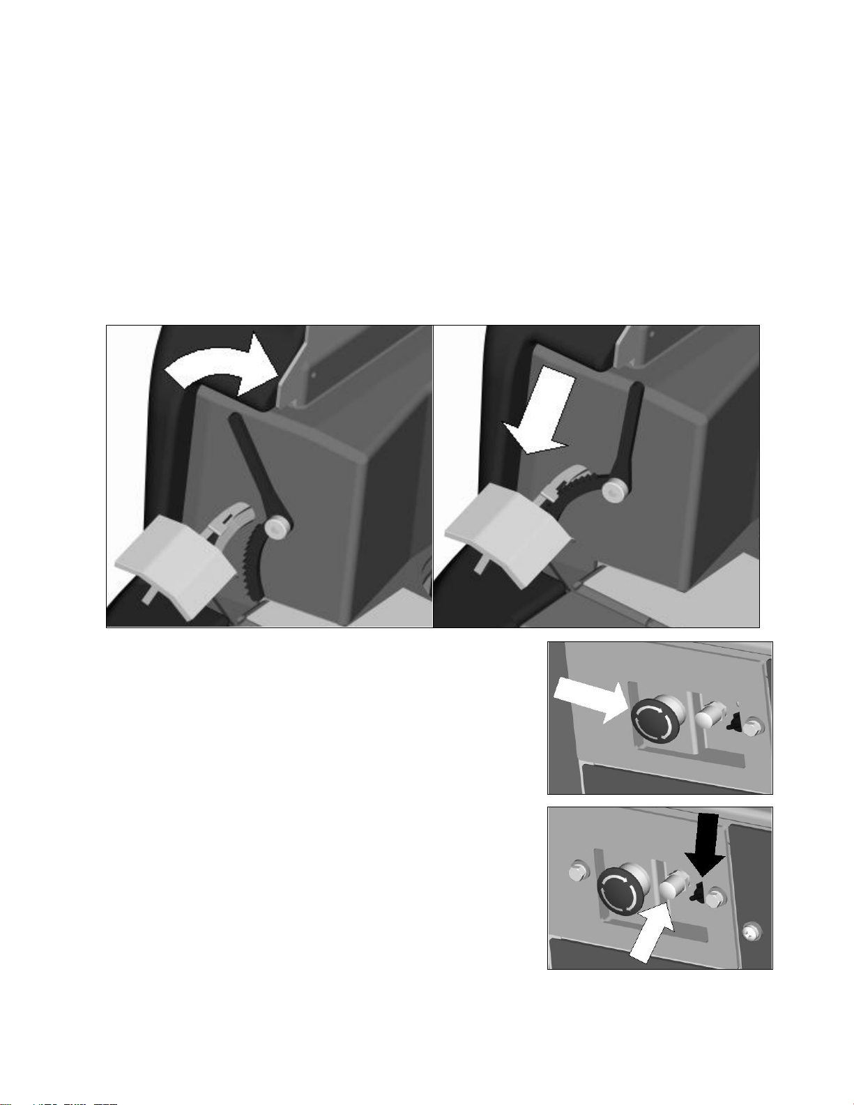
MECHANICAL & PARKING BRAKE
Located on the left side of the operator compartment on the floor is the mechanical brake which doubles as
the parking brake. Even though the machine is equipped with a regenerative braking system, the
mechanical brakes can be activated by pushing down on the pedal and apply brakes on the rear wheels.
The mechanical brake also doubles as a Parking brake. To set the parking brake, press down on the brake
pedal as far down as possible; then, engage the parking brake lever teeth with the brake pedal tab by
rotating the lever clockwise. This will keep the brakes on the rear wheels. To disengage the parking brake,
simply push down on the brake pedal until the parking brake lever disengages itself from the pedal tab.
Another safety feature on the machine is the Electro-magnetic brake built-in on the traction drive motor.
When the machine’s power is turned off (using either the key or the emergency button), the E-mag brake is
activated and the traction motor is prevented from moving.
The mechanical /parking brake system is self-cleaning and periodic use is recommended to avoid
build up of foreign matter that may cause seizing in the mechanism and rust build up.
EMERGENCY DISCONNECT BUTTON
This button is located in the middle of the electrical panel that is
directly underneath the operator’s seat. When the red emergency
button is pressed, power will be turned off. Use this button in case of
a machine emergency. The red knob needs to be raised in order to
run the machine. To reactivate, turn the knob as shown by the arrow
on the switch and the button will pop up. All operational settings are
retained even when the power is turned off and on.
CIRCUIT BREAKERS
The circuit breakers are located next to the emergency disconnect
button. The 6-amp breaker (indicated by white arrow). This breaker
protects all auxiliary circuits on the machine (headlights, horn, and
back-up alarm). The 100-amp breaker (indicated by black arrow)
protects the main system circuit (controller). Each main component is
individually protected with an internal breaker built-in the controller.
(See fault code table) and can be reset by turning the key switch off a
few seconds and then on again.
9
Page 16
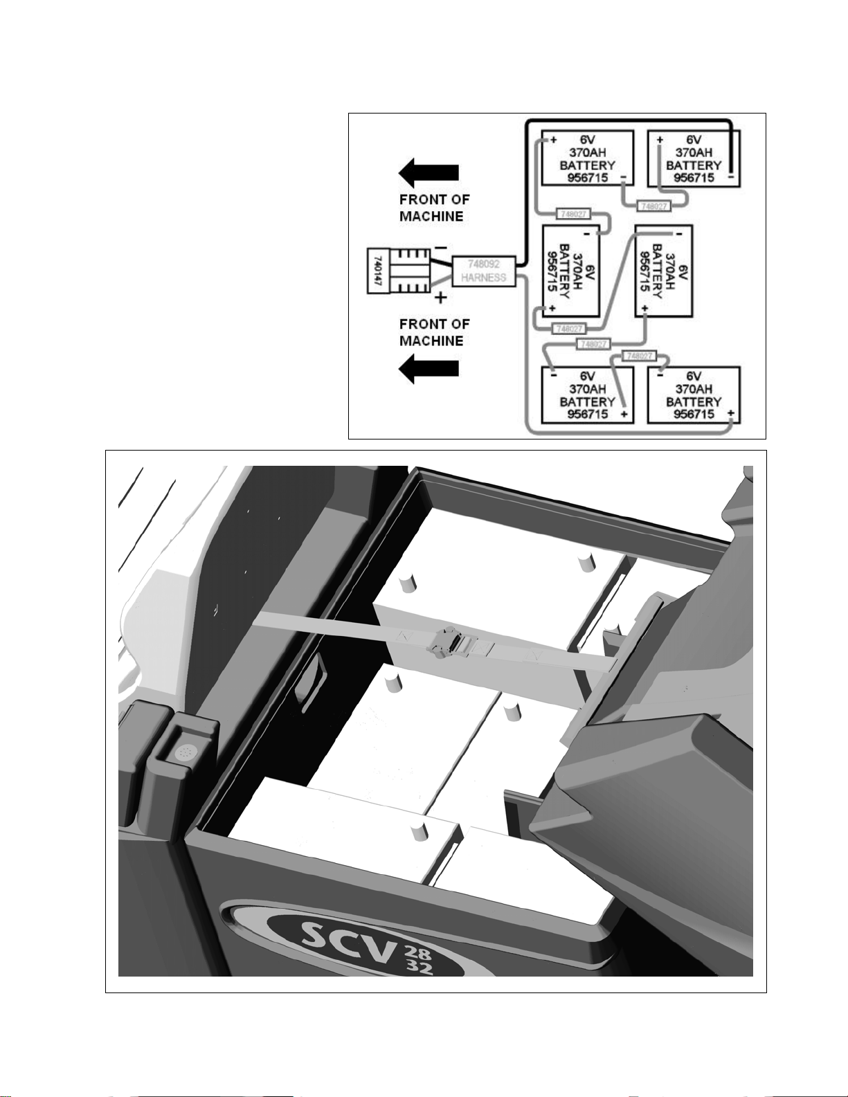
BATTERY COMPARTMENT
The battery compartment is located
on the rear of the machine under the
recovery tank. Unlatching the two
safety latches on the side of the
machine enables the operator to tilt
the recovery tank and access the
batteries for servicing and
maintenance (make sure recovery
tank has been drained before tilting).
The battery compartment contains
six 6-volt batteries connected in
series. Connect the batteries
according to the battery connection
diagram (see diagram). The
recommended batteries are 370Ah
(Minuteman P/N 956715).
10
Page 17
SCRUB DECK
Minuteman offers two deck types (Cylindrical and Disc) to fit your specific needs. The SCV design is very
dynamic wherein the decks are interchangeable in a matter of minutes whenever necessary (removal of
four bolts, and two quick-connects). The cylindrical brush deck has five built-in spray jets to uniformly
dispense cleaning solution on the floor and a wet sweeping debris tray to collect loose objects on the floor.
The disc brush deck dispenses cleaning solution through the center hub and contained within the bristle
area for efficient agitation of cleaning solution to the floor and channeled to the rear of the machine. The
disc brushes are also easily removed and installed with the quick release clamp by using any of the three
access doors. Another nice feature that these scrub decks have is the ability to have uniform brush
pressure applied to the floor at all times. Since the scrub deck brush pressure is computer controlled, it will
automatically adjust and compensate to uneven contours on the floor while maintaining brush pressure.
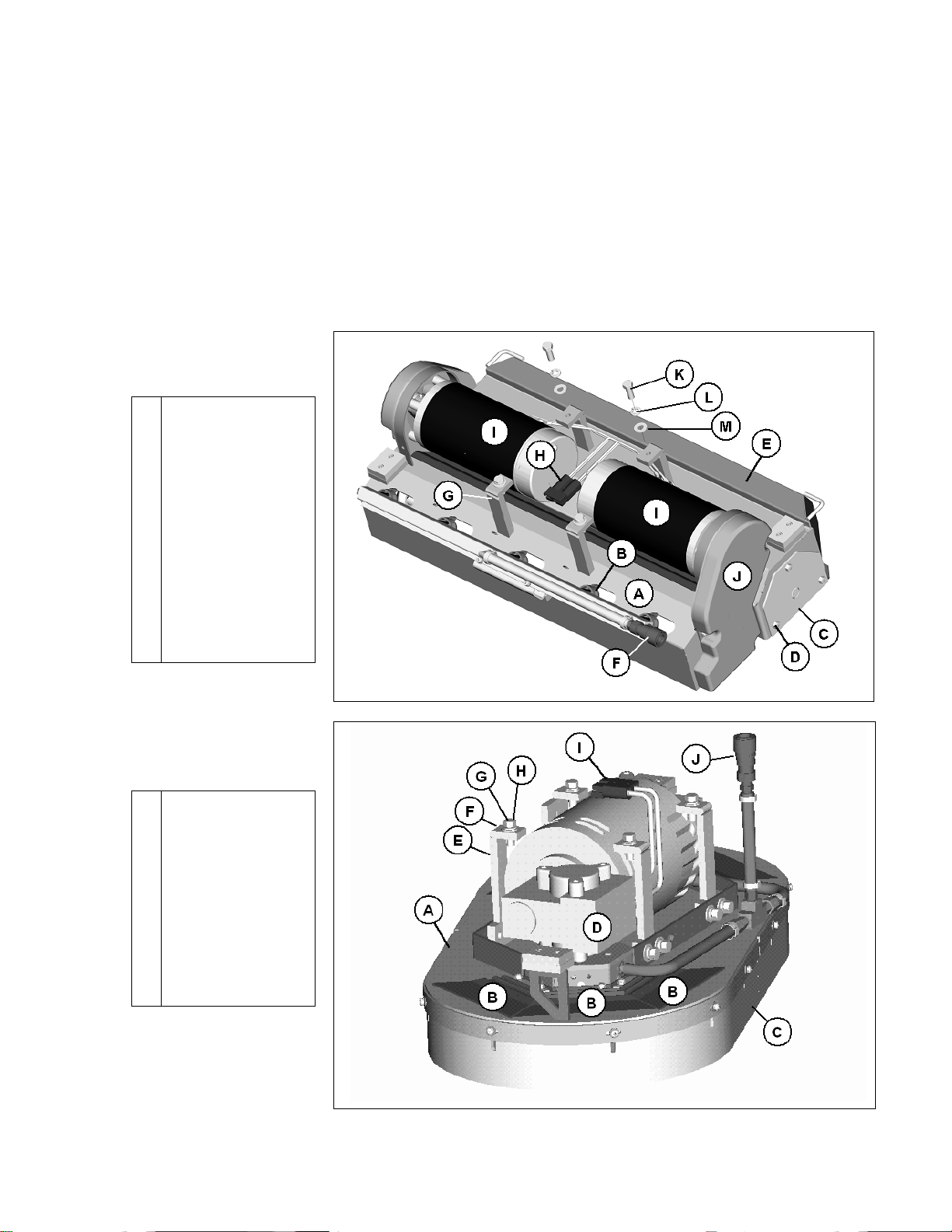
CYLINDRICAL
SCRUB DECK
Housing
A
Spray jets (5)
B
Access door (2)
C
Nut, Access door
D
Debris box
E
Connector, water
F
Mounting bracket
G
Connector, power
H
Brush motor (2)
I
Pulley cover (2)
J
Bolt (4)
K
Lock washer (4)
L
Flat washer (4)
M
DISC SCRUB DECK
Housing
A
Access door (6)
B
Brush skirt
C
Brush motor
D
Mounting bracket
E
Flat washer (4)
F
Lock washer (4)
G
Bolt (4)
H
Connector, power
I
Connector, water
J
11
Page 18
SCRUB DECK INSTALLATION
When installing a cylindrical deck to a machine:
1. Install brushes after the deck has been mounted to avoid flat spots on the brushes.
2. Use a piece of cardboard underneath the deck to prevent scratches to the painted surface when
sliding the deck under the machine.
3. Make sure the scrub deck is oriented correctly with the spray jets towards the front of the machine.
When installing a disc scrub deck to a machine:
4. Install brushes on the scrub deck; this aids the installer in sliding the deck assembly into position.
5. Make sure the scrub deck is oriented correctly with the solution hose tee fitting towards the front of
the machine.
INSTALLATION INSTRUCTIONS
1. Park the machine on a flat or level surface.
2. Activate the parking brake.
3. Remove the 2 screws that fasten each plastic side covers on the machine.
4. Turn the key switch to the ON position and select the transport mode on keyboard.
5. Slide the scrub deck assembly underneath the machine (follow instructions as described above)
6. Position the scrub deck to align the mounting brackets with the mounting lugs on the lift linkage.
7. Lower the lift linkage to the floor by pressing the increase brush pressure button for ten seconds.
(Pressing the up and down brush pressure button for ten seconds toggles the scrub deck
control into a manual up and down mode for the scrub deck linkage).
8. Lower the lift linkage mounting lugs until they barely touch the scrub deck mounting brackets.
9. Fasten with the four (4) 711242 bolts, 711515 flat washer and 711546 lock washer.
10. For cylindrical scrub deck only:
a. Remove the two access doors (one each end) by removing the (3) nyloc nuts.
b. Install the brushes by sliding through the access opening.
c. Align the notches on the brush with the drive pins on the hub.
d. Push brush all the way until it bottoms out.
e. Insert access door hub to the other end of brush.
f. Reinstall nuts and tighten.
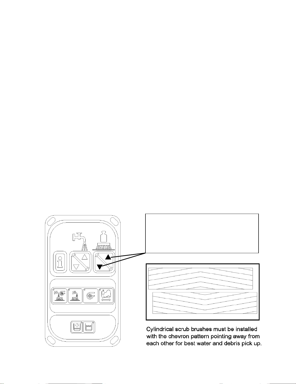
Depressing one of these buttons for ten seconds
will switch you into the manual raise/lower mode.
When you are in this mode, these buttons control
the movement of the lift linkage mechanism. To
get out of this mode, simply reset the machine by
turning the key switch off.
12
Page 19
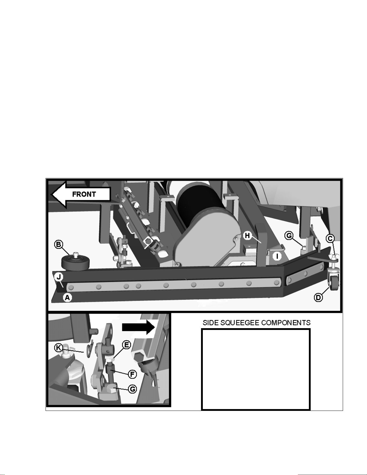
SIDE SQUEEGEE
p
The side squeegees (left and right) are attached to the machine mainframe. These items channel the dirty
solution to the rear squeegee, helping contain the water within the machine’s cleaning path. These
squeegees are raised when the scrub deck is in the raised position. When the scrub deck is deployed, the
side squeegees are also lowered. A lift bracket (item H) raises the side squeegee off the floor when the
machine is in a non-scrubbing mode. The side squeegees are equipped with an adjustable caster (item D)
to control the blade deflection (lowering the caster lessens blade deflection). To adjust the deflection,
loosen the wing jam nut (item C) and turn the caster stem as described below. If the squeegee blade is
deflecting too much, the casters need to be lowered to control the down pressure. Lower the caster by
turning the exposed threaded stem on the caster clockwise. Make the adjustment a few turns at a time. If
the blades are not deflecting enough, raise the caster by turning the stem counter-clockwise to adjust the
caster height to allow more down pressure on the squeegee. A nylon shear bolt (item G) located at the front
and rear of the squeegee prevents undue damage to the assembly in case it hits a solid object. If the side
squeegee is subjected to high impact, the bolt will shear off and prevent severe damage to the assembly. A
turnbuckle adjustment (item F) is provided to adjust the pitch for optimum wiping performance. To adjust,
loosen Lock nut (item E) and turn the turnbuckle to make the necessary adjustments. To clean out the
debris box (item I), set the machine to the double scrub mode and when the scrub deck is lowered to the
floor, turn the key switch off. Slightly lift the debris box up by its handles and slide out towards you.
A. Squeegee blade
B. Roller guide wheel
C. Wing jam nut
D. Swivel caster
E. Lock nut (2)
F. Turnbuckle
G. Shear bolt (2)
H. Lift bracket
I. Debris box
J. Backer strip
K. Cotter
in
13
Page 20
REAR SQUEEGEE
The rear squeegee is the main element that acts as the conduit that transfers the spent solution into the
recovery tank. A daily maintenance check of this component is essential to have optimum machine
performance. The rear squeegee assembly is equipped with a universal front blade that allows the operator
the option to use a slotted and a non-slotted side for specific applications. Each blade configuration has two
usable edges. The rear blade however has four usable edges.
The squeegee is pre-adjusted at the factory. Adjustments may be required to get optimum
performance for different floors and conditions.
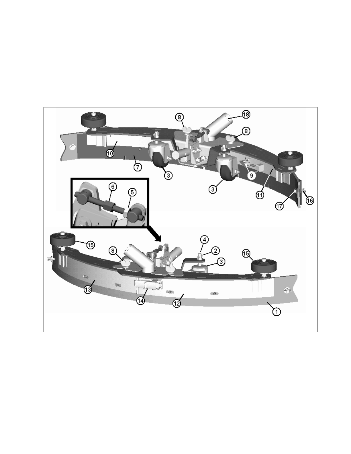
REAR SQUEEGEE COMPONENTS
1. Rear squeegee blade
2. Wing jam nut (2)
3. Caster stem
4. Swivel caster (2)
5. Lock nut
6. Turnbuckle
7. Front squeegee blade
8. Wing bolt (2)
9. Toggle clamp
14
10. Front strap (long)
11. Front strap (short)
12. Rear strap (latch side)
13. Rear strap (catch side)
14. Latch
15. Guide wheels (2)
16. Nylon wing bolt (2)
17. Nylon bolt (2)
18. Recovery hose intake
Page 21
REAR SQUEEGEE ADJUSTMENT
1. Ensure that the scrubber is on a relatively flat surface. Turn on the key switch and select the Vacuum
only mode. This lowers the squeegee to the floor and turns the vacuum motor on.
2. Move the scrubber one or two feet forward slowly while someone behind the machine checks the rear
squeegee blade (item 1) for uniform deflection to the floor.
3. If uneven deflection or lay is evident, minor adjustments may be necessary to avoid streaking and
uneven wear on the blade.
4. To correct this, loosen the wing jam nut (item 2) in order to adjust the caster height. If the squeegee
blade is deflecting too much, the casters (item 3) need to be lowered to control the down pressure.
Lower the caster by turning the exposed threaded stem (item 4) on the caster clockwise. Make the
adjustment a few turns at a time. Repeat step 2.
5. If the blades are not deflecting enough, raise the caster by turning the stem counter-clockwise to
adjust the caster height to allow more down pressure on the squeegee. Repeat step 2.
6. Make sure there is even deflection on the entire length of the rear blade. Adjust the casters and
retighten the wing jam nuts to lock the caster setting in place.
7. Pitch adjustment is necessary if the outer ends on the squeegee blade do not contact the floor and
there is too much deflection in the middle area or if the outer ends are over deflected and there is no
contact in the middle.
8. To adjust the pitch, repeat step 2.
9. Loosen the lock nut (item 5) in the turnbuckle assembly. Turning the turnbuckle (item 6) clockwise or
counter-clockwise controls the forward and backward pitch of the squeegee. Having the rear blades
deflected uniformly along its entire length is the desired set-up.
10. Repeat step 2 until desired set-up is achieved.
11. In certain applications where a non-slotted front wiper blade (item 7) is needed, detach the rear
squeegee assembly by loosening the two wing bolts (item 8). Unlock the toggle clamp (item 9) on the
front squeegee to release the front long strap (10) and slide the front short strap (item 11). Flip the
blade over to the non-slotted side. Reattach the straps and lock the clamp back in place.
12. You can also easily replace the rear blade by unlatching the latch (item 14) and removing the two rear
straps (items 12 & 13) by sliding them off the assembly. You can then flip the blade over in order to
use a new edge for better wiping action.
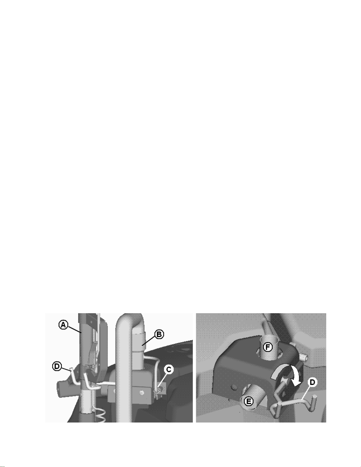
OFF-AISLE WAND
The SCV is equipped with a ready-to-use built-in telescoping off-aisle wand (item A) system for use in hard
to reach areas. This integrated system eliminates attaching hose for use and detaching hoses for storage.
By turning the pump switch ON (located on the control console) and flipping a lever that doubles as the
wand hanger, the off-aisle wand is ready to use in seconds. Flipping the lever up (item D) diverts the
vacuum flow from the main rear squeegee intake (item E) to the off-aisle wand intake (item F). After use,
simply flip the lever back down to its normal position to use as the hand hanger. The wand is also
equipped with the patented flip-flop tool that allows the operator to switch from scrub brush to squeegee
tool by just rotating the tool end.
15
Page 22
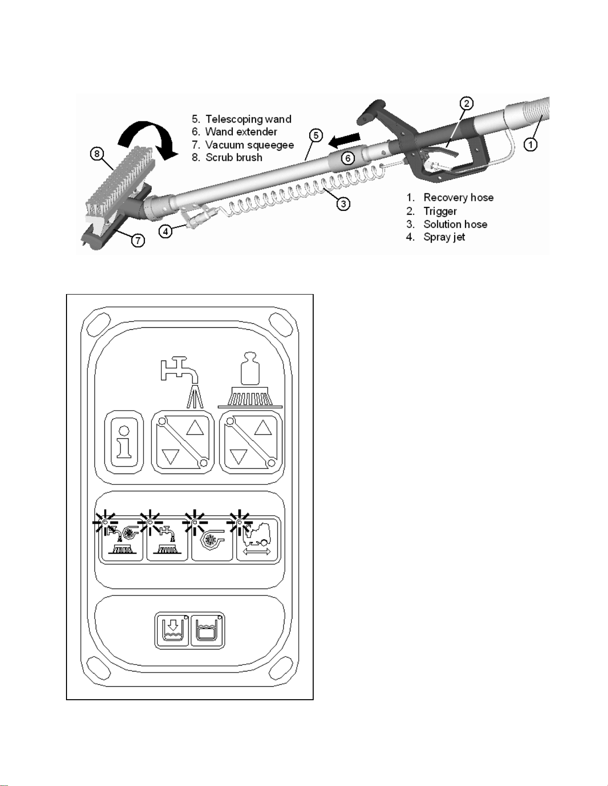
OFF-AISLE WAND TOOL
The off-aisle wand tool as described in the previous page is composed of the following items:
1. The recovery hose is connected to the end of
the wand on one end and to the diverter
assembly (item F) on the other end. This hose
has swivel cuffs on both ends that allow the
operator a good range of motion and the
solution hose to be inside the recovery hose.
2. The trigger controls the solution flow to the
spray jet. Squeezing the trigger opens an
internal valve to dispense cleaning solution.
3. The coiled solution hose acts as a conduit
from the trigger to the spray jet, and allows
hose to be extended along with the wand.
4. The spray jet dispenses the cleaning solution
to soak soiled areas that are not accessible to
the main scrub deck.
5. The telescoping wand allows the length to be
adjusted for operator comfort and better
storage when not in use.
6. Sliding the wand extender forward (as shown
above) extends the wand length during use
and retracts the wand by pulling it back for the
storage position.
7. The flip-flop tool gives the operator complete
flexibility when changing from the scrub
brush mode to vacuum squeegee mode by
simply rotating the end.
When the off-aisle wand switch is turned ON, the
four (full function, double scrub, vacuum only and
transport) mode lights in the keyboard will flash to
indicate that you are in the off-aisle tool mode.
This switch turns on the pump to supply solution to
the wand spray jet and the vacuum motor to
recovery the dirty water. When the recovery tank
is full, the vacuum motor and the solution pump
automatically shuts off.
16
Page 23

THE SCV RIDER
This machine was designed with total operator comfort and ease of use in mind. All machine components
have been designed as a total system to efficiently clean dirty floors. The SCV has four available scrub
head types and sizes to fit specific applications. Please contact your Minuteman representative for specific
recommendations for the correct scrub head type, size, and brush type and chemical applications.
Before using the machine, always perform the following steps to ensure proper machine operation.
• Check under the machine for leaks.
• Check the rear and side squeegees for wear and damage.
• Check the steering for proper operation.
• Check the solution and recovery tanks.
After using the machine, always perform the following steps:
• Check the battery charge level. Charge batteries if necessary. When charging batteries, extra
precaution is required:
Battery acid can cause burns. When working on or around batteries, always wear
protective clothing and safety glasses. Remove metal jewelry. Do not lay tools or metal
objects on top of the batteries.
Charging batteries generate explosive gasses. DO NOT CHARGE BATTERIES WHEN
OPEN FLAMES OR SPARKS ARE PRESENT. DO NOT SMOKE. Make sure the charger
is turned off before disconnecting it from the batteries. Charge the batteries in a wellventilated area. Fluid levels should be checked before and after charging and maintained
at the proper levels. If low, add water until the metal plates are covered. If the machine is
not used for an extended period of time, batteries should be kept fully charged with a
boost charge once a week.
• Check for wire, string, or twine wrapped around the scrub brushes.
• Check the squeegees for wear and damage.
• Check the rear squeegee suction hose and off-aisle wand hose for obstructions.
• Empty and clean the debris box (cylindrical systems only).
• Drain and clean the recovery tank.
• Check under the machine for leaks.
• Check the service records to determine maintenance requirements.
WARNING!
• Be sure you understand the machine controls and their functions.
• While on ramps or inclines, avoid sudden stops when tanks are filled.
• Avoid abrupt sharp turns. Slow down driving speed when going downhill.
• Always drive up when cleaning ramps.
MACHINE OPERATION
Follow the instructions in preparing the machine for use as described in this manual.
1. While seated on the machine, adjust the steering wheel to desired position (for comfort and
unobstructed view of the LCD panel) using the tilt wheel lever.
2. Turn the Key switch ON (I). The LCD panel will light up and display the Minuteman logo for a few
seconds and display the Battery Condition icon and the last functional setting when the machine
was turned off.
3. Release the Parking Brake as described in the Mechanical & Parking Brake section of this manual.
4. Select one of the four available Modes on the Control Console for the required task. Refer to the
Main Keyboard section of this manual for a complete description of the functions.
5. Adjust the Solution Flow and or Brush pressure to desired setting.
6. Determine the direction you need to travel by selecting forward or reverse on the Directional
Switch. The LCD screen will display an icon as described LCD Section in this manual. Vary the
pressure exerted on the accelerator pedal to propel the machine at the desired speed. Stepping on
the accelerator pedal activates.
17
Page 24

7. Stepping on the Accelerator Pedal turns on the Transport, Brushes, Water Flow, Vacuum and
lowers the Rear Squeegee accordingly to the Mode selected. If the operator steps on the
accelerator pedal before, or turns the key switch “ON” at the same time, the machine will not move
as a safety precaution. Simply remove your foot off the pedal and step on the pedal again to drive
the machine. Please refer to the Main Keyboard section of this manual for a complete description of
the functions.
8. When Reverse is selected on the Directional Switch, the Back-up Alarm will be activated and the
Rear Squeegee automatically is raised when you step on the accelerator pedal. However, the
Scrub brushes will continue to rotate and solution will continue to flow.
9. Start scrubbing by driving the machine forward in a straight line at 3/4 speed and overlap each path
by 2 to 3 inches. Adjust your speed; brush pressure and solution flow according to the condition of
the floor.
CAUTION!
To avoid any damage to the floor, keep the machine moving when the brushes are turned on.
10. When scrubbing, check behind the machine occasionally to see that all the dirty water is being
picked up. If streaking occurs, your Water Flow setting may be too high, the Recovery Tank may
be full, the Squeegee hose may be clogged, or the Rear Squeegee may require some adjustment.
11. Make the necessary adjustments on the Rear and Side Squeegees if streaking occurs both in
straight paths and in turns. Pleas refer to the Rear Squeegee and Side Squeegee section of this
manual before making any adjustments.
12. In cases where the floors are extremely soiled and dirty, the Double Scrub mode may be needed.
As described in the Main Keyboard section of this manual, this mode allows the operator to be able
to scrub an area without recovering the cleaning solution with the rear squeegee in the raised
position (no vacuum) to allow the cleaning solution a longer time to loosen dirt. A final pass on the
same area is made with the mode switched over to either Full Function or Vacuum Only mode to
recover the dirty water.
13. The recovery tank has two safeguards for overflow protection to guard against water from entering
the vacuum system when the recovery tank is full. When the indicator light is lit up in the Keyboard,
the Vacuum icon in the LCD Screen will be flashing (see the LCD Display section of this manual).
The vacuum will stay ON for 15 seconds and then shut-off automatically. A ball float shut-off system
has also been integrated into the Recovery Tank. When the dirty water reaches a certain level, the
ball gets suctioned into the vacuum manifold and blocks the airflow thus, preventing the machine
from picking up more liquid. When this happens, the operator is then required to stop scrubbing and
empty the recovery tank.
14. To stop scrubbing, select the Transport mode. This will automatically stop the Solution Flow,
raise the Scrub deck, and raise the Rear squeegee (there is a 15 second delay for the vacuum
motor).
15. Drive the SCV to a designated dirty water disposal area and empty the Recovery tank. To empty,
remove the Drain hose from its storage hanger. Unscrew the plug and hold the hose end above
the water level in the tank to avoid sudden, uncontrolled flow of dirty water. With the plug
completely off, carefully direct the water flow to the desired drain. Reinsert the plug and tighten and
return to its storage hanger.
16. The recovery tank should be rinsed out to remove solids in the tank. Open the Cleanout cap to
remove the Stopper plug. Tilt the recovery tank (similar to accessing the batteries) and clean the
sludge that has settled in the sump area by either back flushing or by scraping it out. Be sure to
tightly secure the Stopper plug and cleanout cap before continuing to operate the scrubber.
17. Refill the solution tank and continue scrubbing until the job is done or when the machine runs out of
power.
18. The battery gauge bar icon will flash to signal the operator that the machine is almost out of
power. Once this signal is displayed to the operator, all functions will shut off (brush will turn off and
the scrub deck will raise up, water flow will cease, the rear squeegee will raise up and the vacuum
motor will turn off) including the transport mode. The operator has to turn the key switch OFF and
then, ON to reset the machine. The machine then will only have a few minutes left of reserve
power for a short Vacuum only mode to pick up remaining solution on the floor and Transport power
to drive to the battery recharging station.
18
Page 25

AFTER USE:
1. When finished scrubbing, select the Transport mode, all functions will shut off (brush will turn off
and the scrub deck will raise up, water flow will cease, the rear squeegee will raise up and the
vacuum motor will turn off). Drive the machine to a service area for daily maintenance and review
items that may need service.
2. Empty the solution tank, by directly opening the Garden hose valve underneath the machine into a
drain on the floor or use a garden and attach it to the fitting to remotely drain the solution tank.
Rinse the tank with clean water to prevent any build-up of dried up chemicals that could cause
clogging in the plumbing.
3. Empty the recovery tank as described on line 15 and 16.
4. Remove the brushes or pad holders and rinse them in warm water and hang to dry.
5. Remove the rear squeegee, rinse with warm water and reinstall after cleaning.
6. Remove the side squeegees, rinse with warm water and remove the debris box (cylindrical
system only) and clean thoroughly. The debris box can be removed from either side of the machine
by tilting the box up and away from the housing and then pulling it out. Reinstall the debris box and
side squeegees after cleaning.
7. Check the maintenance schedule on the next page and perform any required maintenance before
storing the machine.
8. Store the machine indoors in a clean dry place. Keep from freezing. Leave solution and recovery
tank lids open for ventilation to prevent odor build-up.
9. Turn Key switch OFF (O) and remove key.
19
Page 26

MAINTENANCE SCHEDULE
Daily Weekly Monthly Yearly
Charge Batteries
Check/Clean Tanks &
Hoses
Check/Clean/Rotate the
Brushes/Pads
Check/Clean the
Squeegee
Check/Clean Vacuum
Shut-Off Float
Check/Clean the
Vacuum Motor Foam
Filter
Clean Hopper on
Cylindrical System
• Have Minuteman check the vacuum motor carbon motor brushes once a year or after 300
operating hours. The brush motor carbon brushes should be checked every 500 hours or once
a year.
NOTE: Refer to the Service Manual for more detail on maintenance and service repairs.
LUBRICATING THE MACHINE
Regularly scheduled lubrication of certain machine parts should be performed to insure trouble-free
operation of the machine. Apply a generous amount of grease into the fittings on the machine until grease
seeps out around the bearings.
The grease points are listed below:
Rear squeegee caster wheel axle (2)
Rear squeegee caster wheel stem (2)
Side squeegee caster wheel axle (2)
Side squeegee caster wheel stem (2)
Steering wheel chain sprockets and idlers
Apply lubricant or light machine oil to lubricate the:
Rear squeegee general pivot points
Side squeegee general pivot points
Scrub deck linkages
Drive wheel assembly seals.
Check Each Battery
Cell(s) Water Level
Inspect Scrub Housing
Skirts
Inspect and Clean
Solution Filter
Check Foot/Parking
Brake for Wear &
Adjustment
Clean Spray jets on
Cylindrical System
Lubrication – Grease
Fittings, chains, etc.
Check Carbon Brushes
20
Page 27

GENERAL MACHINE TROUBLESHOOTING
Problem Possible Cause Remedy
Poor water pick-up
Poor scrubbing
performance
Inadequate solution flow
or no solution to the floor
No solution to off-aisle
wand spray jet
Machine does not run
No FWD/REV drive
Worn or torn squeegee blades Rotate or replace blades
Squeegee out of adjustment Adjust so blades touch floor
Recovery tank full Empty recovery tank
Recovery tank drain hose leak Secure drain hose cap or replace
Recovery tank lid gasket leak Replace gasket lid cover properly
Debris caught in squeegee Clean squeegee
Vacuum hose clogged Remove debris and flush hose
Using too much solution Adjust solution control valves
Vacuum hose to squeegee or
recovery tank disconnected to
squeegee or damaged
Worn brushes Rotate or replace brushes
Wrong brush or cleaning chemical Consult Minuteman
Debris caught on scrub brushes Remove debris
Moving machine too fast Slow down
Not using enough solution Adjust solution flow setting
Low battery charge Recharge batteries
Fault code on LCD screen 760x
(Brush motor)
Solution tank empty Fill solution tank
Recovery tank full Empty recovery tank
Solution lines, valves, filter or spray
jets clogged
Solution solenoid valve Clean or replace valve
Recovery tank full Empty recovery tank
Solution tank empty Refill solution tank
Emergency stop switch tripped Activate switch by turning as
Operator seat safety switch Operator has to be seated.
Main system controller Check error fault codes
Tripped 100 amp circuit breaker Check for electrical short circuit
Drive system speed controller.
Fault code on LCD screen 780x
(Traction motor)
Emergency stop switch tripped Activate switch by turning as
evenly across entire width
Reconnect or replace squeegee
hose
Reduce scrub brush pressure.
Broken brush drive belts on
cylindrical system, replace belt(s).
Check power connection.
Reconnect plugs.
Reset machine: Turn key switch
off and restart.
Flush lines, and clean solution
filter and spray jets.
indicated by arrows.
Check for open circuit and replace
(See service manual)
Reset machine: Rest breaker and
turn key switch off and restart.
Check error fault codes
(See service manual)
Reset machine: Turn key switch
off and restart.
indicated by arrows.
21
Page 28

Vacuum motor does not
turn on
Poor sweeping
performance (Cylindrical
System)
Solution tank empty
indicator light on
Recovery tank full
indicator light on
Recovery tank full Empty recovery tank
Excessive foaming in recovery tank. Empty recovery tank.
Use less or change chemical.
Use defoaming agent.
Fault code on LCD screen 7700
(Vacuum motor)
Check for motor overload.
Reset machine: Turn key switch
off and restart.
Debris box full Empty and clean debris box
Brushes worn Replace brushes
Bristles have taken a set Rotate brushes
Solution tank empty Refill solution tank
Faulty float switch Replace float switch
Recovery tank. full Empty recovery tank.
Float switch full of debris Clean float switch.
Faulty float switch Replace float switch
22
Page 29

Code Technical
Description
0705 2.5V reference
error
0706 High switch
reference
error
0810
1500
1600 High battery
7500
7600
7601 Brush current
7700 Vacuum motor
7701 Vacuum current
7800
7801 Traction over
Potentiometer
Fault 1
Brake fault 1
voltage
LCD Module
communications
timeout
Brush motor
disconnected
error
foldback
disconnected
error
foldback
Motor fault 1
current error
SCV 28/32 FAULT / DIAGNOSTIC CODES
Probable Cause
All 070x codes – Wiring short
circuit between potentiometer
Hi and Lo reference.
All 081x codes – Throttle wiring
short or open circuits.
All 150x codes – Check brake and
wiring for open or short circuit.
Voltage exceeds maximum.
Wiring fault on 6-way serial link
between SCV and LCD
Open circuit on brush motors or
brush motor wiring.
Brush current overload (“thermal”
trip).
Open circuit on vacuum motors or
vacuum motor wiring.
Vacuum current overload
(“thermal” trip).
Open circuit on traction motor or
traction motor wiring.
Possible short circuit on traction
motor or wiring.
Check for wiring short circuits on the 20way connector on the SCV, the 16-way
connector on the LCD (if used) and the
wiring to the front panel switches &
controls and those switches & controls
themselves.
Check for wiring short circuits or broken wires
on the 20-way connector on the SCV, the 5
way connector on the LCD (if used) and the
wiring to the front panel speed / throttle
control and the speed / throttle control itself.
Check the traction motor connection on the
SCV and check the wiring from this connector
down to the traction motor and checking
connections all the way. Otherwise possible
fault in electro brake on traction motor or
possible controller fault.
Can be caused by poor or corroded
connections to the batteries or a battery
charger being connected.
Check the wiring and connectors on the 6 way
connections on the SCV and LCD.
Check the brush motor connection on the SCV
and check the wiring from this connector down
to the brush motor and checking connections
all the way. Otherwise possible brush motor
fault.
Incorrect programming, incorrectly specified
brush motor, brush motor developing a fault,
excessive resistance on brushes or brushes
pushing down too hard on floor.
Check the vacuum motor connection on the
SCV and check the wiring from this connector
down to the vacuum motor and checking
connections all the way. Otherwise possible
vacuum motor fault.
Incorrect programming, incorrectly specified
vacuum motor, vacuum motor developing a
fault, debris in vacuum motor or airways
blocked by debris.
Check the traction motor connection on the
SCV and check the wiring from this connector
down to the traction motor and checking
connections all the way. Otherwise possible
traction motor fault.
Check the traction motor connection on the
SCV and check the wiring from this connector
down to the traction motor and checking
connections all the way. Otherwise possible
traction motor fault.
Service Action
23
Page 30

7802 Traction motor
in foldback state
7900
2C00 Low battery
2F01
Emergency stop
error
error
Potentiometer
displace error
Traction motor current has
exceeded current limit for the
foldback time.
E-stop input active or wiring fault.
Low voltage warning. Recharge batteries immediately.
Throttle in drive position during
switch on.
Excessive driving up an incline, or machine
driven up against an obstacle or step.
Check for wiring short circuits on the 20-way
connector on the SCV, the 16-way connector
on the LCD (if used) and the wiring to the
emergency stop switch and the emergency
stop switch itself. Otherwise incorrect
operation of machine.
Incorrect operation of machine. Otherwise
check the mechanical condition of the throttle
mechanism. Otherwise check for wiring short
circuits on the 20-way connector on the SCV,
the 16-way connector on the LCD (if used)
and the wiring to the front panel switches &
controls and those switches & controls
themselves.
24
Page 31

25
MAIN ASSEMBLY I
EXPLODED VIEWS
Page 32

26
Page 33

27
MAIN ASSEMBLY II
Page 34

28
Page 35

MAINFRAME ASSEMBLY I
29
Page 36

30
MAINFRAME ASSEMBLY II
Page 37

31
Page 38

FRONT DRIVE ASSEMBLY
32
Page 39

33
Page 40

STEERING ASSEMBLY
34
Page 41

35
Page 42

LCD HOUSING ASSEMBLY
36
Page 43

SOLUTION TANK ASSEMBLY
37
Page 44

38
Page 45

ELECTRICAL PANEL ASSEMBLY
39
Page 46

CONSOLE ASSEMBLY
40
Page 47

RECOVERY TANK ASSEMBLY I
41
Page 48

42
Page 49

RECOVERY TANK II
43
Page 50

DIVERTER ASSEMBLY
44
Page 51

BATTERY BOX ASSEMBLY
45
Page 52

PUMP ASSEMBLY
46
Page 53

47
Page 54

48
REAR AXLE ASSEMBLY
Page 55

SQUEEGEE MECHANISM ASSEMBLY
49
Page 56

50
REAR SQUEEGEE ASSEMBLY 28”
Page 57

51
Page 58

52
REAR SQUEEGEE ASSEMBLY 32”
Page 59

53
Page 60

54
28” CYLINDRICAL SCRUB DECK ASSEMBLY
Page 61

55
Page 62

28” DISC SCRUB DECK ASSEMBLY
56
Page 63

57
Page 64

58
32” CYLINDRICAL SCRUB DECK ASSEMBLY
Page 65

59
Page 66

60
32” DISC SCRUB DECK ASSEMBLY
Page 67

61
Page 68

CYLINDRICAL DECK AND SIDE SQUEEGEE MOUNTING
62
Page 69

63
Page 70

DISC SCRUBDECK AND SIDE SQUEEGEE MOUNTING
64
Page 71

65
Page 72

28” SIDE SQUEEGEE (RIGHT SIDE)
66
Page 73

28” SIDE SQUEEGEE (LEFT SIDE)
67
Page 74

32” SIDE SQUEEGEE (RIGHT SIDE)
68
Page 75

32” SIDE SQUEEGEE (LEFT SIDE)
69
Page 76

70
OFF AISLE WAND ASSEMBLY
Page 77

71
Page 78

PLUMBING DIAGRAM
72
Page 79

POWER WIRING
WIRING DIAGRAMS
73
Page 80

INPUTS TO CONTROLLER
74
Page 81

OUTPUTS FROM CONTROLLER
75
Page 82

KEYBOARD WIRING
76
Page 83

77
MACHINE SCHEMATIC
Page 84

1/03
78
 Loading...