

Page 1

Instruction manual
Port A Scrub with Power Pack
Page 2

Introduction
Preface
Introduction
Dear customer, It is our desire that the
good characteristics of the Port A Scrub
should justify the confidence you demonstrated by making this purchase.
Prior to the first use, read the chapter
"Safety Information” carefully as this will
ensure safe operation of the machine.
Your own safety, as well as the safety of
others, depends to a great extent on
how the machine is moved and operated. Before using the equipment for the
first time, read this original manual thoroughly, act according to the information
contained and keep it in a safe place for
future reference or subsequent owners.
The manual provides valuable information about operation, service and maintenance. The warning symbols as used
in this manual identifies items relevant
to safety. Please observe the safety
provisions (see chapter "Safety Information”). Your authorized Minuteman
dealer will be pleased to answer further
questions regarding the machine or the
operation and maintenance manual.
Please be advised explicitly that we
cannot accept any legal issues out of
the contents of this manual.
If repair work has to be performed make
sure that only genuine spare parts are
used; only genuine spare parts may
guarantee a dependable machine.
We reserve the right for technical improvement.
Valid as of: April 2009
Minuteman International Inc.
14N845 U.S. Route 20
Pingree Grove, II. 60140
U.S.A.
Proper use
The machine is a vacuum scrubbing
machine for wet cleaning of hard-surfaced floors. Using the machine beyond
this scope of application will be deemed
improper use; The manufacturer cannot
be held liable for consequential damages; the user alone bears the risk.
The term of proper use also includes
operation, maintenance and repair work
to be performed in compliance with the
manufacturer's specifications.
The Port A Scrub may only be used by
persons that are familiar with the machine and aware of possible hazards
involved.
If modifications to the machine are
made in absence of the manufacturer's
prior consent, the latter cannot be held
liable for damage resulting from such
unauthorized modification.
2
Page 3

Introduction
Notes on warranty
The terms of the sales contract apply.
Damages are not subject to warranty if
they are due to non-compliance with the
maintenance and service provisions.
The maintenance work has to be performed by an authorized Minuteman
service center and confirmed in the
"Maintenance certificate" which is the
warranty document.
The following is excluded from warranty: fuses, natural wear, damages
caused by overload, inexpert handling
and unauthorized modification of the
Power Pack. Moreover, any claim for
warranty cannot be accepted if damages of the Power Pack are caused by fitting parts or accessories without
Minuteman's prior and explicit consent
or by non-compliance with the maintenance instructions.
Acceptance of the machine
Upon arrival, check machine for possible damages in transit. Follow unpacking
instructions on shipping pallet. Each
unit has been tested and throughly inspected before shipment. Any damage
is the responsibility of the delivery carrier who should be notified immediately.
Minuteman International Inc.
14N845 U.S. Route 20
Pingree Grove, II. 60140
U.S.A.
3
Page 4

Table of contents
Introduction . . . . . . . . . . . . . 2
Preface. . . . . . . . . . . . . . . . . . 2
Proper use . . . . . . . . . . . . . . . 2
Notes on warranty . . . . . . . . . 3
Acceptance of the machine . . 3
1 Safety information . . . . . . . . 5
1.1 Safety and Warning Symbols. 5
1.2 General Provisions. . . . . . . . . 6
1.3 Operating information. . . . . . . 6
1.4 Maintenance information . . . . 7
1.5 Specific Hazards . . . . . . . . . . 8
1.6 Information for Protection of
Environment. . . . . . . . . . . . . . 8
1.7 Labels on the machine. . . . . . 9
2 Starting Up . . . . . . . . . . . . . 11
2.1 Prior to starting up for the first
time . . . . . . . . . . . . . . . . . . . 11
2.2 Before starting up daily . . . . 14
3 Operation . . . . . . . . . . . . . . 15
3.1 Method of operation . . . . . . . 15
3.1.1 Brush head. . . . . . . . . . . . . . 15
3.1.2 Squeegee. . . . . . . . . . . . . . . 15
3.1.3 Solution tank . . . . . . . . . . . . 16
3.1.4 Recovery tank . . . . . . . . . . . 16
3.1.5 Power Pack . . . . . . . . . . . . . 16
3.2 Operating and indicator
elements. . . . . . . . . . . . . . . . 17
3.2.1 Operating panel . . . . . . . . . . 17
3.2.2 Operating elements on the ma-
chine. . . . . . . . . . . . . . . . . . . 19
3.3 Cleaning operation. . . . . . . . 21
3.3.1 After completing cleaning. . . 22
3.3.2 Troubleshooting . . . . . . . . . . 23
3.3.3 Transport and loading . . . . . 23
4 Technical Data . . . . . . . . . . 24
5 Maintenance and Care. . . . 26
5.1 Minuteman System Mainte-
nance . . . . . . . . . . . . . . . . . . 26
5.2 Maintenance Document. . . . 27
5.3 Maintenance plan. . . . . . . . . 28
5.4 Battery system . . . . . . . . . . . 31
5.4.1 Charging batteries . . . . . . . . 31
5.4.2 Attaching the Power Pack . . 32
5.4.3 Detaching the Power Pack. . 32
5.4.4 Servicing the driving
batteries . . . . . . . . . . . . . . . . 33
5.4.5 Removing the batteries . . . . 33
5.4.6 Inserting the batteries. . . . . . 33
5.4.7 Disposing of batteries. . . . . . 33
5.5 Solution tank . . . . . . . . . . . . 34
5.5.1 Filling the solution tank. . . . . 35
5.5.2 Cleaning the solution filter . . 35
5.5.3 Check the seal . . . . . . . . . . . 35
5.6 Recovery tank . . . . . . . . . . . 36
5.6.1 Emptying the recovery tank . 37
5.6.2 Checking the seal. . . . . . . . . 37
5.6.3 Cleaning the air intake filter . 37
5.7 Brush head. . . . . . . . . . . . . . 38
5.7.1 Checking the brush head. . . 39
5.8 Squeegee. . . . . . . . . . . . . . . 40
5.8.1 Cleaning the squeegee . . . . 41
5.8.2 Changing the sealing strips . 41
4
Page 5
Safety information
1 Safety information
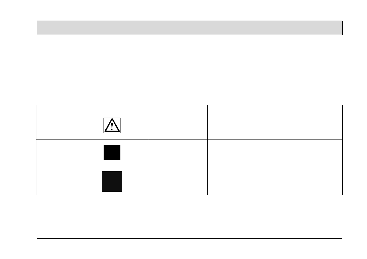
1.1 Safety and Warning Symbols
All paragraphs in this manual referring
to your personal safety, the safety of
your machine and the environment protection are attributed one of the following warning symbols:
Symbol Hazardous for ... Description
Safety Provisions persons and goods Safety Provisions in dangerous situation caused by
misuse inaccurate adherence of instructions or prescribed work routine.
CAUTION the machine important information on handling the machine in
order to maintain operability.
Ecological hazard the environment due to use of substances representing an inherent
danger to health of environment
5
Page 6

Safety information
1.2 General Provisions
• The machine fulfills all the applicable
safety and health requirements stipulated in the EU directives with regard to its planning, constructional
design and final construction as introduced by us onto the market. In
the case of modifications to the machine not approved by us, the EC
Declaration of Conformity enclosed
in this operating manual loses its validity.
• Apart from the provisions contained
in this instruction manual, the general safety provisions and the accident
prevention regulations as impose d
by law have to be complied with.
• Before taking your machine into operation, carefully read the instruction
manual as well as other separate instructions for accessories or attached implements and comply with
all points mentioned there during
work.
• Persons being trained by qualified
Minuteman technicians only are authorised to operate, service and repair the machine.
• You are advised to thoroughly study
the safety instructions since precise
knowledge only helps avoiding errors during operation of the machine
and thus guarantee faultless usage
of the machine.
• The operating instructions have to
be at hand at the place of use of the
machine, and therefore have to be
kept readily available at the machine.
• When selling or letting the machine
for rent, hand out these documents
to the new owner/operator and have
the transfer certified!
• The warning and instruction plates
attached to the machine contain
valuable advice about safe operation. Immediately replace incomplete
or illegible labels.
• As far as safety standards are concerned, spare have to equal genuine
spare parts!
1.3 Operating information
• Before starting the machine up for
the first time, the battery to be used
must be fully charged, properly, by
implementing the initial battery
charge routine. Please pay attention
to the operating manual provided
with the charging unit as well as the
manual from the battery manufacturer. Minuteman assumes no liability
for damage to the battery caused by
a fault when the battery is charged
for the first time.
• Check the operational safety of the
machine each time before starting it
up! Clear any faults immediately! In
the case of function faults in respect
of the charger and damage to the
power cable or battery leads, the
Power Pack must not be put into operation. Please contact your nearest
authorized Minuteman service center.
• Before starting work, the operator
must be fully familiar with all adjustment, operating and control elements as well as their respective
function! It is too late to do this when
the machine is actually in operation!
• Always wear heavy duty, non-slip
footwear when working with the machine.
• The machine may only be driven on
and the equipment used on those
surfaces which have been approved
by the contractor or person appointed by him.
• When using the machine, it is essen-
6
Page 7

Safety information
tial to pay attention to third parties,
especially children.
• Start driving immediately after
switching on the brush drive otherwise imprints of the brush could be
produced on the floor.
• Only use cleaning agents suitable for
the vendor (non-foaming) and observe all the use, disposal and warning information provided by the
cleaning agent manufacturer.
• The machine is not suitable for clearing up hazardous, inflammable or
explosive fluids, dust or substances.
• It is forbidden to use the machine in
potentially explosive atmospheres.
• Directly after beginning a cleaning
operation, check that the waste water is cleared up properly. If a floor
remains wet, it represents an increased risk of slipping!
• To prevent unauthorized use of the
machine, switch off the main switch
and disconnect the battery plug.
• When transporting the machine, tip
the brush head up from the floor with
the shaft.
• The machine has been conceived for
use on level surfaces with a maximum gradient of 2%.
1.4 Maintenance information
• Operating personnel must complete
the necessary daily and weekly
maintenance work. All other maintenance work must be completed at
your nearest Minuteman service
center.
• The maintenance work and maintenance intervals prescribed in the operating manual must be adhered to.
• Suitable tools must be used for
cleaning and maintenance work.
• The machine must be inspected by a
recognized technical expert in respect of operational safety, within
the terms of the applicable accident
prevention laws, at reasonable intervals (we recommend at least once a
year) and following modification or
repairs .
• For reasons of safety, always use
original spare parts.
• When carrying out cleaning and
maintenance work or work on the
electrical installation, always switch
the machine off at the main switch
and disconnect the battery plug and
power plug.
• It is not permitted to clean the machine with a pressure washer or
steam blaster.
• It is not permitted to use aggressive
and corrosive cleaning agents.
• Allow the machine to dry after being
cleaned, e.g. over the weekend.
• Only start the machine up when all
the safety equipment has been installed and brought to its protecting
position.
1.5 Specific Hazards
Electric system
• Only use genuine fuses with the
specified ratings.
• In case of malfunction of the electric
system, immediately shutdown machine and remedy.
• Only qualified personnel are authorized to work on the electrical installations and only according to electrotechnical rules.
• Inspect/check the electrical equipment of the machine at regular intervalls. Clear up any defects
immediately, such as loose connections or damaged cables.
Power Pack
• Observe the information in the operating manual provided by the battery
manufacturer.
7
Page 8

Safety information
• Batteries may only be handled and
changed by properly skilled maintenance personnel.
• The machine has been set up for operation using maintenance-free batteries. It is not permitted to use other
battery types.
• Never lay any metallic objects or
tools on batteries - risk of short circuit!
• Ensure sufficient ventilation in the
charging area when charging the
batteries. – Risk of explosion!
• Ensure that the power cable of the
Power Pack cannot be damaged by
being run over, crushed, tugged etc.
• A charger is installed in the Power
Pack and can be used for operation
via the mains power.
• The Power Pack must be protected
from liquids and damp. It is not permitted to clean the machine with a
pressure washer or steam blaster.
Risk of electric shock!
• There is a risk of tipping when attaching and detaching the Power
Pack. Risk of foot injuries!
• Ensure that the power cable of the
Power Pack cannot be damaged by
being run over, crushed, tugged etc.
The power cable must be checked at
regular intervals for signs of damage
and aging.
1.6 Information for Protection of
Environment
• For safe use of substances inheriting
a danger to health and environment
specific knowledge is required.
• Observe the legal directives and lo-
cal regulations for disposal of detergents, see Water Management Act.
• Used batteries labelled as recyclable
contain reusable economic goods.
According to the crossed dustbin label these batteries must not be added to the normal waste. Provide for
agreement with the Minuteman contract dealer on return and disposal.
8
Page 9
Safety information
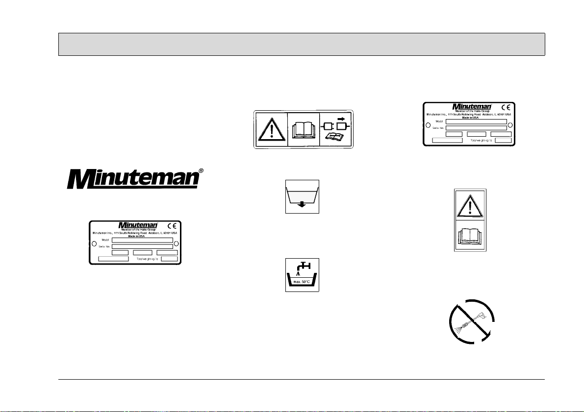
1.7 Labels on the machine
The following safety and warning labels
are attached to the machine where easily legible. Missing or illegible labels
must be replaced immediately.
Port A Scrub
Company logo (Fig. 1/1)
Rating plate (Fig. 1/2)
Machine type (Fig. 1/3)
Port A Scrub
Read and observe the operating manual (Fig. 1/4)
Drain plug for waste water (Fig. 1/5)
Maximum water temperature for the
solution to be filled (Fig. 1/6)
Power Pack
Rating plate (Fig. 1/7)
Read and observe the operating manual (Fig. 1/8)
Do not clean the machine and the Power Pack with a pressure washer (Fig. 1/
9)
9
Page 10
Safety information
2
1
3
4
5
6
9
87
10
Fig.1
Page 11
Starting Up
1
1
2
1
1
3
2Starting Up
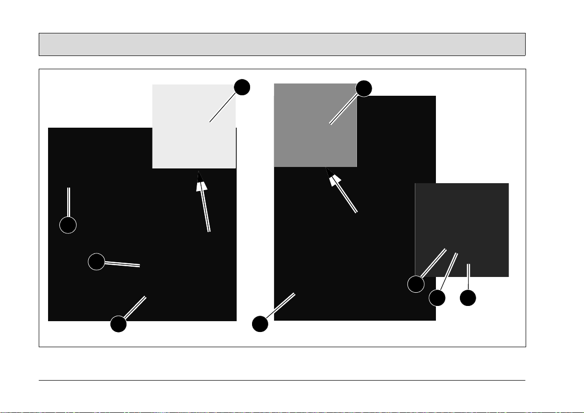
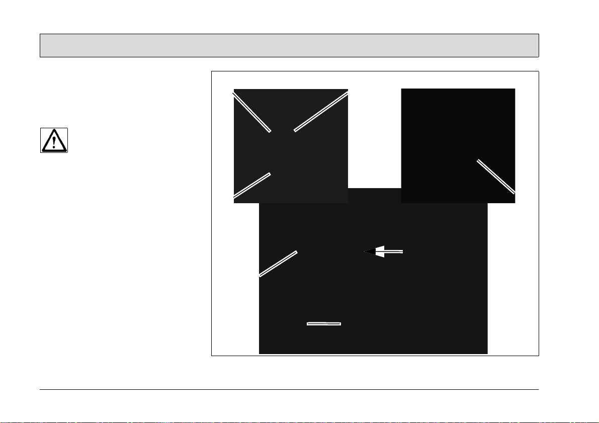
2.1 Prior to starting up for the
first time
1. Open the box containing the Port A
Scrub at the bottom and pull upwards. Loosen the plastic bands and
remove the machine carefully from
the pallet.
2. Remove the insulation blocks (Fig. 2/
1).
3. Loosen the adjusting knob (Fig. 2/2)
and move the steering shaft to its operating position (guide marks facing
each other). Screw the adjusting
knob tight again.
4. Remove the Power Pack (Fig. 2/3)
from the packaging.
Before starting up the equipment for the first time, you
must fully charge the batteries
to be used by completing the
initial battery charge routine
properly, refer to Section 5.4.1.
Minuteman is not deemed liable for damage to the battery
resulting from failure to complete the initial battery charge
properly.
Fig.2
11
Page 12
Starting Up
1
2
3
4
5
6
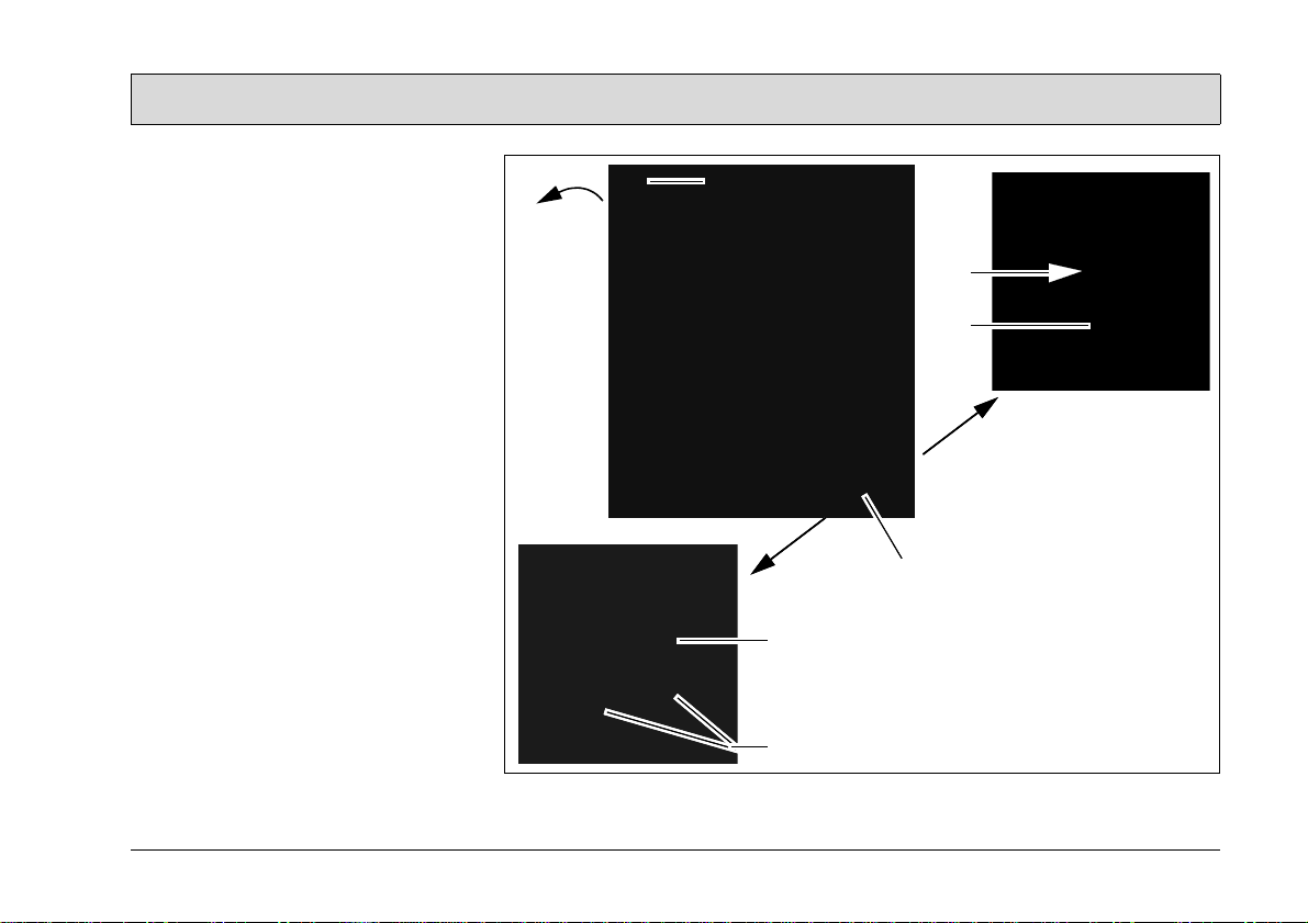
5. Tip the machine back a little using
the shaft (Fig. 3/1) so that it is
against the Power Pack (Fig. 3/2).
6. Slide the bracket (Fig. 3/3) in the
support (Fig. 3/4) of the Power Pack.
Do not hit against the Power
Pack. Risk of tipping!
7. Tip the machine forward again with
the Power Pack attached.
8. Connect the battery plug (Fig. 3/5)
from the Power Pack in the socket
(Fig. 3/6) on the Port A Scrub.
Fig.3
12
Page 13
Starting Up
2
3
X
1
4
5
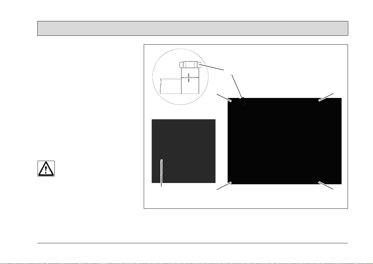
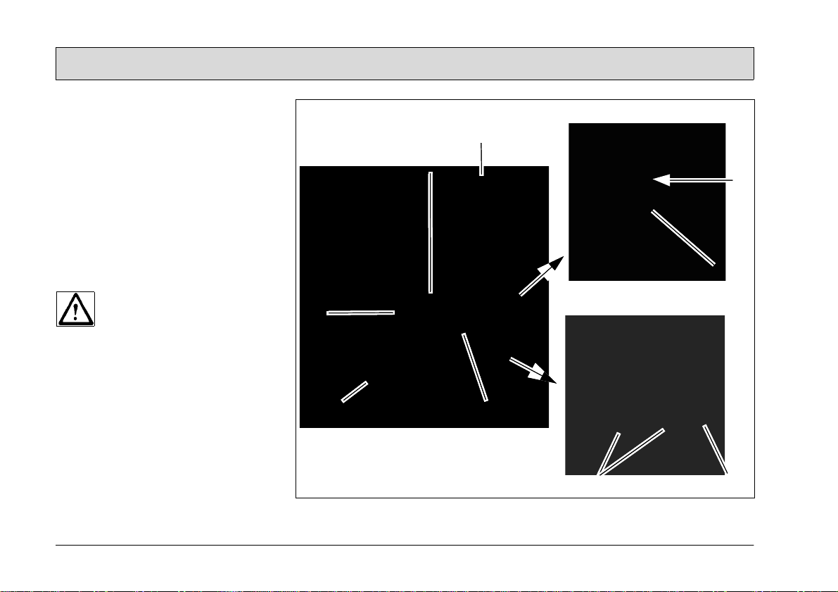
9. Tip the machine a little using the
shaft (Fig. 4/1) until the supporting
rollers (Fig. 4/2) in can be pushed
into parking position (X). Lower the
machine onto the supporting rollers.
10.Loosen the slotted-head screw (Fig.
4/3) with a coin and pivot the cover
(Fig. 4/4) upwards.
11.Insert the brushes (Fig. 4/5) suppli ed
in the brush head, close the cover
and secure it again with the slottedhead screw.
Fig.4
13
Page 14
Starting Up
6
5
7
8
I
X
3
2
4
1
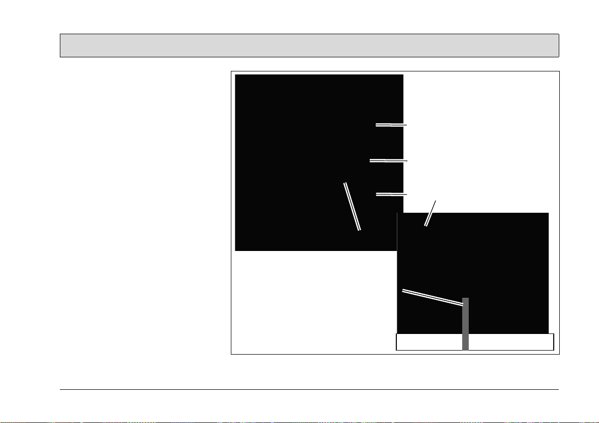
2.2 Before starting up daily
1. Check the following for wear:
- Brushes in the brush head (Fig. 5/
2)
- Sealing strips on the squeegee
(Fig. 5/3)
- Solution filter, air intake filter and
seals in the housing cover (Fig. 5/
4).
2. Check the fill level of the solution
tank (Fig. 5/5), refill as necessary.
Add cleaning agent as necessary,
refer to Section 5.5.1.
3. Check the fill level of the recovery
tank (Fig. 5/6), empty as necessary.
4. Raise the brush head by tipping the
shaft back and slide the supporting
rollers (Fig. 5/8) to the working position (X).
Only use cleaning agents suitable for the vendor (non-foaming) and observe all the use,
disposal and warning information provided by the cleaning
agent manufacturer.
14
Fig.5
Page 15

Operation
1
2
2
3 Operation
3.1 Method of operation
General information
The Port A Scrub is a scrubber drier for
wet cleaning hard floors.
3.1.1 Brush head
The rotating brushes in the brush head
(Fig. 6/1) scrub the dirt free, thoroughly,
with a solution and clean the floor. The
brushes can be disassembled for maintenance purposes.
3.1.2 Squeegee
The moving, suspended squeegee (Fig.
6/2) is adjusted for forward and reverse
operation by means of a hand lever.
The sealing strips on the squeegee
adapt perfectly to the floor. A suction
turbine vacuums up the dirty solution
from the floor.
Fig.6
15
Page 16

Operation
3
1
4
2
3.1.3 Solution tank
The solution tank (Fig. 7/1) for the Port
A Scrub is located under the housing
cover (Fig. 7/2) and has a capacity of
approx. 10 liters. The solution supply is
activated by a button and flows at a rate
of approx. 0.22 liters/min.
3.1.4 Recovery tank
The waste water which is vacuumed up
is fed via a suction hose from the
squeegee to the recovery tank (Fig. 7/
3).
3.1.5 Power Pack
The Power Pack (Fig. 7/4) is equipped
with maintenance-free batteries, a fully
automatic battery charger and a total
discharge signal transducer (TSG) to
protect against total discharge. Pay attention to the safety information with regard to this.
For information on driving batteries, refer to Supplementary Sheet 88-10-
2556.
16
Fig.7
Page 17

Operation
31
5
42
3.2 Operating and indicator
elements
3.2.1 Operating panel
1 Battery indicator
2 Button for water pump
3 Button for suction turbine
4 Button for brush drive
5 Main switch
Fig.8
17
Page 18

Operation
Battery indicator (Fig. 8/1)
This control lamp indicates the charge
status of the batteries.
Button for water pump (Fig. 8/2)
When the brush drive is switched on,
this button is used to switch the water
pump on and off. When the water pump
is switched on, the control lamp lights
up.
Button for suction turbine (Fig. 8/3)
This button is used to switch the suction
turbine motor on and off. When the suction turbine motor is switched on, the
control lamp lights up.
Button for brush drive (Fig. 8/4)
This button is used to switch the brush
drive on and off. When the brush drive
is switched on, the control lamp lights
up.
Main switch (Fig. 8/5)
The machine is ready to operate after
switching on the main switch.
18
Page 19

Operation
1
2
4
5
6
3
3.2.2 Operating elements on the
machine
1 Squeegee adjustment lever
2 Adjustable shaft
3 Bracket for Power Pack
4 Battery plugs, Power Pack
5 Power supply line, charger
6 Charge control indicator
Fig.9
19
Page 20

Operation
Squeegee adjustment lever (Fig. 9/1)
The operator can change the squeegee
position according to the direction of
movement.
Draw lever - reverse operation
Release lever - forward operation
Adjustable shaft (Fig. 9/2)
The shaft must be adjusted to the
height of the operator prior to operation.
To adjust the shaft, release the knob.
Bracket for Power Pack (Fig. 9/3)
In order to be able to start a cleaning
operation, the Power Pack must be
hooked into the bracket on the Port A
Scrub.
Battery plug Power Pack (Fig. 9/4)
The Power Pack battery plug is used to
enable power supply to the Port A
Scrub. When in charging mode, the battery plug must be inserted in the socket
on the Power Pack.
Power supply line, charger (Fig. 9/5)
The power supply line supplies power
to the charger during the charging process. After the charging process has
been completed, the cable must be
wound back in the holder.
Charge control indicator (Fig. 9/6)
The charge control lamp indicates the
status of the charger
• LED (A) lights up yellow = <80%
charge
• LED (B) lights up yellow = >80%
charge
• LED (C) lights up green = 100%
charge
Errors are signaled by the red LED (D).
Contact your authorized Minuteman
service center in the event of an error!
20
Page 21

Operation
31 42
5
6
A
B
A
B
3.3 Cleaning operation
Please read the safety information in
Chapter 1 first and complete the working steps described in Section 2.2.
1. Switch the machine on and ready to
operate using the main switch (Fig.
10/5).
2. Check the battery indicator (Fig. 10/
1), recharge the batteries as necessary; refer to Section 5.4.2.
3. Press the button (Fig. 10/3) to switch
on the suction turbine.
4. Press the button (Fig. 10/2) to switch
on the solution supply (with cleaning
agent, if necessary).
5. Press the button (Fig. 10/4) to switch
on the brushes and move the machine.
- Forward operation (A):
Release lever (Fig. 10/6) and push
the machine.
- Reverse operation (B):
Pull lever (Fig. 10/6) and draw the
machine back.
Fig.10
21
Page 22

Operation
8
7
31 42
5
6
9
10
X
11
3.3.1 After completing cleaning
1. Switch the machine off with the main
switch (Fig. 11/5).
2. Check the battery indicator (Fig. 11/
1), recharge the batteries as necessary; refer to Section 5.4.1.
3. Raise the brush head by tipping the
shaft and slide the supporting rollers
(Fig. 11/6) to the parking position
(X).
4. Transport the machine to an appropriate servicing area.
5. Empty and rinse out the solution tank
(Fig. 11/7) and recovery tank (Fig.
11/8).
6. Clean the machine and check the
following for signs of wear:
- Brushes (Fig. 11/9) in the brush
- Sealing strips (Fig. 11/10) on the
- Solution filter, air intake filter and
Observe the applicable laws
and local regulations when disposing of cleaning agents!
head
squeegee
seals in the housing cover (Fig. 11/
11)
22
Fig.11
Page 23
Operation
5
4
3
2
1
6
3.3.2 Troubleshooting
Following poor cleaning results:
• Check the air intake filter (Fig. 12/1)
for blockages.
• Check the sealing (Fig. 12/2) of the
recovery tank.
• Check the suction hose and squeegee in the brush head (Fig. 12/3) for
blockages.
• Empty the recovery tank (Fig. 12/4).
3.3.3 Transport and loading
1. Detach the Power Pack, refer to
Section 5.4.3.
2. Only transport the Power Pack in a
vertical position, protecting it from
tipping and rolling away.
3. Loosen the adjusting knob (Fig. 12/
5) and move the shaft to its transporting position.
4. Remove the brushes and set the
supporting rollers to their working
position. Lash the machine housing
to the transportation device with appropriate load fixation devices (Fig.
12/6).
Fig.12
23
Page 24

Technical Data
4 Technical Data
Machine length
Machine height inch 21.3
Machine width inch 18.5
Working width inch 17.7
Area coverage, theoretic ft²/h 7534.7
Nominal voltage V24
Power consumption, suction turbine W 370
Power consumption, brush motor W 350
No. of brushes Pieces 2
Brush diameter inch 3.9
Solution tank gallon 2.6
Recovery tank gallon 2.9
Dead weight without Power Pack lb 99.2
Dead weight with Power Pack lb 187.4
inch 31.9
24
Page 25

Technical Data
Noise emission value
The sound pressure level (LpA) (at the ear of the operator) measured according
to DIN IEC 60335-2-72 under normal working conditions: dB (A) 65
Measurement inaccuracy (KpA): dB (A) 2
Vibration
The weighted effective value of acceleration, measured in accordance with DIN
EN ISO 5349, to which the upper parts of the body (hand-arm) are exposed under
normal working conditions:
m/s² < 2.5
25
Page 26

Maintenance and Care
5 Maintenance and Care
General
Before proceeding to maintenance and care work you are
advised to read and comply
with the Safety Information
chapter!
Compliance with the recommended
maintenance works will give you the
certitude of always having a reliable
machine at disposition.
Daily or weekly maintenance and repair
works may be executed by the driver/
operator having been trained accordingly. Further Minuteman system maintenance works have to be executed by
qualified personnel only. Please contact
your local Minuteman Service Centre or
Minuteman contract dealer. We cannot
be held liable for damages resulting
from non-compliance with these instructions.
Please indicate the machine's serial
number with any enquiry or spare part
order, see paragraph 1.7 - Nameplate.
26
5.1 Minuteman System Maintenance
The Minuteman System Maintenance:
• guarantees reliable operability of the
Minuteman machines (preventive
maintenance)
• minimizes operating costs, repair
costs and maintenance costs
• ensures long service life and opera-
bility of the machine
The Minuteman System Maintenance is
structured in separate modules and determines specific technical works to be
executed as well as the intervals for
such maintenance works. For any specific maintenance type, the replacement
parts are determined and listed in spare
part kits.
Minuteman System Maintenance
Customer:
To be performed by the customer in accordance to the maintenance and care
instructions contained in the operating
instructions (daily or weekly). The driver/operator will be instructed upon delivery of the machine.
Minuteman-System Maintenance I:
(six monthly)
To be performed by qualified personnel
of authorised Minuteman Service Cen-
tre in accordance with the machinespecific system maintenance including
spare part kit.
Minuteman-System
Maintenance II/S:
(twelve monthly / safety check)
To be performed by qualified personnel
of authorised Minuteman Service Centre in accordance with the machinespecific system maintenance including
spare part kit. Execution of all safetyrelevant inspections according to UVVBGV-TÜV-VDE as prescribed by law.
Page 27

Maintenance and Care
5.2 Maintenance Document
Handing over
Upgrade
Test drive
Handing over to the customer
carried out on:
System-Maintenance I
six monthly
Workshop stamp
carried out on:
System-Maintenance II
twelve monthly
Workshop stamp
carried out on:
/S
System-Maintenance I
six monthly
Workshop stamp
carried out on:
System-Maintenance II
twelve monthly
Workshop stamp
carried out on:
System-Maintenance II
twelve monthly
Workshop stamp
carried out on:
/S
/S
System-Maintenance I
six monthly
Workshop stamp
carried out on:
System-Maintenance I
six monthly
Workshop stamp
carried out on:
System-Maintenance II
twelve monthly
Workshop stamp
carried out on:
System-Maintenance II
twelve monthly
Workshop stamp
carried out on:
/S
/S
System-Maintenance I
six monthly
Workshop stamp
carried out on:
System-Maintenance I
six monthly
Workshop stamp
carried out on:
27
Page 28

Maintenance and Care
5.3 Maintenance plan
System maintenance, customer
The following maintenance work must
be completed by the customer at the intervals stipulated.
Activity
Check the condition of the power supply line and battery plugs.
Defective cables must be repaired by skilled technicians immediately.
Check the battery charge, recharge as necessary o
Check the filter sieve in the solution tank, clean as necessary o
Empty and clean the recovery tank o
Check the air intake filter in the recovery tank, clean as necessary o
Check the sealing strips on the squeegee, clean or change as necessary o
Check the brushes in the brush head, clean or change as necessary o
Check the seal in the housing cover, clean or change as necessary o
Check the solution feed to the brushes, clean as necessary o
Test drive and function test o
Daily Weekly
o
Interval
28
Page 29

Maintenance and Care
System maintenance I
The following maintenance work must
be completed by an authorized Minuteman service center.
Activity
Interval
Every 6 months
Check the functionality of the operating panel o
Check the seals in the housing cover, change as necessary o
Check the sealing strips on the squeegee, change as necessary o
Check the brushes in the brush head, change as necessary o
Check the solution feed to the brushes, change the nozzles as necessary o
Check the suction hose is fitted properly and for signs of damage, change as
necessary
Check the supporting rollers, change as necessary o
Test drive and function test o
o
29
Page 30

Maintenance and Care
System maintenance II/S (safety
check)
The following maintenance work must
be completed by an authorized Minuteman service center at least once a year.
Activity
All maintenance work in accordance with system maintenance I o
Check the condition of the power supply line and battery plugs, change as
necessary
Check the suction turbine for signs of wear, change as necessary o
Check the water pump in terms of functionality and for signs of wear, change as
necessary
Clean any carbon dust from the suction turbine motor and check the carbon brushes
move easily and for sins of wear, change as necessary
Clean any carbon dust from the brush motor and check the carbon brushes move
easily and for sins of wear, change as necessary
Test drive and function test o
30
Interval
Every 12 months
o
o
o
o
Page 31

Maintenance and Care
1
A
3
2
BCD
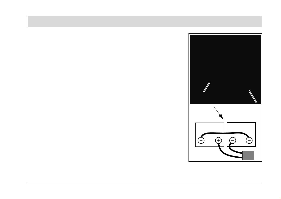
5.4 Battery system
The Power Pack (Fig. 13/1) represents
the power supply for the Port A Scrub.
It is not permitted to clean the
machine with a pressure washer or steam blaster.
Initial battery charge
Before starting the machine up
for the first time, the batteries
to be used must be fully
charged, properly, by implementing the initial battery
charge routine. Minuteman assumes no liability for damage
to the battery caused by a fault
when the battery is charged for
the first time.
5.4.1 Charging batteries
We recommend charging the battery
immediately if the battery indicator (Fig.
14/6) on the Port A Scrub lights up red
during operation. The batteries are
charged using the integrated battery
charger.
1. Connect the battery plug (Fig. 13/3)
to the battery socket on the Power
Pack (as illustrated in the figure).
2. Insert the power plug (Fig. 13/2) in a
mains power socket.
3. The charge status is indicated by
LEDs A to C.
- LED (A) lights up yellow = <80%
charge
- LED (B) lights up yellow = >80%
charge
- LED (C) lights up green = 100%
charge
4. Following the charging process, disconnect the power plug again.
Errors are signaled by the red LED (D).
Contact your authorized Minuteman
service center in the event of an error!
Fig.13
31
Page 32

Maintenance and Care
2
1
3
4
5
5.4.2 Attaching the Power Pack
Please read the safety information in
Chapter 1.
1. Switch off the Port A Scrub using the
main switch (Fig. 14/1).
2. Pull the Port A Scrub against the
Power Pack (Fig. 14/2).
3. Tip the machine to the rear until the
Power Pack can be installed on the
holder (Fig. 14/3).
4. Tip the machine forward again so
that it is horizontal on the floor. The
Power Pack now hangs in the holder.
5. Slide the safety catch (Fig. 14/4) upwards. Plug the battery plug (Fig. 14/
5) in the socket on the Port A Scrub.
5.4.3 Detaching the Power Pack
The Power Pack is detached in the reverse sequence to which it was installed on the Port A Scrub.
32
Fig.14
Page 33
Maintenance and Care
2
5.4.4 Servicing the driving batteries
For information on servicing driving batteries, refer to operating manual 88-60-
2556.
5.4.5 Removing the batteries
1. Park the machine on a level area of
floor.
2. Switch the Port A Scrub off at the
main switch.
3. Disassemble the Power Pack from
the Port A Scrub, refer to Section
2.7.
4. Loosen the four screws (Fig. 15/1)
and lift the cover (Fig. 15/2) off.
5. Remove the battery connection cables.
6. Remove the batteries.
5.4.6 Inserting the batteries
1. Install the batteries in the Power
Pack.
2. Connect the battery poles in accordance with the connection plan (Fig.
15/3) using the connection cables.
Ensure they are connected firmly.
3. Replace the cover (Fig. 15/2) and
secure in place with the screws.
5.4.7 Disposing of batteries
Used batteries with the recycling symbol contain reusable commodities. In
accordance with symbol with the
crossed out bin, these batteries must
not be disposed of in domestic waste.
Return and recycling must be agreed
on with a Minuteman authorized dealer. in
accordance with § 8 BattV (Battery Directive)!
1
3
Fig.15
33
Page 34

Maintenance and Care
1
2
43
5.5 Solution tank
1 Solution tank
2 Solution filter
3Seal
4 Housing cover
34
Fig.16
Page 35

Maintenance and Care
5.5.1 Filling the solution tank
Fill the solution tank (Fig. 16/1) before
starting work or as necessary.
The solution temperature must
not exceed 50 °C!
1. Switch off the machine using the
main switch and disconnect the battery plug.
2. Open the housing cover and remove
the solution tank (Fig. 16/1).
3. Fill fresh water up to the marking, approx. 10 liters (add a cleaning agent
if necessary).
4. Reinstall the solution tank.
Observe the applicable laws
and local regulations when disposing of cleaning agents!
5.5.2 Cleaning the solution filter
Check the solution filter (Fig. 16/2) daily
and clean or change it as necessary.
1. Switch off the machine using the
main switch and disconnect the battery plug.
2. Open the housing cover and disconnect the solution filter (Fig. 16/2)
from the hose.
3. Rinse the solution filter with water or,
if necessary, install a new one.
5.5.3 Check the seal
Check the solution tank seal (Fig. 16/3)
weekly and clean or change as necessary.
1. Switch off the machine using the
main switch and disconnect the battery plug.
2. Open the housing cover and remove
the seal (Fig. 16/3) from the housing
cover.
3. Clean the seal and reinstall it or insert a new one.
35
Page 36

Maintenance and Care
1
2
3
4
5
5.6 Recovery tank
1 Recovery tank
2Drain plug
3Seal
4 Air intake filter
5 Housing cover
36
Fig.17
Page 37

Maintenance and Care
5.6.1 Emptying the recovery tank
Clean the recovery tank (Fig. 17/1) every day or as necessary.
1. Switch off the machine using the
main switch and disconnect the battery plug.
2. Open the housing cover and remove
the recovery tank (Fig. 17/1).
Observe the applicable laws
and local regulations when disposing of cleaning agents!
3. Bring the recovery tank to an applicable disposal point, open the drain
plug (Fig. 17/2) and empty th e recovery tank completely.
4. Flush out the remaining dirt with
fresh water.
5. Replace the drain plug and reinstall
the recovery tank.
5.6.2 Checking the seal
Check the recovery tank seal (Fig. 17/3)
weekly and clean or change as necessary.
1. Switch off the machine using the
main switch and disconnect the battery plug.
2. Open the housing cover and remove
the seal (Fig. 17/3) from the housing
cover.
3. Clean the seal and reinstall it or insert a new one.
5.6.3 Cleaning the air intake filter
Check the function of the air intake filter
(Fig. 17/4) daily and clean it as necessary. The air intake filter can be disassembled by means of a clip
mechanism.
37
Page 38

Maintenance and Care
1
2
3
4
5.7 Brush head
1Brushes
2 Slotted-head screw
3Cover
4 Catches
38
Fig.18
Page 39

Maintenance and Care
5.7.1 Checking the brush head
Check the brush head daily and clean
or change the brushes (Fig. 18/1) as
necessary.
1. Switch off the machine using the
main switch and disconnect the battery plug.
2. Tip the machine a little using the
shaft until the supporting rollers can
be pushed into parking position.
Lower the machine onto the supporting rollers.
3. Loosen the slotted-head screw (Fig.
18/2) with a coin and pivot the cover
(Fig. 18/3) upwards.
4. Remove the brushes (Fig. 18/1) from
the brush head.
5. Install the new brushes and secure
the cover again with the slotted-head
screw.
When installing the brushes,
pay attention that they latch securely and properly in the
catches (Fig. 18/4) provided.
39
Page 40

Maintenance and Care
1
3
4
2
2
3
5
5.8 Squeegee
1 Squeegee
2 Rear sealing strips
3 Front sealing strips
4 Knurled screws
5 Support strip
40
Fig.19
Page 41

Maintenance and Care
5.8.1 Cleaning the squeegee
Check the squeegee (Fig. 18/1) daily
and clean it as necessary .
To clean it, tip the machine to the rear
and lay it carefully on the shaft.
5.8.2 Changing the sealing strips
Check the rear (Fig. 18/2) and front
(Fig. 18/3) sealing strips on the squeegee weekly for signs of wear. The sealing strips can be changed without the
need of tools.
1. Switch off the machine using the
main switch and disconnect the battery plug.
2. Tip the machine to the rear and lay it
carefully on the shaft.
3. Unscrew the knurled screws (Fig.
18/4) and remove the support strips
(Fig. 18/5).
4. Check the rear (Fig. 18/2) and front
(Fig. 18/3) sealing strips, change as
necessary.
The rear sealing strips (Fig. 18/
1) can be turned when worn.
41
Page 42

Excellence Meets Clean
Minuteman International Inc. · 14N845 U.S. Route 20 · Pingree Grove, II. 60140 · U.S.A.
Phone: (630) 627-6900 · Fax (630) 627-1130
988733um REV * 05/09 (Ref.)
 Loading...