

Page 1
Parts & Instruction Manual
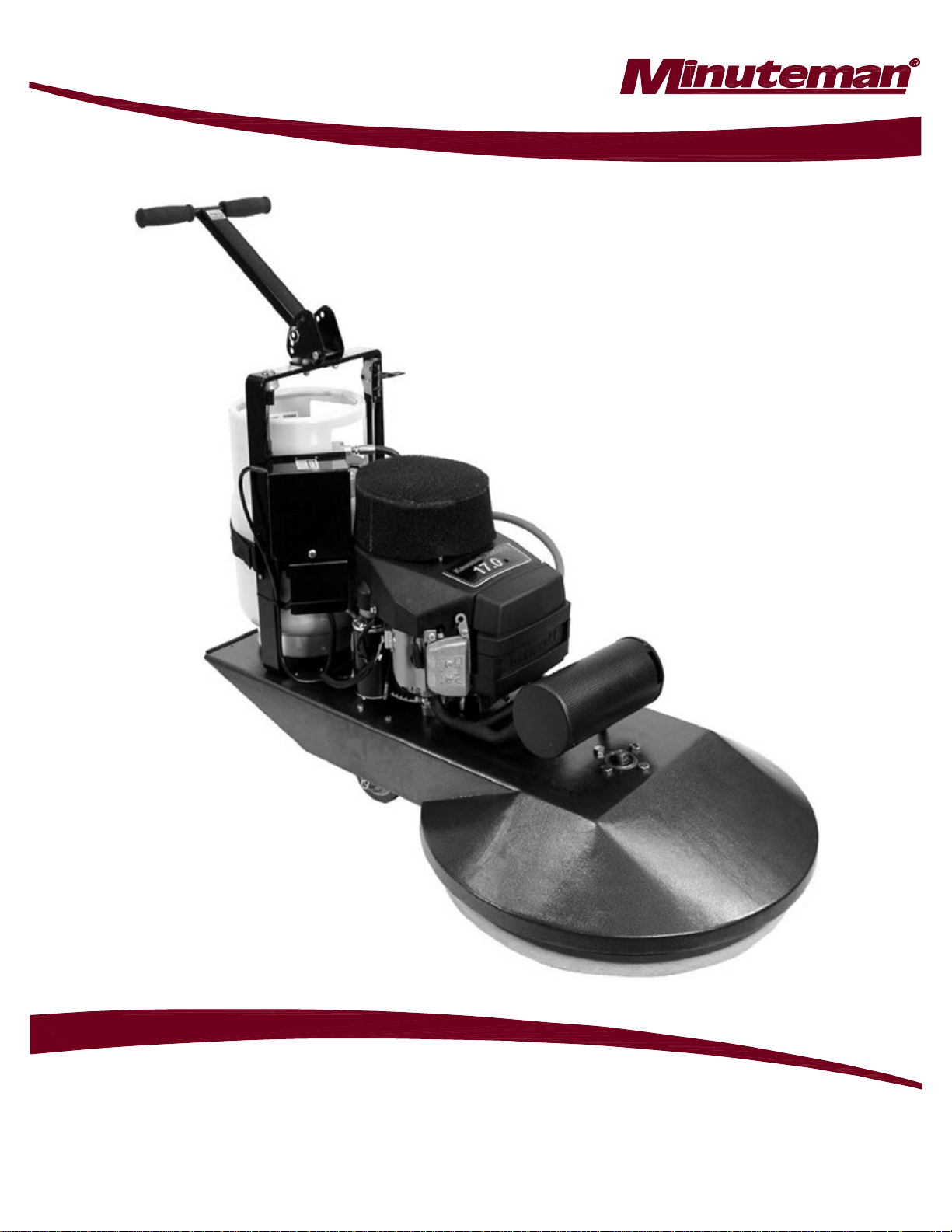
28” Mirage Propane Burnisher - 17 HP Kawasaki
M220028K17A
Page 2

Table of Contents
Safety Instructions ............................................................................................................................. 2
Transport & Preparation..................................................................................................................... 2
Preparation.......................................................................................................................................... 3
Starting the Engine............................................................................................................................. 3
Operation............................................................................................................................................. 4
Stopping the Engine........................................................................................................................... 4
Procedures.......................................................................................................................................... 4
Maintenance........................................................................................................................................ 4
Machine & Engine Maintenance........................................................................................................... 4
Engine Maintenance Meter................................................................................................................... 4
Troubleshooting the electrical system................................................................................................... 4
Kawasaki Engines .............................................................................................................................. 5
Engine Specifications ........................................................................................................................... 5
Belt Inspection & Replacement............................................................................................................. 5
Adjusting Pad Pressure ........................................................................................................................ 5
Oil Change............................................................................................................................................ 6
Engine Maintenance Schedule............................................................................................................. 7
Engine Troubleshooting........................................................................................................................ 7
Replacement Parts ............................................................................................................................. 8
BODY ASSEMBL Y................................................................................................................................ 8
BODY ASSEMBL Y BOM ...................................................................................................................... 9
HANDLE ASSEMBL Y ......................................................................................................................... 10
HANDLE ASSEMBL Y BOM ................................................................................................................ 11
FUEL SYSTEM ASSEMBLY............................................................................................................... 12
KAWASAKI 603cc ENGINE ASSEMBLY............................................................................................ 13
ENGINE BATTERY START WIRING DIAGRAM ................................................................................ 14
Warranty ............................................................................................................................................ 15
Parts And Instruction Manual
28” Mirage Propane Burnisher
Page 3

Parts And Instruction Manual
28” Mirage Propane Burnisher
Page 1
Page 4

IMPORTANT SAFETY INSTRUCTIONS
READ and UNDERSTAND all instructions and
warnings before operating this machine!
!
WARNING
Do not store or use gasoline or other
flammable vapors and liquids in the vicinity
of this machine. Always store equipment
away from heater rooms, boilers, gas-fired
water heaters or any other source of open
flame. Propane is highly flammable.
Always store LPG tanks (full or empty)
outside in a secure, well ventilated area.
NO SMOKING, NO SPARKS, NO FLAMES
NEAR UNIT OR LPG TANK.
Operate only in well ventilated areas. Buildings
must be provided with:
A. A continuous mechanical ventilation that
removes the products of combustion to the
outdoors of not less than 300 CFM for each
10,000 BTUH or fraction thereof; or
B. Natural ventilation of not less than 300 CFM for
each 10,000 BTUH input or fraction thereof,
based on a maximum of one-quarter air
exchange per hour for the net building volume.
If you smell LPG gas, stop the unit and check
for leaks. Also open windows, don’t touch
electrical switches, extinguish any open flames.
Call your gas supplier if no leaks are found.
Do not adjust the fuel system without the proper
analysis equipment.
!
WARNING
Never tilt the equipment on its side for pad, belt
or brush replacement. It is designed to tilt back
on its rear wheel and handle for maintenance
and repair. A second person should aid in
lifting and securing equipment for repair.
Never tilt & transport while engine is running.
Keep hands and feet clear of all moving parts.
Never try to replace parts or repair equipment
with machine running.
T urn the gas off at the tank to kill the engine.
Remove the LPG tank and store it in an
approved area when not in use. A “NO
SMOKING” sign should be permanently
displayed at the storage area.
Always vent an over-full bottle using the tank’s
bleed valve, out of doors away from all closed
places and away from any fire or flame
producing device. Vent until the white vapor
turns clear.
Keep all objects clear of the exhaust system
during and after operation.
Do not leave this machine unattended while
the engine is running.
Do not operate equipment in one location for
more than a few seconds. Damage to floor
surface can occur.
Always store equipment away from possible
damage by falling objects in warehouse-type
areas. Always store LPG tanks outside in a
secure, well-ventilated area.
When the LPG tank is attached to the machine
and not running, the operator should not
leave the machine unattended except for
short periods of time such as rest stops,
washroom or meal stops.
The operator must completely understand all
instructions, warnings and operating
procedures before using this machine.
This machine must be maintained in
accordance with this manual’ s recommended
maintenance instructions and the engine
manufacturer’s recommended maintenance
procedures. Failure to do so may cause
damage to the machine, equipment,
furniture, buildings or personal injury!
A maintenance record should be kept
indicating date of service, hours on engine,
and work done.
TRANSPORT & PREPARATION
!
WARNING
Follow the instructions given in this booklet,
the Engine’s Owners Manual and the
training given by your supervisor for the safe
operation of this machine. Failure to do so
can result in personal injury and/or damage
to the machine or property.
DO NOT OPERATE THIS MACHINE IN AN
EXPLOSIVE ENVIRONMENT!
THIS PROPANE MACHINE IS INTENDED
FOR COMMERCIAL USE.
Parts And Instruction Manual
28” Mirage Propane Burnisher
Page 2
Page 5

Parts And Instruction Manual
28” Mirage Propane Burnisher
Page 3
Page 6

• Propane tanks should be removed &
stored in a protected off site area.
cleaning the unit, check for possible loose nuts
and bolts.
III. OPERATION
Provide and use ear protection during
operation.
Never let an untrained person operate or
perform repairs on the machine. They may hurt
themselves, damage the floor or the
equipment.
Engine speed not to exceed 3400 RPM.
This machine is not suitable for picking up
hazardous dust.
Do not use on surfaces with a gradient
exceeding 2%.
IV. STOPPING THE ENGINE
T urnthe propane tank valve clockwise to a closed
position and turn the key OFF.
NOTE: The exhaust system will be very hot and
takes several minutes to cool, so keep yourself
and all materials clear .
V. PROCEDURES
Follow machine (straight ahead) at moderate
walking speed. Keep moving.
• Do not operate the machine in one location
for more than a few seconds — it will
damage — “burn” the finish.
• When operation is completed remove tank
and store in a secure, protected off site
(preferably outdoor) location.
• Do not use for scrubbing operations.
• Never tilt back machine to maintenance
position while engine is running.
• Never reach under protective shroud when
engine is running.
VI. MAINTENANCE
A. Machine & engine maintenance
1. Refer to engine manufacturer’s owners
manual and comply completely with the
instructions. Change the oil and filter
according to the Engine Owners Manual.
2. Keep a good service log on each machine
with the date, hour meter reading, type(s) of
service performed and the name of the person
who performed them.
3. Clean the entire unit after each use. When
B. Engine maintenance meter
This multi-function meter acts as a preventive
maintenance tool, which benefits you with
increased fuel economy, less down-time and
longer engine life.
The meter’s displays are:
Hour Meter: Displays total run hours when
machine is off.
T achometer: Indicates engine RPM during
operation.
Service Alert: The display flashes to alert you to
lube and change the oil at 25 hour intervals. The
service alert only flashes during operation and it
warns you to change the oil for only two hours.
After the two hours is reached, the alert will
automatically reset to the next 25 hour interval.
Therefore, it is recommended that a separate
maintenance log be kept to track oil changes.
Remember that being safe is a full-time, every
day job. Follow all information posted on the
machine and the LPG tank.
Never allow anyone to operate this machine
who has not read or cannot understand the
given instructions.
C. Troubleshooting the electrical system
1. Check all wire connections for obvious
problems. Remove LPG tank, then remove
battery box cover. Check all connections
visibly and physically. If any “loose”, damaged
or unconnected wires are noticed, replace or
repair as needed.
2. Check the battery posts and wires. Always
wear a face shield, safety glasses and
protective clothing when working around a
battery! The gases can be explosive and the
acid is highly corrosive to metals, cloth and
ALL HUMAN TISSUE (skin, eyes, etc.) If the
battery post(s) are corroded, remove the wires
and clean posts and wires. Applying some axle
grease on the posts of the battery after they are
cleaned will slow down the battery corrosion
process.
If nothing obvious is noted, a more detailed
investigation is warranted. Before any such
troubleshooting begins, the following things
should be done:
a. Replace propane LPG tank with one from
a machine that runs.
Parts And Instruction Manual
28” Mirage Propane Burnisher
Page 4
Page 7

b. Charge the battery or provide an absolute
source of 12 volt DC power capable of 50
amperes total output. (A pair of good
jumper cables from your car or truck
battery will suffice.) Equip yourself with an
inexpensive 12 volt test light.
c. If the trouble seems to be in the electrical
control equipment, you may wish to
disconnect the starter from the system so
as to check the system without spinning
the engine.
d. Battery rundown. A common problem
is letting the battery run down. What
usually happens is that it takes the crew a
few jobs to get used to the whole system,
so the machine is stopped and started
quite often. Key left in on position, when
engine is turned off, will result in battery
running down – dying.
D. Belt Inspection & Replacement
Inspection
• Fold T -Handle to forward position
• Tilt machine back on rear of body & handle
• If belt is worn, cracked or shredding, belt
needs to be replaced.
Replacement
• Place 3/4" wrench on end of the shaft on the
top of the buffer body.
• Turn pad driver counter-clockwise to
remove.
• Take belt off by turning 3/4" wrench on shaft
and removing belt from pad driver pulley
and engine crank pulley.
• Check pad driver pulley & engine crank
pulley for correct alignment.
• Install new belt on engine crank pulley &
pad driver pulley, using 3/4" wrench.
• Install belt on tension pulley
• Install pad drive onto shaft, and return
buffer to operating position.
E. Adjusting Pad Pressure
The pad pressure may be adjusted by moving
the wheels:
• Forward to reduce weight on the buffer pad
or
• Backward to increase the weight
This adjustment may be required to adjust to
different floor finishes or to the weight variance
of aluminum or steel propane tanks.
KAW ASAKI ENGINES
T une-up Specifications
ITEM SPECIFICATIONS
Ignition Timing Unadjustable
Spark Plugs: Champion – RCJ8Y
Gap 0.75 mm (0.30 in)
Low Idle Speed 1500 RPM
High Idle Speed 3400 RPM
Valve Clearance IN: 0.10-0.15 mm
(0.004-0.006 in)
EX: 0.10-0.15 mm
(0.004-0.006 in)
Other No other adjustment
Specifications needed
NOTE: High and low idle speeds may vary
depending on the equipment on which the engine
is used. Refer to the equipment specifications.
Engine Oil
Check the engine oil daily before starting the
engine otherwise shortage of the engine oil may
cause serious damage to the engine such as
seizure.
• Place the engine on a level surface. Clean the
area around the oil gauge before removing it.
• Remove the oil gauge and wipe it with a
clean cloth.
• Pour the oil slowly to “FULL” mark on the oil
gauge.
• Insert the oil gauge into the tube WITHOUT
SCREWING IT IN.
• Remove the oil gauge to check the oil level.
The oil level should be between “ADD” and
“FULL” marks. Do not overfill.
• Install and tighten the oil gauge.
The following engine oils are recommended:
API Service Classification: SF, SG, SH, or SJ.
Oil Viscosity
Choose the viscosity according to the
temperature as follows:
-20˚C -10˚C 0˚C 10˚C 20˚C 30˚C 40˚C
SAE40
SAE30
SAE10W-30/SAE10W-40
SAE5W-20
-4˚F 14˚F 32˚F 50˚F 68˚F 88˚F 104˚F
NOTE: Using multi grade oils (5W-20, 10W-30, and 10W-40)
will increase oil consumption. Check oil level more frequently.
Parts And Instruction Manual
28” Mirage Propane Burnisher
Page 5
Page 8

Parts And Instruction Manual
28” Mirage Propane Burnisher
Page 6
Page 9

KAWASAKI ENGINE MAINTENANCE SCHEDULE
INTERVAL
MAINTENANCE Daily First 8 hr. Every 25 Hr. Every 50 hr. Every 100 hr. Every 200 hr. Every 300 hr.
Check and add engine oil
Check for loose or lost nuts and screws
Check for fuel and oil leakage
Check battery electrolyte level
Check or clean air intake screen
Clean air cleaner foam element
Clean air cleaner paper element
Clean dust and dirt from cylinder and
cylinder head fins
Tighten nuts and screws
Change engine oil
Clean and gap spark plugs
Change oil filter
Replace air cleaner paper element
Clean combustion chambers
Clean and adjust valve clearance
Clean and lap valve seating surface
•
•
•
•
•
•
•
•
•
••
•
•
•
•
•* •
•
*After the 1st 50 hours
ENGINE TROUBLESHOOTING
COMMON PROBLEMS & PROBABLE CAUSES SOLUTIONS
Engine cranks but will not start
• Fuel cylinder is empty Refill cylinder
• Shutoff valve is closed Open valve
• Clogged, obstructed, kinked or cut fuel or vacuum line Remove obstruction or replace line
• Spark plug lead disconnected Connect lead to spark plug
• Faulty choke or throttle settings Set controls to correct positions
• Faulty ignition coil Replace coil
• Faulty kill switch Replace switch
• Faulty regulator Replace regulator
Engine starts hard
• Faulty choke or throttle settings Set controls to correct position
• Clogged, obstructed, kinked or cut fuel or vacuum line Remove obstruction or replace line
• Faulty regulator Replace regulator
• Low compression Valves need adjustment
Engine will not crank
• Battery is discharged Charge or replace battery
• Loose or faulty connections or wires Tighten, repair or replace wires
• Faulty ignition key switch or starter control switch Repair or replace switch(es)
Engine overheats
• Incorrect fuel settings Have engine serviced
• Air intake filter screen or cooling fins clogged Clean and clear debris or replace filter
• Low oil level Check and add oil
Exhaust emissions or propane odor
• Carburetor or regulator setting incorrect Have engine serviced by a trained technician
• Dirty or clogged air filter Replace air filter
• Choke engaged Adjust to correct settings
• Loose fittings, clamps or hoses cracked, hoses cut or leaking Tighten or seal; check with soap and water solution,
Have engine serviced by a trained technician
if bubbles appear, part is still leaking; replace
Parts And Instruction Manual
28” Mirage Propane Burnisher
Page 7
Page 10

Replacement Parts
BODY ASSEMBLY
Parts And Instruction Manual
28” Mirage Propane Burnisher
Page 8
Page 11

BODY ASSEMBL Y BOM
ITEM PART NUMER DESCRIPTION QTY
10 271091 PAD RETAINER (CE NT ER LOK II) 1
11 271094 PAD DRIVE HUB 1
12 271067 WASHER 1
13 271096 PAD DRIVE R 1
14 271095 PAD DRIVE R SUPPORTRI NG 1
15 271007 SPINDLE ASSEMBLY (WITH HUB & BEARINGS) 1
16 271051 BELT 1
17 271097 TENSIONER PULLE Y 1
18 271052 BELT TENSIONER 1
19 271062 HI TCH PIN CLIP 2
20 271060 5" WH EEL 2
21 271061 CLEVIS PIN 2
22 271056 WHEEL BRACKET 2
23 271063 SWIVEL C ASTOR 1
24 271064 NUT 1/ 2-13 X 1 1/2 1
25 271057 BOL T 5/16-18 X 1 1/4 4
26 271054 BOL T 3/8-16 X 2 1
27 271008 BOL T 1/2-13 X 1 4
28 271001 28" ALUMINUM BODY FRAME 1
29 271092 28" MIGHT Y 1
30 271050 SPINDLE PUL LEY (71/2") 1
31 REF ONLY 28" BE IGE PAD 1
PARTS LIST FOR 28" BUFFER BODY ASSEMBLY
Parts And Instruction Manual
28” Mirage Propane Burnisher
Page 9
Page 12

HANDLE ASSEMBLY
Parts And Instruction Manual
28” Mirage Propane Burnisher
Page 10
Page 13

HANDLE ASSEMBLY BOM
ITEM PART NUMBER D ESCRIPTION QTY
1 271033 12V BATTERY 1
2 271029 (+) B ATTERY C A BLE 16.5" 1
3 271032 BATTE RY BOX BOTTOM COV ER 1
4 271099 3/8-16 X 1/2" HEX BOLT 2
5 271026 BATTERY BOX BRACKET 1
6 271038 STARTE R SOL ENOID 1
7 271085 VELCRO TANK STRAP 1
8 271093 TANK STRAP BRACKET LOOP 2
10 271012 1/4-20 X 1 1/2" HEX BOLT 1
11 271011 THROTTLE CABLE 1
12 271076 20LB. LPG CYLINDER 1
13 271101 HANDLE GRIP 2
14 271074 3/8-16 X3" HEX BOLT 1
15 271080 LOCK PIN 1
16 271071 LEFT HANDLE BRACKET 1
17 271070 T-HANDLE 1
18 271072 RIGHT HANDLE BRACKET 1
19 271073 3/8-16 X 1" HEX BOLT 4
20 271002 HANDLE MAINFRAME 1
21 271100 3/8-16 STOVER LOK NUT 7
22 271031 BATTERY BOX TOP COVER 1
23 271030 (-) BATTERY CABLE 26" 1
24 271024 KEYSWITCH 1
25 271025 WIRE HARNESS 1
26 271013 1/4-20 FLANGE NUT 1
PARTS LIST FO R BUFFER HANDLE ASSEMBLY
Parts And Instruction Manual
28” Mirage Propane Burnisher
Page 11
Page 14

FUEL SYSTEM ASSEMBLY
ITEM PART NUMBER DESCRIPTION QTY
1 271043 QUICKCOUPLER 1
2 271042 LPG HOSE 14" 1
8 271044 FUEL HOSE FITTING 1
9 271041 FUEL LOK- OUT (12VOLT) 1
10 271040 FUEL REGULATOR( T60-E) 1
Parts And Instruction Manual
28” Mirage Propane Burnisher
PARTS LIST FOR BUFFER FUEL SYSTEM
Page 12
Page 15
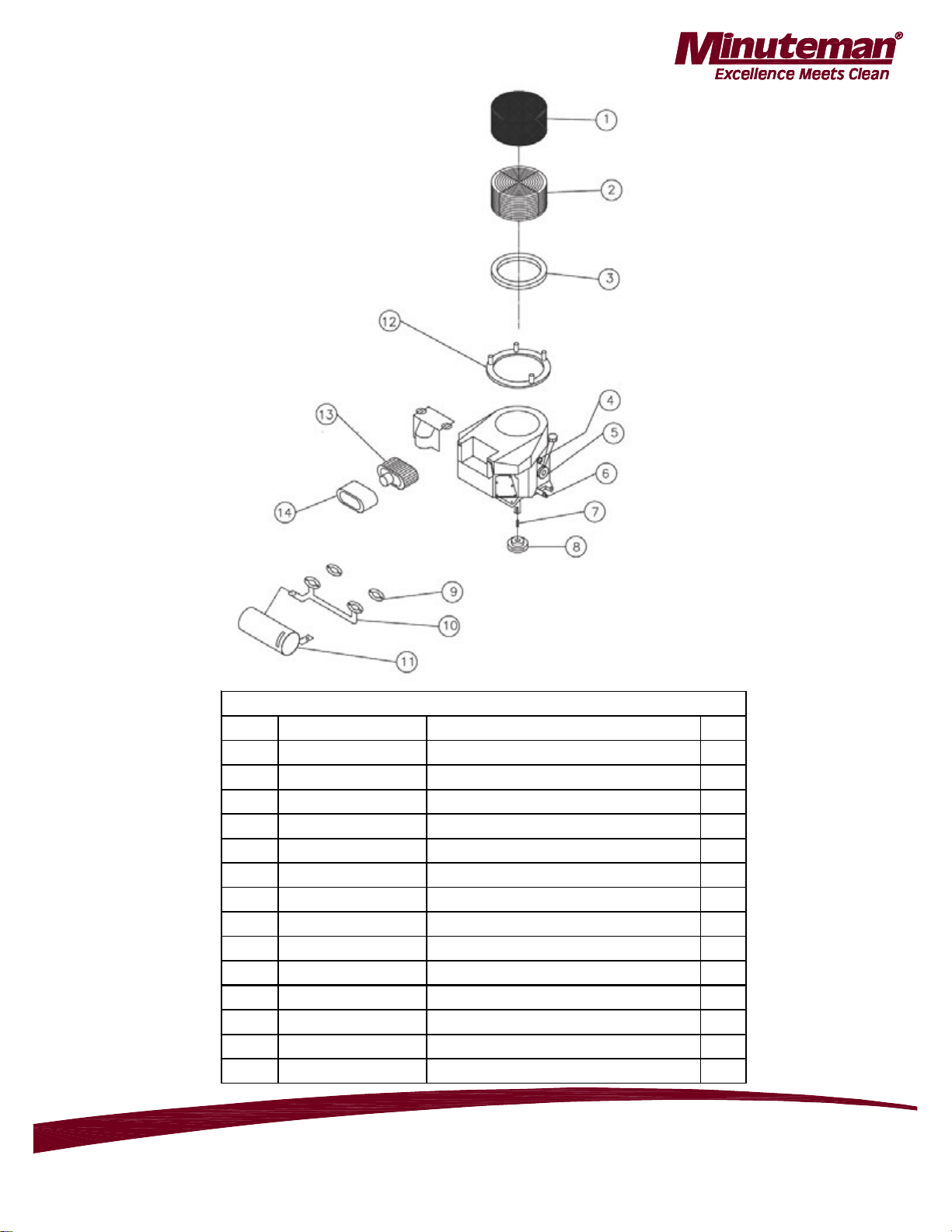
KAWASAKI 603cc ENGINE ASSEMBLY
KAWASAKI 60 3cc ENGINE
ITEM PART NUMBER DESCR IPTIO N QTY
1 271086 FOAM HAT FILTER 1
2 271103 DEBRIS SCREEN 1
3 271104 FOAM HAT SEAL 1
4 271098 OIL PRESSURE SWITCH 1
5 271132 OIL FILT ER 1
6 271088 OIL DRA IN VALV E 1
7 271048 1 / 4 X 1 1 / 4 KEY 1
8 271049 CRANK PULLEY 1
9 271133 EXHAUST MANIFOLD G ASKET 2
10 271134 EX HAUST M ANIFOLD 1
11 271135 CATAL YTIC MUFFLER 1
12 271136 DEBRIS SCREEN ADAPTER 1
13 271137 AIR FILT ER ELE M ENT 1
14 271138 FOAM PRE FILTER 1
Parts And Instruction Manual
28” Mirage Propane Burnisher
Page 13
Page 16

ENGINE BATTERY START WIRING DIAGRAM
Parts And Instruction Manual
28” Mirage Propane Burnisher
Page 14
Page 17

Minuteman International Made Simple Commercial Limited Warranty
r
r
A
r
REVISION E
Minuteman International, Inc. warrants to the original purchaser/user that the product is free from defects in
workmanship and materials under normal use. Minuteman will, at its option, repair or replace without charge, parts
th at fa il un der no rmal use an d servi ce whe n oper ate d and m aintai ned in acco rdanc e with the ap pli cable o perat ion
and instruction manuals. All warranty claims must be submitted through and ap proved by factory aut horized repai
stations.
This warranty does no t apply to normal wear , or t o items whose life is depende nt on their use and care, such as be lts,
cords , sw it c hes, hose s, rub ber part s, electrical motor components or adjustments. Part s manu factured by Minuteman
are cover ed by and su bject to the w ar r anties and/or guarant ees of the ir manuf acturers. Please contact Minut eman fo
pro cedures in warranty claims again st t hese manu fact ur ers.
Spe c ial wa rning to pu rc h a se r -- Use of replacement filters and/or prefilters not manufactured by Min uteman or its
designated licensees, will void all warranties expressed or implie d. A potential health hazard exists w ithout original
equipmen t repla cement.
ll warranted items become the sole property of Minuteman or its original manufacturer, whichever the case may be.
Minuteman disclaims any implied warranty, including the warranty of merchantability and the warranty of fitness for a
par ti cula r purpose . Minuteman assumes no responsi bility for any special, inc idental or consequential dam ages.
Th is limited warr a nt y is ap pl i ca ble on ly in the U. S. A. an d Can a da , an d is ex te nd e d on l y to t he ori gi n al use r /p ur ch as e
of this product. Customers outside the U.S.A. and Canada should contact their local distributor for export warranty
policies. Minuteman is not responsible for cos ts or repairs performed by persons other than those specifi cally
authorized by Minuteman. This warranty does not apply to damage from transportation, alterations by unauthorized
persons, misuse or abuse of the equipment, use of non-compatible chemicals, or damage to property, or loss of
inc ome d ue t o malfu nctio ns of th e product .
If a difficulty de velops with this machi ne, you should co ntact th e dealer from who m it was purchas ed.
This warranty gives you specific legal rights, and you may have other rights which vary from st ate to state. Some
states do not allow the exclusion or limitation of special, incidental or consequential damages, or limitations on how
long an implied war r ant y lasts, so the ab ove exclusions and li mi tations may no t appl y to you.
Cord Electri c Group………. T hree years par ts, two ye ar s labor, nin et y days trave l (Not t o exceed two hours)
Exceptions………. Port-A-Scrub, one year parts, six months labor
X12 and X12H, one year parts, one year labor
TRS 14, one year parts, one year labor
E17/E20 electric scrubbers, one year parts, six months labor
Battery Operated Group….. Three years pa rts, two years labor, ninet y days t r avel
Exceptions……Sweepe r s , o ne yea r parts, one year labor , ni net y days travel
Internal Combustion Group….One year parts, one year labor, ninety day travel
Exceptions………..Mira ge pr opane burnishe r, o ne year p arts, o ne ye a r labor
Battery Chargers
………………. ..One year replacement
Replacement Parts……………..
Batteries………………………….0-3 months replacement, 4-12 months pro-rate
Polypropylene Plastic Tanks…Te n years, no a dditional labo r
14N845 U.S. Route 20 Pingre e grove, I L 60140
EFFECTIV E 1/ 1 /2009
MPV 13, one year parts
V Series Upright Vacuums, One year parts, one year labor
MPV 14 and 18, two year s parts, one y e ar labor
Ra pi dAir bl ow er, one ye ar pa r ts , on e yea r labo r
Explosion-Proof Vacuum, one year parts, one year labor
(Not to exceed two hours)
(Not to exceed two hours)
(Not to exceed two hours)
Ninety days
Phone: 800-237-3192
E-M ail: www. minu temanintl.c om
999378
Rev C 08/11
 Loading...