

Minuteman MCP 10001, MCP 6001 User Manual

Continuous Power Series
User ’s Manual
MCP 6001
MCP 10001

TABLE OF CONTENTS
1. INTRODUCTION 1
1.1 Explanation of symbols 1
1.2 System description 1
1.3 Product specification 2
Electrical specifications 2
Operating environment 2
Mechanical specification 2
1.4 Switches and displays 3
1.5 Safety 4
1.6 Communication port 6
1.7 RS232 interface 6
2. INSTALLA TION AND OPERA TION 6
2.1 Unpacking and inspection 6
2.2 Installation 6
2.3 Wiring description 7
3. TROUBLESHOOTING 10
APPLICA TION NOTES A1
1. ST ART UP A1
2. OUTPUT VOL TAGE SETTING A2
3. DISPLA YS AND ALARMS A2
1. Load level and battery capacity A2
2. Alarm for inverter short-circuiting and output overvoltage A2
3. Alarm for bus overvoltage A2
4. Alarm for over-temperature A3
5. Display and alarm for overload A3
6. Alarm for BATTERY WEAK or BATTERY BAD A3
7. Alarm for abnormal input voltage A4
8. Battery over-voltage alarm A4
9. Bypass S.T.S short alarm A4
10. Inverter S.T.S short alarm A5
4. LIMITED PRODUCT WARRANTY A5
5. DECLARA TION OF CONFORMITY A6
1. INTRODUCTION
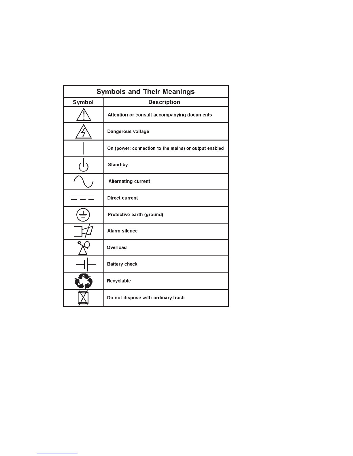
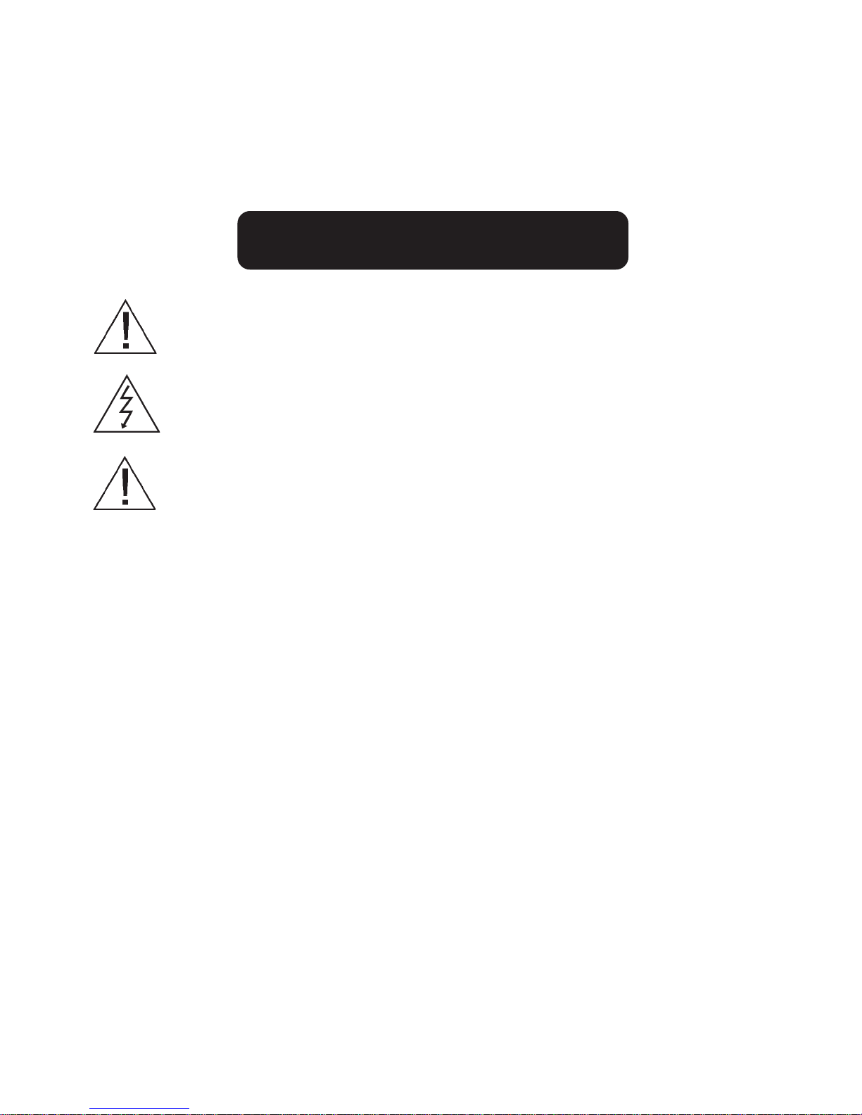
1.1 EXPLANA TION OF SYMBOLS
Some or all of the following symbols may be used in this manual or may appear on your unit. Please take a moment to
familiarize yourself with these symbols and their associated meanings.
1.2 SYSTEM DESCRIPTION
The MCP SERIES UPS is an advanced True On-Line sinewave Uninterruptible Power Supply (UPS) with automatic bypass. It
provides reliable, regulated, transient-free AC power to your sensitive equipment, ranging from computers and telecommunication systems to computerized instruments. Because the UPS is in the on-line topology type of design, conditioned power is
provided continuously to its connected devices. Unlike standby UPS’s, its on-line structure always regulates and filters output
power when commercial power is present. During line power failure, the unit employs its internal maintenance-free battery to
supply back-up power without any transfer time. In the event of an overload or inverter failure, the UPS will transfer to bypass
mode as an alternate source. The UPS can transfer back to the inverter mode automatically after the overload condition has
been cleared. All transfers noted above occur with zero transfer time that can ensure your equipment’s continuous operation.
Page 1

1.3 PRODUCT SPECIFICA TIONS
ELECTRICAL SPECIFICATIONS
Voltage
170-276
VAC
170-276
VAC
Input
Current
33A
56A
Output
Voltage
120, 120/120, 208,
120/208, 240, 120/240V
120, 120/120, 208,
120/208, 240, 120/240V
Current
50, 25/25, 28.8,
25/28.8, 25, 25/25A
83.3, 41.7/41.7, 48.1,
41.7/48.1, 41.7, 41.7/41.7A
Model
No.
MCP 6001
MCP10001
Power
Rating
6KVA
4.2KW
10KVA
7KW
Freq.
(Hz)
50/60
50/60
INPUT
Voltage: As listed
Phase: single phase with ground
Frequency: 50/60Hz +/- 5%, auto selection
Power factor: >/= 0.97
OUTPUT
Output voltage regulation: +/-3%
Power factor: 0.7 lag to unity
Frequency regulation: +/-5%, phase lock to input under normal conditions, +/-0.5% of nominal frequency,
under normal operation or battery mode.
Distortion: +/-3.0% THD at full linear load, +/-7% THD at full non-linear load
Overload Capacity: >130% +/-10% for 200 ms, 105% for 10 second
Load Crest Ratio 3:1 maximum
OPERA TING ENVIRONMENT
Ambient temperature: 10 to 40 degrees Centigrade
Operation humidity: 20% to 90%, non-condensing
Altitude: less than 1500M above sea level
Storage temperature: -15 to 40º C
MECHANICAL SPECIFICA TIONS
Model Number Dimensions
H x W x D
MCP 6001
MCP10001
31.5 x 10.25 x 23.25 in.
80 x 26 x 59 cm
38 x 13.5 x 26.5 in.
96.5 x 34.3 x 67.3 cm
Weight
Net (Shipping)
296(311.6)lb.
134.3(141.3)Kg
519.6(552.2)lb.
235.7(250.5)Kg
Page 2
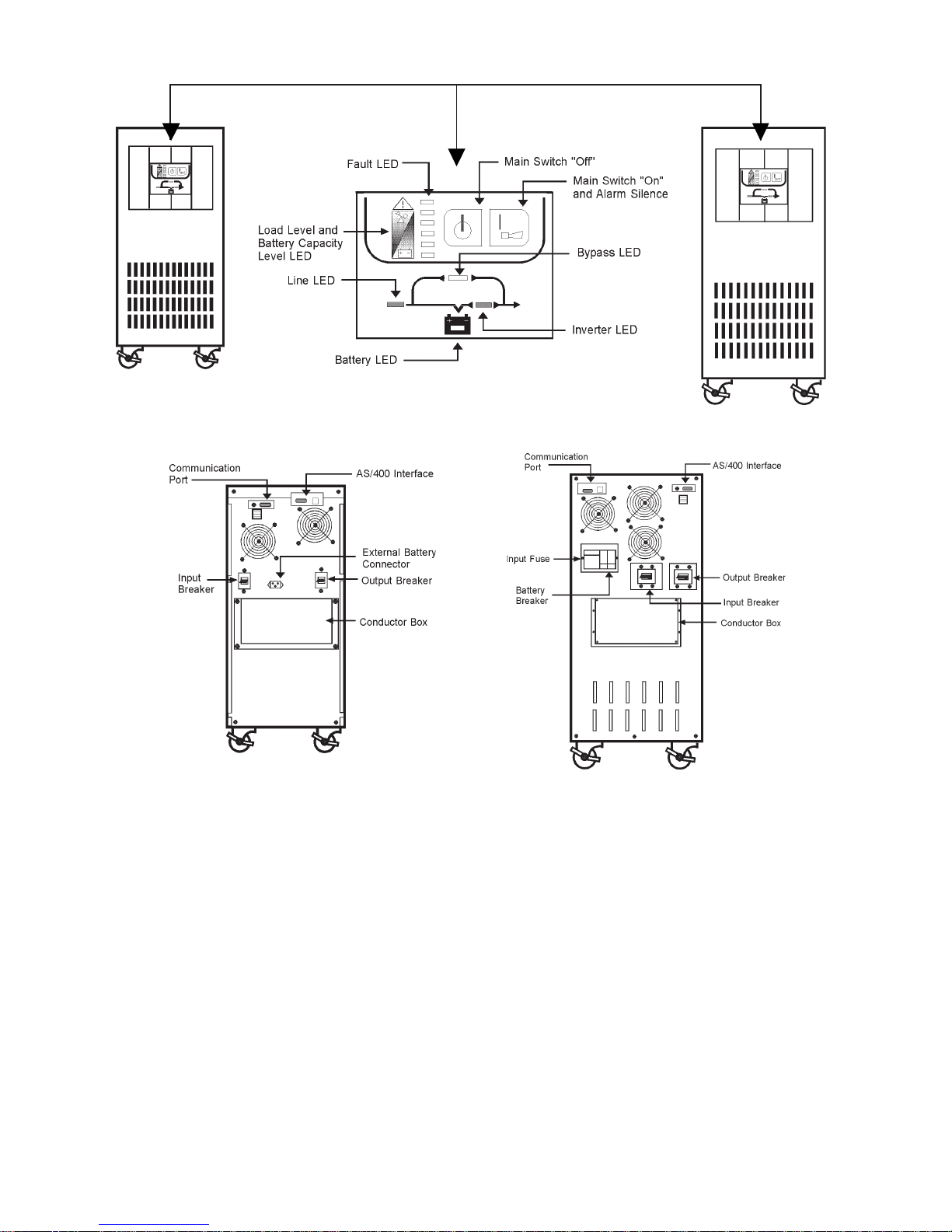
MCP 6001
Front View
MCP 6001
Rear View
MCP Control Panel
MCP 10001
Front View
MCP 10001
Rear View
1.4 SWITCHES AND DISPLA YS
◆ ON/OFF switches: Push the “ ON “ button until the alarm sounds to turn on UPS. Push “ OFF “ button until the alarm sounds
to turn off UPS.
◆ LINE LED: This light is on when the incoming AC line is normal.
◆ BYPASS LED: T his light is on when the UPS is providing power directly from the incoming AC line through the bypass route.
◆ INVERTER LED: The light is on when the UPS is operating in “ INVERTER MODE “
◆ FAULT LED: The light is on when the UPS is in fault condition and the alarm will sound continuously.
◆ LOAD LEVEL & BA TTERY CAPACITY LEVEL: The lights form the bar graph indicate how much load or battery capacity
is present in the UPS. Each LED represents a different level:
first LED 0-35%
second LED 35-55%
third LED 55-75%
fourth LED 75-95%
fifth LED 95-110%
The bar graph shows load level during line mode. The number of “ ON “ LEDs increases upwards as the load increases. The
UPS will go to battery mode when AC line power fails and the bar graph displays remaining battery capacity. The number of
“ON” LEDs decreases upwards with the decreasing of battery capacity.
Page 3
1.5 Safety
IMPORT ANT SAFETY INSTRUCTIONS
This manual contains important instructions for MCP SERIES series that SHOULD BE FOLLOWED DURING INSTALLATION
AND MAINTENANCE of the UPS and the batteries. The sound pressure level at the operator’s position is equal to or less than
60dB(A).
IMPORTANT SAFETY INSTRUCTIONS
SA VE THESE INSTRUCTIONS!
WARNING: CHANGES OR MODIFICATIONS TO THIS UNIT NOT EXPRESSL Y APPROVED BY THE
PAR TY RESPONSIBLE FOR COMPLIANCE COULD VOID THE USER’S AUTHORITY TO OPERA TE THE
EQUIPMENT.
CAUTION: TO REDUCE THE RISK OF ELECTRICAL SHOCK IN CONDITIONS WHERE LOAD EQUIP-
MENT GROUNDING CANNOT BE VERIFIED, DISCONNECT THE UPS FROM THE AC POWER OUTLET
BEFORE INST ALLING A COMPUTER INTERFACE CABLE. RECONNECT THE POWER CORD ONLY
AFTER ALL SIGNALING CONNECTIONS ARE MADE.
NOTICE: This equipment has been tested and found to comply with the limits for a Class A diigital
device, persuant to part 15 of the FCC rules. These limits are designed to provide reasonable protection
against harmful interference when the equipment is operated in a commercial environment. This equipment generates, uses and can radiate radio frequency energy and, if not installed and used in accordance with the instruction manual, may cause interference to radio communications. Operation of this
equipment in a residential area is likely to cause harmful interference, in which case the user will be
required to correct the interference at his own expense.
This digital apparatus does not exceed the Class A limits for radio noise emissions from digital apparatus set out in the Radio
interference regulations of the Canadian Department of Communications.
Le présent appeil numérique n’emit pas de bruits radioélectroniques dépassant les limites applicables aus appareils
numérique de las Class A prescrites dans le Rélement sur le brouillage radioélectronique édicte par le ministerédés Communications du Canada.
PARA SYSTEMS LIFE SUPPORT POLICY
As a general policy, Para Systems Inc. (Para Systems) does not recommend the use of any of its products in life support
applications where failure or malfunction of the Para Systems product can be reasonably expected to cause failure of the life
support device or to significantly affect its safety or effectiveness. Para Systems does not recommend the use of any of its
products in direct patient care. Para Systems will not knowingly sell its products for use in such applications unless it receives
in writing assurances satisfactory to Para Systems that (a) the risks of injury or damage have been minimized, (b) the customer
assumes all such risks, and (c) the liability of Para Systems Inc. is adequately protected under the circumstances.
Examples of devices considered to be life support devices are neonatal oxygen analyzers, nerve stimulators (whether used for
anesthesia, pain relief, or other purposes), autotransfusion devices, blood pumps, defibrillators, arrhythmia detectors and
alarms, pacemakers, hemodialysis systems, peritoneal dialysis systems, neonatal ventilator incubators, ventilators for both
adults and infants, anesthesia ventilators, and infusion pumps as well as any other devices designated as “critical” by the
United States FDA.
Hospital grade wiring devices and leakage current may be ordered as options on many PARA SYSTEMS UPS systems. PARA
SYSTEMS does not claim that units with this modification are certified or listed as Hospital Grade by PARA SYSTEMS or any
other organization. Therefore, these units do not meet the requirements for use in direct patient care.
Page 4
 Loading...