

Minuteman MC380001, MC380003, MC380000QP, MC380002QP, MC380003QP Operation Service Parts Care
...
3800
MC380000 MC380000QP
MC380001 MC380001QP
MC380002 MC380002QP
Rider Scrubber
OPERATION
SERVICE PARTS
MC380003 MC380003QP
CARE
Revised 7/02
PB # 987613
Operation, Maintenance & Troubleshooting
DUMP HOSE:
Under the recovery tank on the left side is the dump hose. This is used for dumping of the
recovery tank. To dump the recovery tank extend the hose from the machine and open the dump
valve. The dump valve is opened by flipping up the tab that is on the end of the valve. The hose
might need to be squeezed in the middle to allow the waste water to flow.
When the recovery tank is empty it is important to replace the valve on the end of the hose.
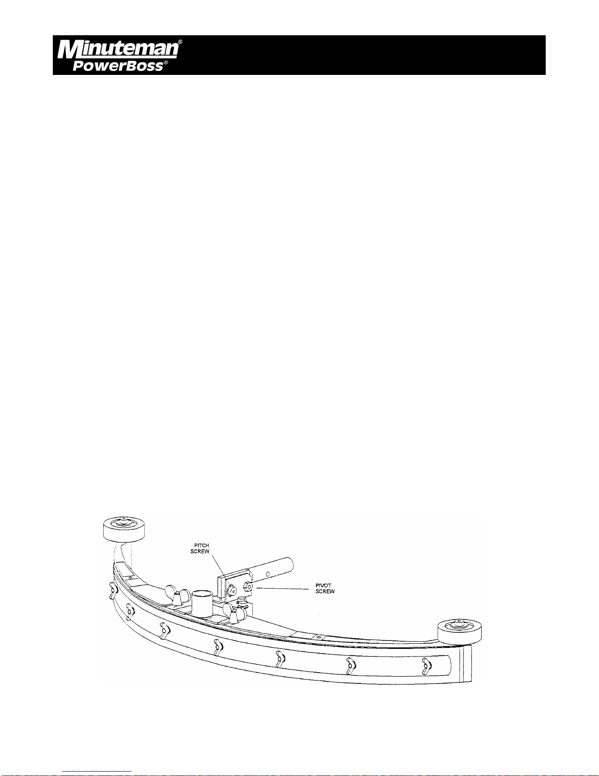
SQUEEGEE ADJUSTMENT:
The squeegee set-up is pre-adjusted at the factory. Adjustments may be required to get optimum
performance for different floors and conditions.
Pitch Control Adjustment:
Ensure that the scrubber is on a relatively flat surface. Turn on the main power switch and select
“Vacuum Only” mode.
Move the scrubber forward slowly while someone behind the machine checks the squeegee
blade for uniform deflection.
If uneven deflection or lay is evident, minor adjustments may be necessary to avoid streaking
and uneven wear on the blade.
To correct this, pitch adjustment is necessary. Loosen the pivot screw and the pitch screw. Move
the machine forward and allow the squeegee to level itself or adjust the angular position accordingly
to achieve a uniform blade deflection. Re-tighten the screws.
In certain applications where a different blade setup is required, the reinforcement blade may be
turned upside-down. The notch, which is normally on the bottom, will now be located on the top.
This adjustment allows the rear squeegee blade a larger deflection than normal.
Minuteman PowerBoss Inc. Copyright 2000
9
3800 Rider Scrubber (7/02)

Operation, Maintenance & Troubleshooting
CONTROL SETTINGS ADJUSTMENT AND MAINTENANCE MODE:
The machine settings are easily adjusted with any Windows computer equipped with Hyperterminal.
(Hyperterminal is Windows 95/98 Accessory). The program can be accessed through the “Start”
bar, scroll to “Programs” then scroll to “Accessories”. It is possible that it might be under
“Communication” under “Accessories”. Depending on the specific configuration of the computer,
the “hyperterm” icon might then need to be clicked to run the program.
Once the program is running the “New connection” menu will be open. Type in “3800 Rider” at
the connection name, then hit OK. The “Connect To” menu will then be open. The “Connect
Using” line must be changed to either “Direct to com1”, “Direct to com2”, “Direct to com3” or
“Direct to com4”. Be sure to choose the same com port that your serial input card is plugged into.
Then open the “Configure” menu (It might also be called “Properties” depending on which version
is running). The following are the correct settings.
Bits per second 4800
Data Bits 8
Parity None
Stop Bits 1
Flow Control None
Adjust all of the above to match, then hit “OK”. If the “Configure” window closes it can be opened
by clicking “Properties” under the “File” pull down window. Next, press the “Settings” tab. Under
the “Emulation” line, change it to “VT100”. Then click “OK”. The windows computer is now
configured correctly.
To connect to the 3800 rider, remove the front cover of the computer. This is located on the
steering column. Insert the communication cable (Minuteman P/N 742764) into the 3800 rider’s
computer port that is labeled “laptop”. Insert the other end of the cable into the computer interface
box (Minuteman P/N 742737). Finally, insert the computer interface box into the serial port that
the computer was configured for under “Connect to” above.
In order for the computer to communicate, the 3800 rider must be turned on. Once the machine
is turned on, the setting screen shown should appear on the computer. It is possible that “ControlL” might need to be pressed to reset the screen.
Minuteman PowerBoss Inc. Copyright 2000
10
3800 Rider Scrubber (7/02)

Operation, Maintenance & Troubleshooting
The first screen of the programming menu looks like this:
A BRUSH UP SPEED 40 40
B BRUSH DOWN SPEED 40 40
C BRUSH HYSTERESIS 8 8
D PARTIAL RAISE TIME 5 5
E PUMP START UP TIME 3 3
F (NOT USED)
G SCRUB TO RAISE BRUSH TIME 35 35
H RAISE TO BRUSH OFF TIME 5 5
I VAC TO RAISE SQUEEGEE TIME 70 70
J RAISE TO VAC OFF TIME 120 120
K (NOT USED)
L CLEAN TO FAST TRAVEL TIME 70 70
M CALIB VALUE 30 30
N MEDIUM ADDER 12 12
O HIGH ADDER 25 25
^L REDRAW SCREEN, TAB MORE PARAMS, ^P MAINTENCE
These parameters can be adjusted by pressing the letter next to the parameter that is to adjusted.
The number that is in the left column is the current setting, the number in the right column is the
“factory” setting.
The following is an explanation of the above parameters.
A. Brush up speed An indication of how fast the brush deck will be raised when it
is being adjusted for proper brush pressure. The higher the number the faster the brush deck will
go up, the lower the number, the slower the deck will go up.
B. Brush down speed An indication of how fast the brush deck will be lowered when
it is being adjusted for proper brush pressure. The higher the number, the faster the brush deck
will go down, the lower the number, the slower the deck will go down.
C. Brush hysteresis An indication of how sensitive the controller will be to changing
floor conditions. The higher the number the more sensitive, the lower the number the less sensitive. If the controller is too sensitive, it will constantly be changing the position of the scrub deck
every time that a high or low spot is encountered on the floor.
D. Partial raise time While operating in the full function or double scrub modes, the
brush deck is raised slightly after the machine is no longer moving. The amount of time that the
brush deck is raised is called the partial raise time. The larger the number the higher the scrub
deck will be raised, the lower the number the less it will be raised.
Minuteman PowerBoss Inc. Copyright 2000
11
3800 Rider Scrubber (7/02)

Operation, Maintenance & Troubleshooting
E. Pump start up time Whenever any of the pumps are turned on to any speed from
being completely off, they are first run at full speed. The length of time that the pumps are run at
full speed is called the pump start up time. The larger the number the longer the pumps will be
run at full speed, the shorter the number the shorter they will be run.
F. Not used
G. Scrub to raise brush time While operating in the full function or double scrub modes the
brush deck is raised slightly after the machine is no longer moving. The amount of time delay
between no longer moving and the brush deck raising is called the scrub to raise brush time. The
larger the number the longer the time delay will be, the smaller the number the shorter the
number will be.
H. Raise to brush off time After the brush deck has been raised there is a delay in turning
off the brushes. This is called the raise to brush off time. The larger the number the longer the
brush motors will stay on after they are raised.
I. Vac to raise squeegee time While operating in the full function or vacuum only modes, the
squeegee is raised after the machine is no longer moving. The amount of time delay between no
longer moving and the squeegee raising is called the vac to raise squeegee time. The larger the
number, the longer the delay will be, the smaller the number, the shorter the delay will be.
J. Raise to vac off time After the squeegee is raised there is a time delay before the
vacuum motors turn off. This amount of time is called the raise to vac off time. The larger the
number the longer the delay will be, the shorter the number, the shorter the delay will be.
K. Not used
L. Clean to fast travel time When going from full function, double scrub, or vacuum only
to transport mode, there is a time delay before the machine will transport at a higher speed. This
amount of time is called the clean to fast travel time. The larger the number the greater the
amount of time before the machine will go into high speed, the smaller the number, the less the
amount of time will be.
M. Calib value The value in amps that the brush motors will draw in the light
brush pressure setting is called the calib value. This value is the total amps that the motors draw.
The higher the value, the greater the scrubbing pressure will be in light brush pressure. THE
VALUE IN SETTING M PLUS SETTING N CANNOT EXCEED 55. THE VALUE IN SETTING M
PLUS THE VALUE IN SETTING O CANNOT EXCEED 55. PERMANENT MOTOR DAMAGE
WILL OCCUR!
Minuteman PowerBoss Inc. Copyright 2000
12
3800 Rider Scrubber (7/02)

Operation, Maintenance & Troubleshooting
N. Medium Adder. The additional amps that the brush motors draw in medium brush pressure is
called the medium adder. This value is added to the calib value in setting M. The higher the
value, the greater the scrubbing pressure will be in medium brush pressure. THE VALUE IN
SETTING M PLUS SETTING N CANNOT EXCEED 55. THE VALUE IN SETTING M PLUS THE
VALUE IN SETTING O CANNONT EXCEED 55. PERMANENT MOTOR DAMAGE WILL OCCUR!
O. High Adder. The additional amps that the brush motors draw in high brush pressure is
called the high adder. This value is added to the calib value in setting M. The higher the value,
the greater the scrubbing pressure will be in high brush pressure. THE VALUE IN SETTING M
PLUS SETTING N CANNOT EXCEED 55. THE VALUE IN SETTING M PLUS THE VALUE IN
SETTING O CANNONT EXCEED 55. PERMANENT MOTOR DAMAGE WILL OCCUR!
To redraw the screen press ^L.
Press TAB to get to the second programming screen. The second screen of the programming
menu looks like this:
PUMP: MIN LOW HIGH MAX
WATER(IF NORM) A 46 46 F 89 89 K 147 147 P 204 204
WATER (RECYCLE) B 33 33 G 54 54 L 83 83 Q 113 113
SOAP (IF LOW) C 13 13 H 28 28 M 46 46 R 64 64
SOAP (IF MED) D 25 25 I 59 59 N 91 91 S 120 120
SOAP (IF HIGH) E 50 50 J 114 114 O 176 176 T 255 255
^L REDRAW SCREEN, TAB MORE PARAMS, ^P MAINTENCE
These parameters can be adjusted by pressing the letter next to the parameter that is to adjusted.
The number that is in the left column is the current setting, the number in the right column is the
“factory” setting.
This table is a table of all of the water flow rates. It is not recommended that adjustments are
made since chemical metering will no longer be calibrated.
The numbers represent a speed value for the pumps: 1 is off and 255 is full speed. The first
column is the pump description, the second column is the pump speed at one light segment on
the main keyboard, the third column is the pump speed at two light segments on the main keyboard,
the fourth column is the pump speed at three light segments on the main keyboard, the fifth
column is the pump speed at four light segments on the main keyboard.
Minuteman PowerBoss Inc. Copyright 2000
13
3800 Rider Scrubber (7/02)

Operation, Maintenance & Troubleshooting
The first row is the “water (if norm)” row. This is the speed of the solution pump for the various
flow rate settings. The factory settings are .3, .7, 1.1, or 1.5 gal/min.
The second row is the “water (recycle)” row. This is the speed that the solution pump and the
recycle pump will run at if the machine is in recycle mode. The factory settings are .15, .35, .55
or .75 gal/min.
The third row is the “soap (if low)” row. This is the speed that the chemical metering pump will run
at while the machine is running in the low dilution ratio mode. This mode mixes chemical at 1oz/
gal of solution. The factory settings are .3, .7, 1.1 or 1.5 oz/gal.
The fourth row is the “soap (if med)” row. This is the speed that the chemical metering pump will
run at while the machine is running in the medium dilution ratio mode. This mode mixes chemical
at 2 oz/gal of solution. The factory settings are .6, .14, 2.2 or 3.0 oz/gal.
The fifth row is the “soap(if high)” row. This is the speed that the chemical metering pump will run
at while the machine is running in the high dilution ratio. This mode mixes chemical at 4oz/gal of
solution. The factory settings are 1.2, 2.8, 4.4 or 6.0 oz/gal.
To enter into the maintenance mode, press ^P. This mode allows maintenance personnel to
control the outputs of the controller and view the state of the inputs to the controller. The
maintenance screen looks like this:
MAINT MODE V=OVERRRIDE
a b = d e f g h i j k l m n o - - r = 0
I Chms R SolE
H Syst
G Brsh
F VacM O Recy
E Wtrs N TkFl
D Multi M OffA
L Rev
B Sq- K Fwd
A Sq+ J SysR
While in this screen, the state of the output relays are shown (a,b,d,e,f,g,h,i) and the state of the
inputs are shown (j,k,l,m,n,r). The output is “ON” if the letter is capitol and the output is “OFF” is
the letter is lower case. “ON” means that an input as +36V coming in or it means that an output
has +36V coming from it.
Minuteman PowerBoss Inc. Copyright 2000
14
3800 Rider Scrubber (7/02)

Operation, Maintenance & Troubleshooting
The description of the inputs and the outputs are as follows:
Outputs
A Squeegee raise output relay
B Squeegee lower output relay
D Multimode output relay (Connects to speed control board to engage high speed)
E Solution water solenoid output relay
F Vacuum motor output relay
G Brush motor output relay
H System start output relay
I Chemical solenoid output relay
Inputs
J System ready input
K Forward input
L Reverse input
M Off aisle cleaning input
N Recovery tank full input
O Recycle on input
R Solution empty input
The inputs/outputs are self explanatory aside from the system start and system ready. When the
operator presses “1” on the main keyboard the system start output will energize for 1 second.
This will send +36V through the recharge switch and through the keyswitch. If both of these
switches are closed then the main control relay will turn on. When the main control relay turns on
it sends +36V back to the board to the system ready input. If the board does not get +36V to the
system ready input within 1 second then the system start output will deenergize. The only reason
the system ready input would not turn on would be the recharge switch or the keyswitch being
open.
As input changes from 0V to +36V the letter on the first line will change from lower case to a
capitol letter. Conversely, as input changes from +36V to 0V the letter on the first line will change
from a capitol letter to a lower case letter.
Minuteman PowerBoss Inc. Copyright 2000
15
3800 Rider Scrubber (7/02)

Operation, Maintenance & Troubleshooting
When this screen is active the outputs cannot be changed. By pressing “V”, the controller will go
into “Override” mode. The screen will then look like this:
MAINT MODE OVERRRIDE MODE S=SQ UP/DN
a b = d e f g h i j k l m n o - - r = 0
I Chms R SolE
H Syst
G Brsh
F VacM O Recy
E Wtrs N TkFl
D Multi M OffA
L Rev
B Sq- K Fwd
A Sq+ J SysR
When this screen is active, pressing A,B,D,E,F,G,H,I will change the state of the output relays. To
raise/lower the squeegee both the A and B outputs must change. As indicated on the first line,
pressing “S” will raise/lower the squeegee (This actually is changing A and B simultaneously).
Finally, there is a number to the right of the equal sign as shown here:
a b = d e f g h i j k l m n o - - r = 0
This number is the number of amps that the brush motors are actually drawing in real time.
The line below would be 52 amps being drawn by the brush motors.
a b = d e f g h i j k l m n o - - r = 52
Minuteman PowerBoss Inc. Copyright 2000
16
3800 Rider Scrubber (7/02)

Operation, Maintenance & Troubleshooting
AFTER USE:
Turn machine off by pressing the “O” button on the control panel. Machine can be cleaned with
a mild detergent and a damp cloth. Batteries should be charged after each use or when the
battery condition meter shows a low charge. To recharge the batteries, plug the 36V charger into
the recharge port located at the left front side of the machine. The recharge port has an interlock
switch so the machine can not be turned on when the batteries are being recharged. Once the
meter on the battery charger reads 0 amps, the batteries are recharged. This should take
approximately 6-8 hours if the batteries are completely discharged.
BATTERY SERVICE AND INSTALLATION:
WARNING
Battery acid can cause burns. When working on or around batteries, wear protective clothing
and safety glasses. Remove metal jewelry. Do not lay tools or metal objects on top of batteries.
CHARGING OF BATTERIES:
Charging batteries generates explosive gasses. DO NOT CHARGE BATTERIES WHEN OPEN
FLAMES OR SPARKS ARE PRESENT. DO NOT SMOKE. Make sure the charger is turned off
before disconnecting it from the batteries. Charge the batteries in a well-ventilated area. Fluid
levels should be checked before and after charging and maintained at the proper levels. If low,
add water until the metal plates are covered. If the machine is not used for extended periods of
time, batteries should be kept fully charged with a boost charge once a week.
CARBON BRUSH REPLACEMENT:
Design life of carbon brushes is between 1800-2000 hours. Replace brushes if worn to 3/8" or
less, broken, or chipped. All carbon brushes should be replaced when motor is serviced.
Minuteman PowerBoss Inc. Copyright 2000
17
3800 Rider Scrubber (7/02)
Operation, Maintenance & Troubleshooting
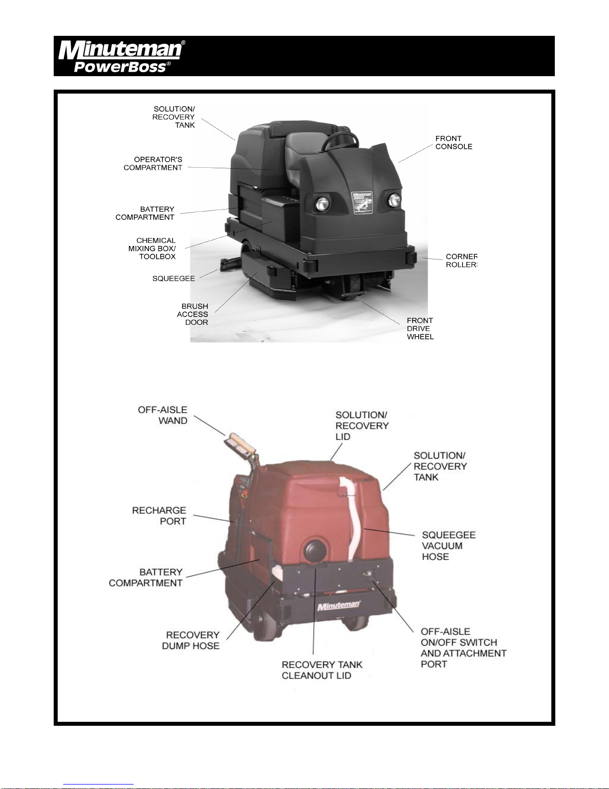
MACHINE OVERVIEW, FRONT
MACHINE OVERVIEW, REAR
Minuteman PowerBoss Inc. Copyright 2000
18
3800 Rider Scrubber (7/02)
Operation, Maintenance & Troubleshooting
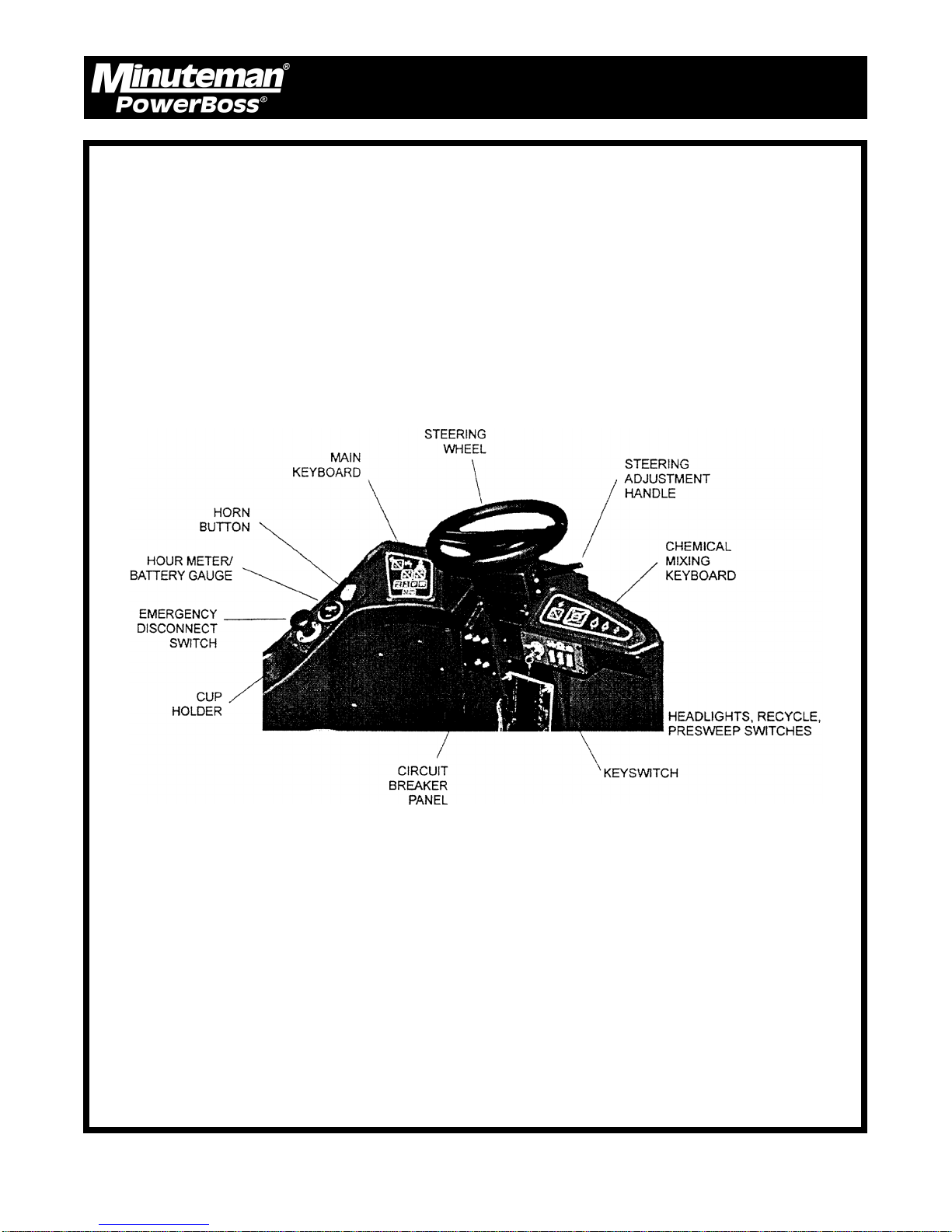
OPERATOR COMPARTMENT
Minuteman PowerBoss Inc. Copyright 2000
19
3800 Rider Scrubber (7/02)
Operation, Maintenance & Troubleshooting
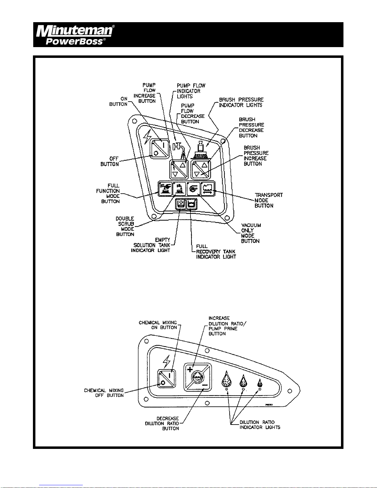
MAIN KEYBOARD
CHEMICAL MIXING KEYBOARD
Minuteman PowerBoss Inc. Copyright 2000
20
3800 Rider Scrubber (7/02)
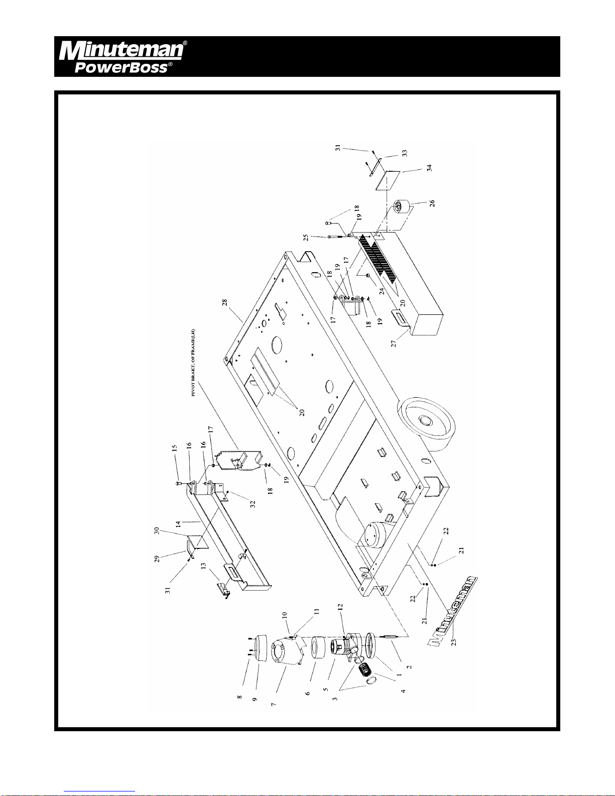
MAIN ASSEMBLY PART I
Parts
Minuteman PowerBoss Inc. Copyright 2000
24
3800 Rider Scrubber (7/02)

Parts List
ITEM PART NO. QTY. DESCRIPTION
1 290017 1 Vac Motor Gasket
2 383143 3 Vac Motor Stand-off
3 829067 2 Hose Clamps
4 383375 1 Short Vac Motor Hose
5 742772 1 Vac Motor Assy.
6 380064 1 Foam Ring
7 840012 1 Vac Motor Cover Bottom
8 711160 3 SCR-Hi/Lo #10 x 5/8
9 840011 1 Vac Motor Cover Top
10 711373 3 Nut-Nyloc 1/4-20
11 711505 3 WSR-Flat 1/4
12 832015 3 Spacer .38 x .50 x .14
13 383256 2 Latch
14 383765 1 Skirt Support Weldment LH
15 260036 4 Pin, Retainer
16 260030 4 Oilite Bushing
17 260041 4 Oilite Flange Bushing
18 711594 4 WSR-Flat .56 x .88 x .03
19 711713 4 Retaining Ring
20 383196 4 Anti-Skid Strips
21 712667 3 Nut-Hex 1/4-20 SS Nyloc
22 711504 3 WSR-Flat 1/4 SS
23 715387 1 Decal, Minuteman
24 711380 1 Nut-Hex 3/8-16 Nyloc
25 711280 1 BLT-HH 3/8-16 x 3.5
26 76-56-A 1 Roller
27 383764 1 Skirt Support Weldment RH
28 383001 1 Mainfame
29 383758 1 Skirt Retainer LH
30 383763 1 Skirt LH
31 712536 4 SCR 10-24 x .62
32 712638 4 Nut Hex 10-24 SS
33 383761 1 Skirt Retainer RH
34 383762 1 Skirt RH
Parts
Items 1-12 are optional.
Minuteman PowerBoss Inc. Copyright 2000
25
3800 Rider Scrubber (7/02)
 Loading...