

Minuteman MC380001, MC380003, MC380000QP, MC380002QP, MC380003QP Operation Service Parts Care
...Page 1
3800
MC380000 MC380000QP
MC380001 MC380001QP
MC380002 MC380002QP
Rider Scrubber
OPERATION
SERVICE PARTS
MC380003 MC380003QP
CARE
Revised 7/02
PB # 987613
Page 2
Operation, Maintenance & Troubleshooting
DUMP HOSE:
Under the recovery tank on the left side is the dump hose. This is used for dumping of the
recovery tank. To dump the recovery tank extend the hose from the machine and open the dump
valve. The dump valve is opened by flipping up the tab that is on the end of the valve. The hose
might need to be squeezed in the middle to allow the waste water to flow.
When the recovery tank is empty it is important to replace the valve on the end of the hose.
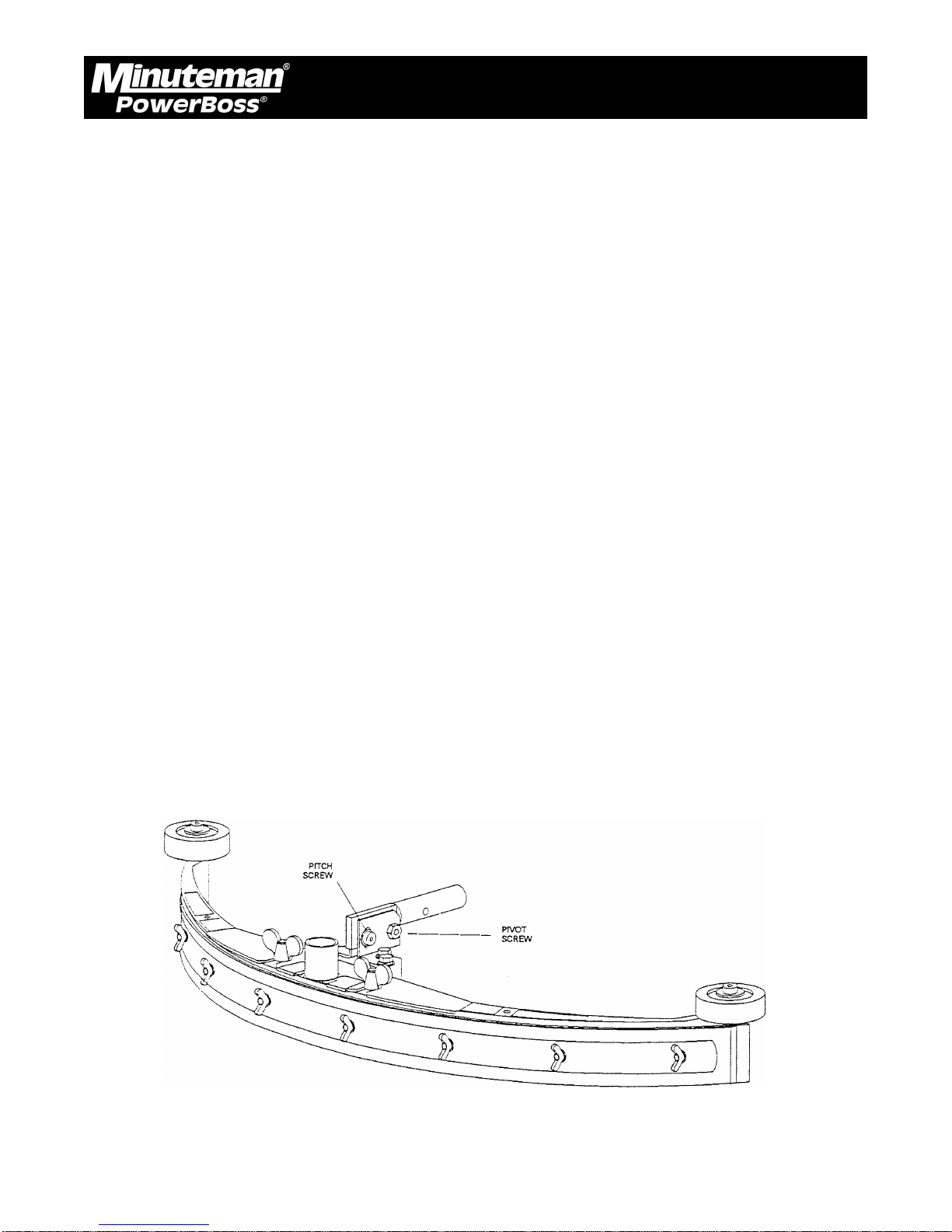
SQUEEGEE ADJUSTMENT:
The squeegee set-up is pre-adjusted at the factory. Adjustments may be required to get optimum
performance for different floors and conditions.
Pitch Control Adjustment:
Ensure that the scrubber is on a relatively flat surface. Turn on the main power switch and select
“Vacuum Only” mode.
Move the scrubber forward slowly while someone behind the machine checks the squeegee
blade for uniform deflection.
If uneven deflection or lay is evident, minor adjustments may be necessary to avoid streaking
and uneven wear on the blade.
To correct this, pitch adjustment is necessary. Loosen the pivot screw and the pitch screw. Move
the machine forward and allow the squeegee to level itself or adjust the angular position accordingly
to achieve a uniform blade deflection. Re-tighten the screws.
In certain applications where a different blade setup is required, the reinforcement blade may be
turned upside-down. The notch, which is normally on the bottom, will now be located on the top.
This adjustment allows the rear squeegee blade a larger deflection than normal.
Minuteman PowerBoss Inc. Copyright 2000
9
3800 Rider Scrubber (7/02)
Page 3

Operation, Maintenance & Troubleshooting
CONTROL SETTINGS ADJUSTMENT AND MAINTENANCE MODE:
The machine settings are easily adjusted with any Windows computer equipped with Hyperterminal.
(Hyperterminal is Windows 95/98 Accessory). The program can be accessed through the “Start”
bar, scroll to “Programs” then scroll to “Accessories”. It is possible that it might be under
“Communication” under “Accessories”. Depending on the specific configuration of the computer,
the “hyperterm” icon might then need to be clicked to run the program.
Once the program is running the “New connection” menu will be open. Type in “3800 Rider” at
the connection name, then hit OK. The “Connect To” menu will then be open. The “Connect
Using” line must be changed to either “Direct to com1”, “Direct to com2”, “Direct to com3” or
“Direct to com4”. Be sure to choose the same com port that your serial input card is plugged into.
Then open the “Configure” menu (It might also be called “Properties” depending on which version
is running). The following are the correct settings.
Bits per second 4800
Data Bits 8
Parity None
Stop Bits 1
Flow Control None
Adjust all of the above to match, then hit “OK”. If the “Configure” window closes it can be opened
by clicking “Properties” under the “File” pull down window. Next, press the “Settings” tab. Under
the “Emulation” line, change it to “VT100”. Then click “OK”. The windows computer is now
configured correctly.
To connect to the 3800 rider, remove the front cover of the computer. This is located on the
steering column. Insert the communication cable (Minuteman P/N 742764) into the 3800 rider’s
computer port that is labeled “laptop”. Insert the other end of the cable into the computer interface
box (Minuteman P/N 742737). Finally, insert the computer interface box into the serial port that
the computer was configured for under “Connect to” above.
In order for the computer to communicate, the 3800 rider must be turned on. Once the machine
is turned on, the setting screen shown should appear on the computer. It is possible that “ControlL” might need to be pressed to reset the screen.
Minuteman PowerBoss Inc. Copyright 2000
10
3800 Rider Scrubber (7/02)
Page 4

Operation, Maintenance & Troubleshooting
The first screen of the programming menu looks like this:
A BRUSH UP SPEED 40 40
B BRUSH DOWN SPEED 40 40
C BRUSH HYSTERESIS 8 8
D PARTIAL RAISE TIME 5 5
E PUMP START UP TIME 3 3
F (NOT USED)
G SCRUB TO RAISE BRUSH TIME 35 35
H RAISE TO BRUSH OFF TIME 5 5
I VAC TO RAISE SQUEEGEE TIME 70 70
J RAISE TO VAC OFF TIME 120 120
K (NOT USED)
L CLEAN TO FAST TRAVEL TIME 70 70
M CALIB VALUE 30 30
N MEDIUM ADDER 12 12
O HIGH ADDER 25 25
^L REDRAW SCREEN, TAB MORE PARAMS, ^P MAINTENCE
These parameters can be adjusted by pressing the letter next to the parameter that is to adjusted.
The number that is in the left column is the current setting, the number in the right column is the
“factory” setting.
The following is an explanation of the above parameters.
A. Brush up speed An indication of how fast the brush deck will be raised when it
is being adjusted for proper brush pressure. The higher the number the faster the brush deck will
go up, the lower the number, the slower the deck will go up.
B. Brush down speed An indication of how fast the brush deck will be lowered when
it is being adjusted for proper brush pressure. The higher the number, the faster the brush deck
will go down, the lower the number, the slower the deck will go down.
C. Brush hysteresis An indication of how sensitive the controller will be to changing
floor conditions. The higher the number the more sensitive, the lower the number the less sensitive. If the controller is too sensitive, it will constantly be changing the position of the scrub deck
every time that a high or low spot is encountered on the floor.
D. Partial raise time While operating in the full function or double scrub modes, the
brush deck is raised slightly after the machine is no longer moving. The amount of time that the
brush deck is raised is called the partial raise time. The larger the number the higher the scrub
deck will be raised, the lower the number the less it will be raised.
Minuteman PowerBoss Inc. Copyright 2000
11
3800 Rider Scrubber (7/02)
Page 5

Operation, Maintenance & Troubleshooting
E. Pump start up time Whenever any of the pumps are turned on to any speed from
being completely off, they are first run at full speed. The length of time that the pumps are run at
full speed is called the pump start up time. The larger the number the longer the pumps will be
run at full speed, the shorter the number the shorter they will be run.
F. Not used
G. Scrub to raise brush time While operating in the full function or double scrub modes the
brush deck is raised slightly after the machine is no longer moving. The amount of time delay
between no longer moving and the brush deck raising is called the scrub to raise brush time. The
larger the number the longer the time delay will be, the smaller the number the shorter the
number will be.
H. Raise to brush off time After the brush deck has been raised there is a delay in turning
off the brushes. This is called the raise to brush off time. The larger the number the longer the
brush motors will stay on after they are raised.
I. Vac to raise squeegee time While operating in the full function or vacuum only modes, the
squeegee is raised after the machine is no longer moving. The amount of time delay between no
longer moving and the squeegee raising is called the vac to raise squeegee time. The larger the
number, the longer the delay will be, the smaller the number, the shorter the delay will be.
J. Raise to vac off time After the squeegee is raised there is a time delay before the
vacuum motors turn off. This amount of time is called the raise to vac off time. The larger the
number the longer the delay will be, the shorter the number, the shorter the delay will be.
K. Not used
L. Clean to fast travel time When going from full function, double scrub, or vacuum only
to transport mode, there is a time delay before the machine will transport at a higher speed. This
amount of time is called the clean to fast travel time. The larger the number the greater the
amount of time before the machine will go into high speed, the smaller the number, the less the
amount of time will be.
M. Calib value The value in amps that the brush motors will draw in the light
brush pressure setting is called the calib value. This value is the total amps that the motors draw.
The higher the value, the greater the scrubbing pressure will be in light brush pressure. THE
VALUE IN SETTING M PLUS SETTING N CANNOT EXCEED 55. THE VALUE IN SETTING M
PLUS THE VALUE IN SETTING O CANNOT EXCEED 55. PERMANENT MOTOR DAMAGE
WILL OCCUR!
Minuteman PowerBoss Inc. Copyright 2000
12
3800 Rider Scrubber (7/02)
Page 6

Operation, Maintenance & Troubleshooting
N. Medium Adder. The additional amps that the brush motors draw in medium brush pressure is
called the medium adder. This value is added to the calib value in setting M. The higher the
value, the greater the scrubbing pressure will be in medium brush pressure. THE VALUE IN
SETTING M PLUS SETTING N CANNOT EXCEED 55. THE VALUE IN SETTING M PLUS THE
VALUE IN SETTING O CANNONT EXCEED 55. PERMANENT MOTOR DAMAGE WILL OCCUR!
O. High Adder. The additional amps that the brush motors draw in high brush pressure is
called the high adder. This value is added to the calib value in setting M. The higher the value,
the greater the scrubbing pressure will be in high brush pressure. THE VALUE IN SETTING M
PLUS SETTING N CANNOT EXCEED 55. THE VALUE IN SETTING M PLUS THE VALUE IN
SETTING O CANNONT EXCEED 55. PERMANENT MOTOR DAMAGE WILL OCCUR!
To redraw the screen press ^L.
Press TAB to get to the second programming screen. The second screen of the programming
menu looks like this:
PUMP: MIN LOW HIGH MAX
WATER(IF NORM) A 46 46 F 89 89 K 147 147 P 204 204
WATER (RECYCLE) B 33 33 G 54 54 L 83 83 Q 113 113
SOAP (IF LOW) C 13 13 H 28 28 M 46 46 R 64 64
SOAP (IF MED) D 25 25 I 59 59 N 91 91 S 120 120
SOAP (IF HIGH) E 50 50 J 114 114 O 176 176 T 255 255
^L REDRAW SCREEN, TAB MORE PARAMS, ^P MAINTENCE
These parameters can be adjusted by pressing the letter next to the parameter that is to adjusted.
The number that is in the left column is the current setting, the number in the right column is the
“factory” setting.
This table is a table of all of the water flow rates. It is not recommended that adjustments are
made since chemical metering will no longer be calibrated.
The numbers represent a speed value for the pumps: 1 is off and 255 is full speed. The first
column is the pump description, the second column is the pump speed at one light segment on
the main keyboard, the third column is the pump speed at two light segments on the main keyboard,
the fourth column is the pump speed at three light segments on the main keyboard, the fifth
column is the pump speed at four light segments on the main keyboard.
Minuteman PowerBoss Inc. Copyright 2000
13
3800 Rider Scrubber (7/02)
Page 7

Operation, Maintenance & Troubleshooting
The first row is the “water (if norm)” row. This is the speed of the solution pump for the various
flow rate settings. The factory settings are .3, .7, 1.1, or 1.5 gal/min.
The second row is the “water (recycle)” row. This is the speed that the solution pump and the
recycle pump will run at if the machine is in recycle mode. The factory settings are .15, .35, .55
or .75 gal/min.
The third row is the “soap (if low)” row. This is the speed that the chemical metering pump will run
at while the machine is running in the low dilution ratio mode. This mode mixes chemical at 1oz/
gal of solution. The factory settings are .3, .7, 1.1 or 1.5 oz/gal.
The fourth row is the “soap (if med)” row. This is the speed that the chemical metering pump will
run at while the machine is running in the medium dilution ratio mode. This mode mixes chemical
at 2 oz/gal of solution. The factory settings are .6, .14, 2.2 or 3.0 oz/gal.
The fifth row is the “soap(if high)” row. This is the speed that the chemical metering pump will run
at while the machine is running in the high dilution ratio. This mode mixes chemical at 4oz/gal of
solution. The factory settings are 1.2, 2.8, 4.4 or 6.0 oz/gal.
To enter into the maintenance mode, press ^P. This mode allows maintenance personnel to
control the outputs of the controller and view the state of the inputs to the controller. The
maintenance screen looks like this:
MAINT MODE V=OVERRRIDE
a b = d e f g h i j k l m n o - - r = 0
I Chms R SolE
H Syst
G Brsh
F VacM O Recy
E Wtrs N TkFl
D Multi M OffA
L Rev
B Sq- K Fwd
A Sq+ J SysR
While in this screen, the state of the output relays are shown (a,b,d,e,f,g,h,i) and the state of the
inputs are shown (j,k,l,m,n,r). The output is “ON” if the letter is capitol and the output is “OFF” is
the letter is lower case. “ON” means that an input as +36V coming in or it means that an output
has +36V coming from it.
Minuteman PowerBoss Inc. Copyright 2000
14
3800 Rider Scrubber (7/02)
Page 8

Operation, Maintenance & Troubleshooting
The description of the inputs and the outputs are as follows:
Outputs
A Squeegee raise output relay
B Squeegee lower output relay
D Multimode output relay (Connects to speed control board to engage high speed)
E Solution water solenoid output relay
F Vacuum motor output relay
G Brush motor output relay
H System start output relay
I Chemical solenoid output relay
Inputs
J System ready input
K Forward input
L Reverse input
M Off aisle cleaning input
N Recovery tank full input
O Recycle on input
R Solution empty input
The inputs/outputs are self explanatory aside from the system start and system ready. When the
operator presses “1” on the main keyboard the system start output will energize for 1 second.
This will send +36V through the recharge switch and through the keyswitch. If both of these
switches are closed then the main control relay will turn on. When the main control relay turns on
it sends +36V back to the board to the system ready input. If the board does not get +36V to the
system ready input within 1 second then the system start output will deenergize. The only reason
the system ready input would not turn on would be the recharge switch or the keyswitch being
open.
As input changes from 0V to +36V the letter on the first line will change from lower case to a
capitol letter. Conversely, as input changes from +36V to 0V the letter on the first line will change
from a capitol letter to a lower case letter.
Minuteman PowerBoss Inc. Copyright 2000
15
3800 Rider Scrubber (7/02)
Page 9

Operation, Maintenance & Troubleshooting
When this screen is active the outputs cannot be changed. By pressing “V”, the controller will go
into “Override” mode. The screen will then look like this:
MAINT MODE OVERRRIDE MODE S=SQ UP/DN
a b = d e f g h i j k l m n o - - r = 0
I Chms R SolE
H Syst
G Brsh
F VacM O Recy
E Wtrs N TkFl
D Multi M OffA
L Rev
B Sq- K Fwd
A Sq+ J SysR
When this screen is active, pressing A,B,D,E,F,G,H,I will change the state of the output relays. To
raise/lower the squeegee both the A and B outputs must change. As indicated on the first line,
pressing “S” will raise/lower the squeegee (This actually is changing A and B simultaneously).
Finally, there is a number to the right of the equal sign as shown here:
a b = d e f g h i j k l m n o - - r = 0
This number is the number of amps that the brush motors are actually drawing in real time.
The line below would be 52 amps being drawn by the brush motors.
a b = d e f g h i j k l m n o - - r = 52
Minuteman PowerBoss Inc. Copyright 2000
16
3800 Rider Scrubber (7/02)
Page 10

Operation, Maintenance & Troubleshooting
AFTER USE:
Turn machine off by pressing the “O” button on the control panel. Machine can be cleaned with
a mild detergent and a damp cloth. Batteries should be charged after each use or when the
battery condition meter shows a low charge. To recharge the batteries, plug the 36V charger into
the recharge port located at the left front side of the machine. The recharge port has an interlock
switch so the machine can not be turned on when the batteries are being recharged. Once the
meter on the battery charger reads 0 amps, the batteries are recharged. This should take
approximately 6-8 hours if the batteries are completely discharged.
BATTERY SERVICE AND INSTALLATION:
WARNING
Battery acid can cause burns. When working on or around batteries, wear protective clothing
and safety glasses. Remove metal jewelry. Do not lay tools or metal objects on top of batteries.
CHARGING OF BATTERIES:
Charging batteries generates explosive gasses. DO NOT CHARGE BATTERIES WHEN OPEN
FLAMES OR SPARKS ARE PRESENT. DO NOT SMOKE. Make sure the charger is turned off
before disconnecting it from the batteries. Charge the batteries in a well-ventilated area. Fluid
levels should be checked before and after charging and maintained at the proper levels. If low,
add water until the metal plates are covered. If the machine is not used for extended periods of
time, batteries should be kept fully charged with a boost charge once a week.
CARBON BRUSH REPLACEMENT:
Design life of carbon brushes is between 1800-2000 hours. Replace brushes if worn to 3/8" or
less, broken, or chipped. All carbon brushes should be replaced when motor is serviced.
Minuteman PowerBoss Inc. Copyright 2000
17
3800 Rider Scrubber (7/02)
Page 11
Operation, Maintenance & Troubleshooting
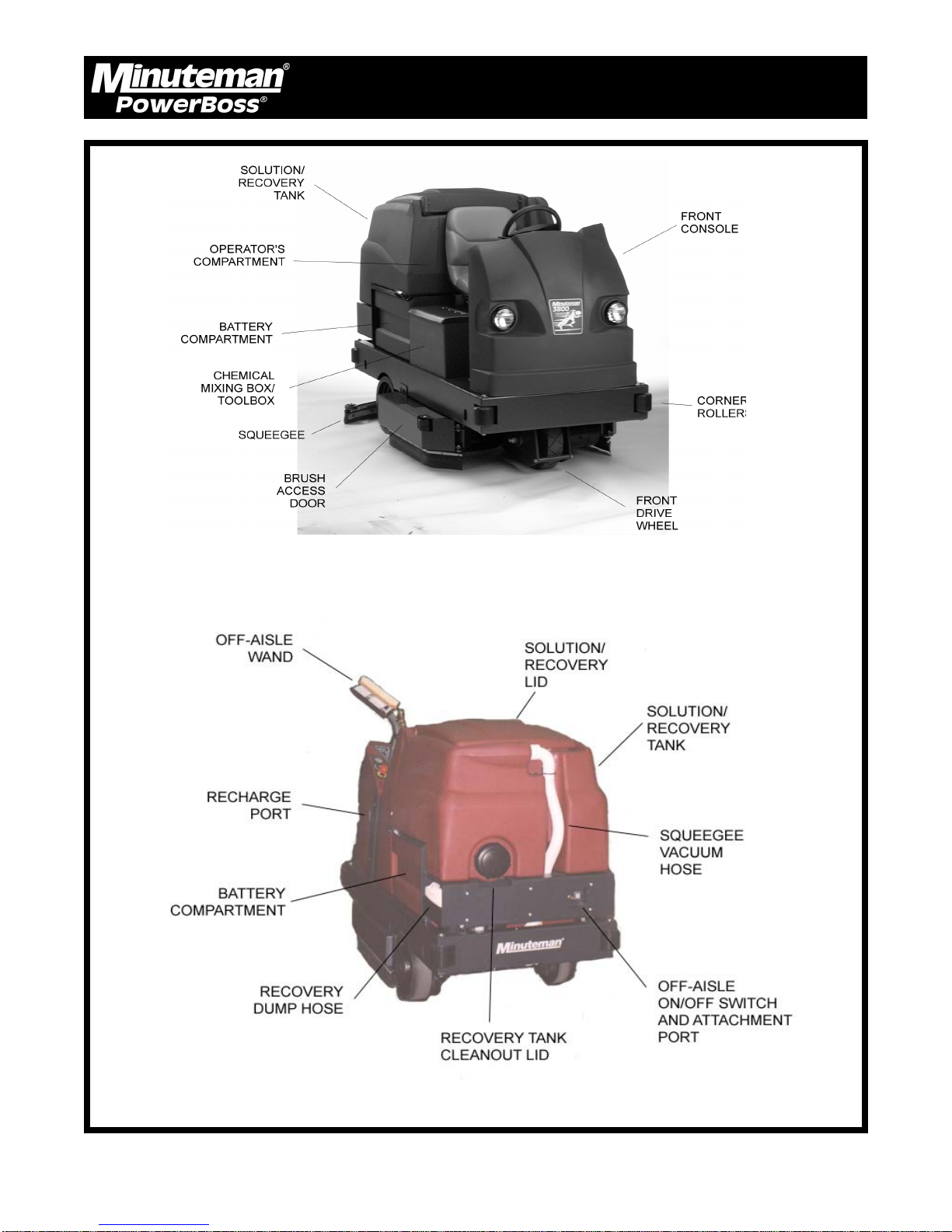
MACHINE OVERVIEW, FRONT
MACHINE OVERVIEW, REAR
Minuteman PowerBoss Inc. Copyright 2000
18
3800 Rider Scrubber (7/02)
Page 12
Operation, Maintenance & Troubleshooting
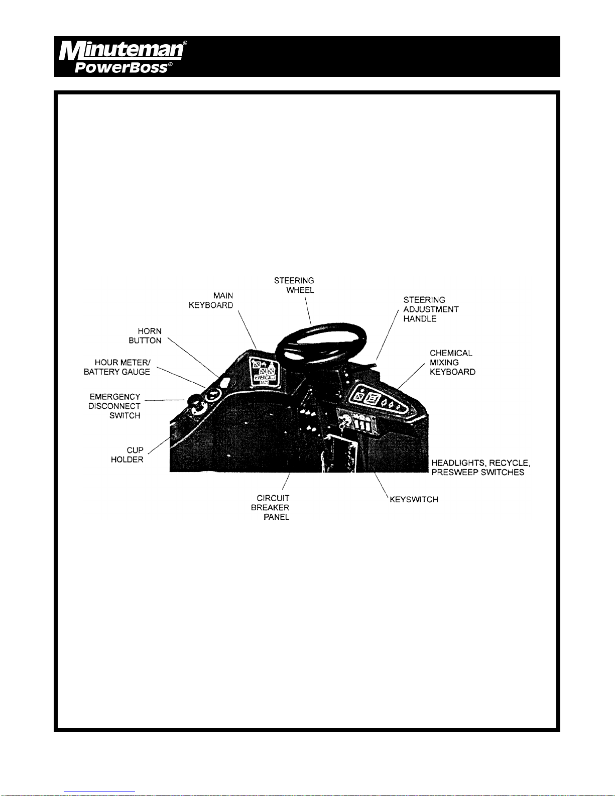
OPERATOR COMPARTMENT
Minuteman PowerBoss Inc. Copyright 2000
19
3800 Rider Scrubber (7/02)
Page 13
Operation, Maintenance & Troubleshooting
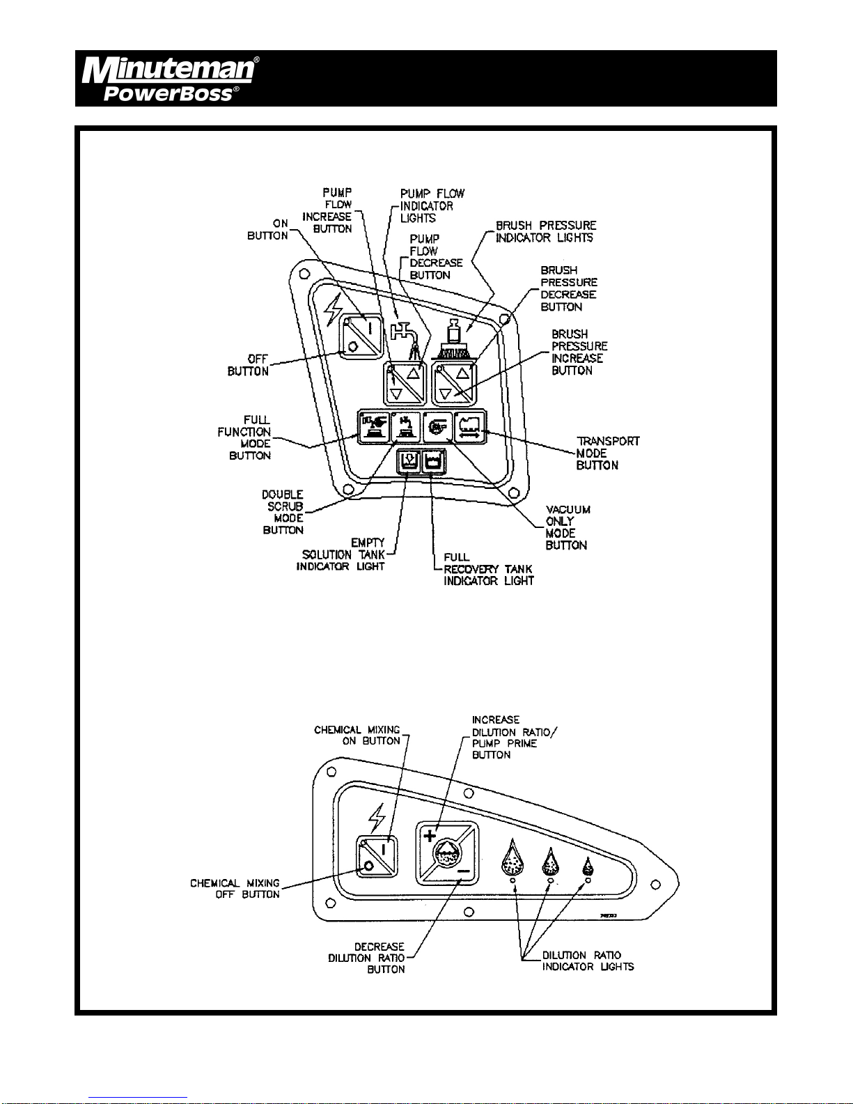
MAIN KEYBOARD
CHEMICAL MIXING KEYBOARD
Minuteman PowerBoss Inc. Copyright 2000
20
3800 Rider Scrubber (7/02)
Page 14
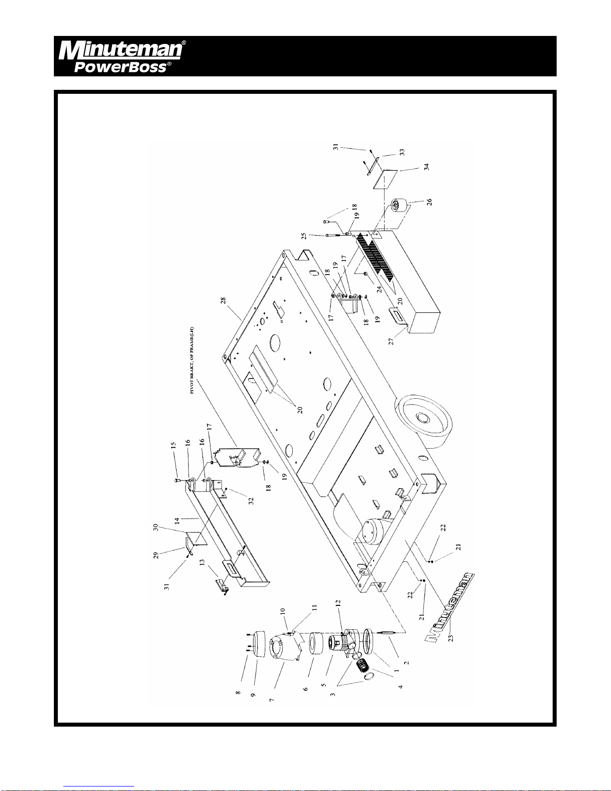
MAIN ASSEMBLY PART I
Parts
Minuteman PowerBoss Inc. Copyright 2000
24
3800 Rider Scrubber (7/02)
Page 15

Parts List
ITEM PART NO. QTY. DESCRIPTION
1 290017 1 Vac Motor Gasket
2 383143 3 Vac Motor Stand-off
3 829067 2 Hose Clamps
4 383375 1 Short Vac Motor Hose
5 742772 1 Vac Motor Assy.
6 380064 1 Foam Ring
7 840012 1 Vac Motor Cover Bottom
8 711160 3 SCR-Hi/Lo #10 x 5/8
9 840011 1 Vac Motor Cover Top
10 711373 3 Nut-Nyloc 1/4-20
11 711505 3 WSR-Flat 1/4
12 832015 3 Spacer .38 x .50 x .14
13 383256 2 Latch
14 383765 1 Skirt Support Weldment LH
15 260036 4 Pin, Retainer
16 260030 4 Oilite Bushing
17 260041 4 Oilite Flange Bushing
18 711594 4 WSR-Flat .56 x .88 x .03
19 711713 4 Retaining Ring
20 383196 4 Anti-Skid Strips
21 712667 3 Nut-Hex 1/4-20 SS Nyloc
22 711504 3 WSR-Flat 1/4 SS
23 715387 1 Decal, Minuteman
24 711380 1 Nut-Hex 3/8-16 Nyloc
25 711280 1 BLT-HH 3/8-16 x 3.5
26 76-56-A 1 Roller
27 383764 1 Skirt Support Weldment RH
28 383001 1 Mainfame
29 383758 1 Skirt Retainer LH
30 383763 1 Skirt LH
31 712536 4 SCR 10-24 x .62
32 712638 4 Nut Hex 10-24 SS
33 383761 1 Skirt Retainer RH
34 383762 1 Skirt RH
Parts
Items 1-12 are optional.
Minuteman PowerBoss Inc. Copyright 2000
25
3800 Rider Scrubber (7/02)
Page 16

MAIN ASSEMBLY PART II
Parts
Minuteman PowerBoss Inc. Copyright 2000
26
3800 Rider Scrubber (7/02)
Page 17

Parts List
ITEM PART NO. QTY. DESCRIPTION
1 383363 1 Aux. Tank Assy.
2 710329 10 SCR-MC 8-32 x .5
3 383296 1 Steering Cover
4 383250 1 Grease Cap
5 712113 1 Slotted Nut
6 383364 1 Spacer, Front Drive
7 383077 1 Roller Bearing
8 713043 4 BLT-HH 3/8-16 x 1.25
9 383200 1 Steering Assy.
10 762294MCH 1 Brake Pad
11 383064 1 Brake Pad
12 711544 4 WSR-Helical ¼
13 711202 4 BLT-HH ¼-20 x .5
14 711376 1 Nut-Nyloc ½-13
15 711524 5 WSR-Wave .52 x .87 x .01
16 809311 1 Cotter Pin 7/64
17 383230 1 Brake Pedal Cable
18 711668 1 Clevis Pin
19 711510 2 WSR-Flat .50 x 1.37 x .10
20 713042 14 BLT-HH 3/8-16 x 1 #5
21 383197 1 Accelerator Assy.
22 383225 1 Steering Mount Assy.
23 711514 1 WSR-Flat 1.06 x 2 x .15
24 807885 1 Spacer .5 x .75 x .602
25 712074 1 BLT-HH ½-13 x 2.00
26 76-58-A 1 Front Drive Assy.
27 712301 4 WSR-Flat .37 x .87 x .06
28 711546 4 WSR-Helical 3/8
29 760592 1 Oval Tapered Knob
30 383067 1 Emergency Brake Weldment
31 740132 2 Glastic Insulator
32 833638 2 Brass Stud
33 711368 2 Nut-Wing ¼-20
34 711504 7 WSR-Flat ¼ SS
35 712101 4 SCR-Hwsr. 10-24 x .50
36 383794 1 Squeegee Assy.
37 383128 1 Squeegee Actuator Assy.
38 712667 3 Nut-Nyloc 1/4-20 SS
39 712683 3 Nut-Nyloc 5/16-18 SS
40 383143 3 Vac Motor Mount
41 383153 1 Muffler, Motor
42 383374 1 Exhaust Sound Dampener
43 829067 3 Hose Clamp
44 383375 1 Short Vac Motor Hose
45 383392 1 Cap Plug
46 290017 1 Vac Motor Gasket
47 742772 1 Vac Motor Assy.
48 380064 1 Foam Ring
49 840012 1 Vac Motor Cover Bottom
50 840011 1 Vac Motor Cover Top
51 711160 3 SCR-Hi/Lo #10 x 5/8
52 711373 3 Nut-Nyloc ¼-20
53 711505 3 WSR-Flat ¼
54 832015 3 Spacer, .38 x .50 x .14
55 66-436-A 4 Corner Roller
56 809148 8 E-Ring .75
57 711517 8 WSR-Flat .77 x 1.37 x .03
58 712575 3 BLT-HH 5/16-18 x .75 SS
59 383142 1 Vac Cover Plate
60 383068 1 Gasket, Air Manifold
61 383145 4 Roller Pin
62 210033 1 Oilite Thrust Washer
63 712099PLT 1 Shoulder-Bolt 3/8 x ½
64 383469MCH 1 3/8 Compression Fitting
65 383473 1 Tubing, Copper
Parts
Minuteman PowerBoss Inc. Copyright 2000
27
3800 Rider Scrubber (7/02)
Page 18

MAIN ASSEMBLY PART III
Parts
BASIC PLUMBING, FOR MORE DETAIL SEE PG. 52
Minuteman PowerBoss Inc. Copyright 2000
28
3800 Rider Scrubber (7/02)
Page 19

Parts List
ITEM PART NO. QTY. DESCRIPTION
1 383127 1 Lever Arm Weldment
2 383467 2 Fitting Brass 1/2 x 1/2
3 383325 1 Fitting Brass Tee 1/2 FPT
4 383465 2 Fitting Brass Nipple 1/2 MPT
5 742718 1 Water Solenoid 36V
6 383457 1 Hydraulic Manifold, Upper
7 383480 1 Fitting Brass 1/8 MPT Plug
8 3400261 2 Fitting Brass 1/4 MPT x 3/8 Barb
9 383479 1 Fitting Brass 3/8 MPT Plug
10 711668 1 Clevis Pin
11 383229 1 Brake Cable (from 3838350)
12 81-44-A 1 Nylon Pulley
13 711808 1 Spring Cup
14 383461 1 1” Ball Valve
15 383471 2 Fitting Brass 1” MPT x 1”
16 710230 4 SCR 8-32 x .62
17 711426 4 8-32 Wizz Nut
18 383474 2 Clip, 1” Hose
19 712680 4 Nut Hex 5/16-18 Ss
20 711545 4 WSR Helical 5/16
21 383226 1 Squeegee mechanism
22 260064 1 Flanged Tube
23 383068 1 Gasket, Air Manifold
24 383238 1 Air Manifold, Bottom
25 383237 1 Air Manifold, Top
26 712767 6 WSR-Flat .406 x .75
27 712683 6 Nut-Hex 5/16-18
28 712547 6 SCR 10-24 x 2.5” SS
29 383458 1 Hydraulic Manifold, Lower
30 383468 2 Fitting Brass 3/4 x 3/4
31 809236 2 Oilite Flanged Bushing
32 711526 4 WSR-Wave 1.01 x 1.20 x .01
33 809237 2 Retaining Ring
34 260066 2 Oilite Flange Bushing
35 260041 2 Oilite Flange Bushing
36 383368 2 Spacer .384 x .500 x .437
37 383369 2 Spacer .384 x .500 x .219
38 712100 1 Shld-Blt 3/8 x 2.25
39 712119 1 Shld-Blt 3/8 x 3
40 711374 2 Nut-Nyloc 5/16-18
42 742712-1 1 Actuator 36V
43 742711 1 Horn
44 710180 1 SCR 1/4-20 x .75
45 711505 1 WSR-Flat 1/4
46 711373 1 Nut-Nyloc 1/4-20
47 383414 1 Cover, Electrical Cable
Parts
Minuteman PowerBoss Inc. Copyright 2000
29
3800 Rider Scrubber (7/02)
Page 20

MAIN ASSEMBLY PART V
Parts
Minuteman PowerBoss Inc. Copyright 2000
30
3800 Rider Scrubber (7/02)
Page 21

Parts List
ITEM PART NO. QTY. DESCRIPTION
1 383425 1 Filter Bracket, Lower
2 383446 2 Gasket, 1.125 x 2.75 x .125
3 383447 2 Spacer, 1.125 x 1.625 x .125
4 711922 2 Rivet Tube, .19 x .28
5 712764 2 WSR-SS #10
6 383448 1 Anchor Coupling
7 807901 1 Bolt SP, Machined
8 383246 1 Filter Bracket, Upper
9 712680 1 Nut-Hex 5/16-18 SS
10 340071 1 Recycle Filter 340
11 340067 1 Gasket, Recycle Filter
12 340069 1 Cover Recycle Filter
13 711369 1 Nut, Wing 5/16-18 Nylon
14 383303 1 Lid
15 712120 2 Shoulder Bolt, 1/2 x 2 PLT
16 383397 1 Gasket, Solution
17 383297 1 U Channel
18 383264 1 Roll Pin .125 x 1.00
19 711161 3 SCR-Hi/Lo #10 x 3/4
20 383263 1 Prop Rod
21 760263 1 Double Sided Tape
22 383026 1 Gasket Recovery
23 383030 1 Gasket Solution
24 840059 1 Cap, Thread Cover
25 383231 1 Clip, Screw Down
26 383135 1 Solution/Recovery Tank (w/o Recovery)
27 742708-2 1 Float w/Male Term.
28 383454 1 Vacuum Equalizing Tube 9.41 ft.
29 712540 10 SCR-MC 10-24
30 383184 1 Tank Bottom Cover
31 260203 1 Hose Clamp, 102120
32 383273 1 1.5” Vac Hose x 52”
33 383449 1 Fitting Brass 90 ° 1/2 x 1/2
34 740132 2 Glastic Insulator
35 383270 2 Tool Clip
36 710230 4 SCR-MC 8-32 x .62
37 711372 4 Nut-Nyloc 8-32
38 711502 4 WSR-Flat #8
39 130040PTD 2 Handle
40 711505 4 WSR-Flat 1/4
41 711544 4 WSR-Helical 1/4
42 713002 4 BLT-HH 1/4-20 x 3/4
43 712083 6 BLT-Flange Wizz Loc 3/8-16
44 383165 1 Tank Frame Weldment
45 383291 2 Hinge
46
47 383272 1 2” Wireloc Hose
48 809311 2 Cotter Pin 7/64 x 1
49 712301 2 WSR-Flat .37 x .87 x .06
50 711523 2 WSR-Wave .37 x .68 x .08
51 260066 2 Oilite Flanged Bushing
52 711592 2 WSR-Nylon .5 x 1.06 x .06
53 710197 4 SCR-MC 5/16-18 x 3/4
54 383235 1 Back Door Weldment
55 711579 1 WSR-Flat .56 x 1.00
56 3400261 1 Fitting Brass 1/4 MPT x 3/8 Barb
57 740811 1 Dreefs Switch Boot
58 740800CE 1 Momentary Dreefs Switch
59 828368 1 BH2-61 Male Coupler
60 742833 1 Cable Assy.
61 383186 1 Hose Hook
62 712534 4 SCR-MC 10-24 x .5
63 380032 1 Strain Relief
64 712812 2 SCR 10-24 x .62 PHL
65 711543 2 WSR-Helical #10
66 711599 2 WSR-Flat .187 x 1.00 x .06
67 742710-1 1 Backup Alarm
68 383185 1 Switch Cover Rear
69 711368 2 Nut-Wing 1/4-20
70 833638 2 Brass Stud
71 220174 1 Fitting Brass 90° 1/4 MPT x 3/8 Barb
Items 1 thru 13 and 27 are included with Model #MC380001 & MC380003.
Items 64 thru 67 are optional.
Parts
Minuteman PowerBoss Inc. Copyright 2000
31
3800 Rider Scrubber (7/02)
Page 22

MAIN ASSEMBLY PART IV
Parts
ITEM PART NO. QTY. DESCRIPTION
1 383225 1 Steering Mount Assy.
2 260030 1 Oilite Bushing
3 383076 1 Race (large)
4 383075 1 Roller Bearing
5 383074 1 Lip Seal
6 832554 3 Flange Bushing
7 711713 1 Retaining Ring
8 711578 2 WSR-Flat 1/2
9 760601 2 Sprocket
10 807071 1 Spacer, 3/4
11 430149 1 Bushing .531 x 1 x .25 SS
12 711524 1 WSR-Wave, .52 x .87 x .01
13 711380 2 Nut-Nyloc 3/8-16
Minuteman PowerBoss Inc. Copyright 2000
Parts List
ITEM PART NO. QTY. DESCRIPTION
14 712301 2 WSR-Flat .37 x .87 x .06
15 383405 1 Idler Arm Weldment
16 383078 1 Race, Small
17 383050 1 Rear Axle Weldment
18 711171 4 BLT-HH 7/8-9 x 4.5”LG
19 383090 4 Snubbing Washers
20 742709-1 1 Water Pump, 36V
21 710363 4 SCR 10-32 x 1.5
22 711426 4 Nut-Hex 10-32
23 3330913 1 Key 1/4 x 1/4 x .75
24 3400930 1 SCR 5/16-18 x .75
25 3400233 1 WSR-Fender 5/16
Optional 2nd Pump w/Recycling Package
32
3800 Rider Scrubber (7/02)
Page 23

MAIN ASSEMBLY PART VI
Parts
ITEM PART NO. QTY. DESCRIPTION
1 383073 2 Battery Liner Spacers
2 383095 1 Battery Cover
3 383096 1 Battery Liner
4 383042 2 Battery Straps
5 383227 1 Scrubhead Assy.
6 956715 6 6 Volt Battery
7 383127 1 Lever Weldment
8 260066 2 Oilite Flange Bushing
9 711523 2 WSR-Wave .37 x .68 x .08
10 712301 2 WSR-Flat .37 x .87 x .06
11 809311 2 Cotter Pin 7/64 Dia.
Minuteman PowerBoss Inc. Copyright 2000
Parts List
ITEM PART NO. QTY. DESCRIPTION
12 711592 2 WSR-Nylon .5 x 1.06 x .06
13 712075 2 BLT-HH ½ - 13 x 1.5
14 711502 2 WSR-Flat #8
15 807885 2 Spacer .50 x .75 x .602
16 383226 1 Squeegee Mach. Assy.
17 383794 1 Squeegee Assy.
18 383144 1 Auxiliary Out Decal
19 383259 1 Rec. Tank Drain Hose
20 383260 1 Discharge Tube
21 750402 1 Plug Assembly
22 340464 1 Clamp, Hose
33
3800 Rider Scrubber (7/02)
Page 24

CONSOLE ASSEMBLY
Parts
Minuteman PowerBoss Inc. Copyright 2000
34
3800 Rider Scrubber (7/02)
Page 25

Parts List
ITEM PART NO. QTY. DESCRIPTION
1 383290 1 Cover, Connector
2 710178 4 SCR-MC ¼-20 x .50 STPL
3 710177 2 SCR-MC ¼-20 x .37
4 383289 2 Bracket, Connector
5 712540 8 SCR-MC 10-24 x .37
6 710307 2 SCR-MC 6-32 x 1.00
7 740147 1 Grey Housing
8 711316 2 Nut-Hex ¼-20
9 383310 1 Bracket, Recharge
10 740128 1 Snap Switch
11 711430 1 Tinnerman Nut
12 711209 2 BLT-HH ¼-20 x 1.12
13 724747 1 Cover, Charge Port
14 711157 4 SCR Hi/Lo #7-19 x .50
15 715246 1 Decal, Battery 36V
16 742703 1 Emergency Disconnect
17 383151 1 Dashboard Plate
18 715402 1 Decal, Dashboard Left
19 742310 1 Hour Meter
20 712822 18 SCR-MC 10-24 x .50
21 383378 1 Bezel Dashboard
22 742736 1 Switch, Horn
23 383376 1 Bezel Keyboard
24 742701 1 Keyboard
25 715403 1 Decal, Console
26 711160 8 SCR Hi/Lo #10 x 5/8
27 383213 2 Headlight Cover
28 742733 1 MEM-Switch, Chemical Mix
29 383268 2 Console Bracket
30 710180 8 SCR-MC ¼-20 x .75
31 383394 1 Insulator
32 711550 12 WSR-Nylon .25 X .75 0D
33 712665 8 Nut-Hex ¼-20 SS
34 742700 1 Computer, 3800
35 383305 1 Computer Cover, Left
36 383304 1 Computer Cover, Middle
37 710153 6 SCR-MC 10-32 x .37
38 383306 1 Computer Cover, Right
39 711161 10 SCR Hi/Lo #10 x .75
40 210405 1 Liquid Tight Fitting
41 383393 1 Insulator
42 383377 1 Bezel, Chemical Mix
43 383149 1 Right Side Dash Plate
44 740247 1 Circuit Breaker 30A
45 740238 1 Circuit Breaker 18A
46 740249 1 Circuit Breaker 50A
47 740131 2 Circuit Breaker 70A
48 741005 1 Key Switch
49 383147 1 Key Switch Plate
50 742716 1 Switch, 1 Pole w/Splash
51 715401 1 Decal, Key Switch
52 715276 1 Circuit Breaker
53 383150 1 Circuit Breaker Plate
54 711131 2 SCR-MC Self Tap #8 x .37
55 742728 1 Terminal Block
56 742954 1 Electrical Assy. 3800
57 711544 6 WSR-Helical ¼
58 383395 1 Insulator
59 383267 1 Electrical Panel Cover
60 711162 2 SCR Hi-Lo #10 x 1.50
61 742704 2 Headlight
62 742748 5 Circuit Breaker Boot
63 383300 1 Console, 3800
64 383310 1 Recharge Bracket
Parts
Items 28 and 42 are optional with Model #MC380002 and #MC380003.
Item 50 has optional 2nd and 3rd switch.
Items 60 and 61 are optional.
Minuteman PowerBoss Inc. Copyright 2000
35
3800 Rider Scrubber (7/02)
Page 26

STEERING COLUMN ASSEMBLY
Parts
Minuteman PowerBoss Inc. Copyright 2000
36
3800 Rider Scrubber (7/02)
Page 27

Parts List
ITEM PART NO. QTY. DESCRIPTION
1 210033 2 Oilite Thrust Washer
2 260041 2 Oilite Flange Bushing
3 363-816 1 Nut-Nyloc 1/2-20
4 383098 2 Universal Joint
5 383152 1 Steering Wheel
6 383171 1 Locking Pin Shaft
7 383172 1 Locking Pin Head
8 383211 1 Housing, Compression Spring
9 383214 1 Pivot Arm
10 383215 1 Upper Bracket Weldment
11 383218 1 Steering Weldment
12 383221 1 Spring, Compression
13 383277 1 Woodruff Key, 3/16 x 3/4
14 383278 1 Shaft, Upper Steering
15 383279 1 Shaft, Middle Steering
16 383280 1 Shaft, Lower Steering
17 383284 1 Cover, Steering Top
18 383285 1 Cover, Steering Bottom
19 383296 1 Cover, Steering Weldment
20 3331835 2 SCR-MC 8-32 x .50 STPL
21 710360 2 SCR-MC 10-32 x 1.0 STPL
22 710961 1 SCR-SC 1/4-20 x .37
23 711350 2 Nut Nyloc 10-32
24 711380 2 Nut Nyloc 3/8-16
25 711803 1 Cotter Pin .06 x .75
26 712099PLT 2 BLT-Shoulder 1/2 x 1/2
27 712117 1 Clevis Pin 3/16 x 19/32
28 712310 1 WSR-Flat .52 x .87 x .06
29 712811 8 SCR-MC 10-24 x .5 STPL
30 760043 4 Key .187 Sq. x .675
31 809148 1 E-Ring .75
32 3330940 2 Bearing Flange, 3/4
33 833629 1 Master Chain Link
34 383407 4 Valcro Strips 1” Lg.
35 3400009 4 SCR-CAR 5/16-18 x 1.00
36 3400088 4 WSR-Flat 5/16
37 3400080 4 Nut-Nyloc 5/16-18
Parts
Minuteman PowerBoss Inc. Copyright 2000
37
3800 Rider Scrubber (7/02)
Page 28

SOLUTION/RECOVERY ASSEMBLY
Parts
Minuteman PowerBoss Inc. Copyright 2000
38
3800 Rider Scrubber (7/02)
Page 29

Parts List
ITEM PART NO. QTY. DESCRIPTION
1 383138 1 Bladder Frame
2 383089 1 Bladder Bag
3 383139 1 Bladder Plate
4 383101 1 Bladder Gasket
5 383141 2 Angle Bladder, Top-Bottom
6 383140 2 Angle Bladder, Side
7 130029 4 Grommet, .75 x .31 x .25
8 715206 1 Decal-Rec., Tank Cover
9 383210 1 1 1/2” Adapter, MPT
10 383379 1 Elbow 1 1/2” PVC
11 840099 1 Filter Screen
12 840102 1 Cap, Filter
13 833160 2 1.5” Pipe Coupling
14 430095 2 PVC Bushing, 1.5 x 1.25
15 383365 1 Stand Pipe, 1.5
16 383302 1 Solution/Recovery Tank
17 712683 22 Nut-Hex 5/16-18
18 712579 22 WSR-Flat .31 x 1.37 x .06
19 840059 22 Cap, Thread Cover
20 383146 1 Solution Strainer
21 383046 1 MPT Reducer, 3/4” x 1/2”
22 828970 1 WSR-Neoprene 1.87 x 2.4 x .125
23 450081 1 WSR-SS 1.908 x 2.41 x .03
24 450083 1 Insert Fit, White
25 340047 1 3/4” Barb Fitting
26 715205 1 Decal, Solution Tank Cover
27 420013 2 Tube 1/2” x 3” Lg.
28 742708-2 1 Float Switch with Male Term
29 742833 1 Cable Assy.
30 383319 1 Fitting Plug, 1/2 MPT
31 383318 1 2” MPT x 2” Barb
32 383401 1 Plate, Gasket Backing
33 383402 1 Gasket, Dump Cover
34 383437 1 Cap, Dump Cover
Parts
Minuteman PowerBoss Inc. Copyright 2000
39
3800 Rider Scrubber (7/02)
Page 30

SCRUBHEAD ASSEMBLY
Parts
Minuteman PowerBoss Inc. Copyright 2000
40
3800 Rider Scrubber (7/02)
Page 31

Parts List
ITEM PART NO. QTY. DESCRIPTION
1 383951 1 WB Motor Pan
2 210066 2 Drive Hub Retainer Belt
3 383053 2 Lift Bracket Weldment
4 383228 2 Nylon Nut 3/8 NPT
5 430163 2 Drive Hub w/Steel Insert
6 710986 8 SCR-SC 3/8-16 x 1.00
7 711546 8 WSR-Helical 3/8
8 711517 2 WSR-Flat .77 x 1.37 x .03
9 833621 2 Key 1/4 x 1/4 x 1
10 712575 6 BLT-HH 5/16-18 x .75 SS
11 711545 6 WSR-Helical 5/16
12 712680 6 Nut 5/16-18 SS
13 742714 2 36V Motor (1 hp)
14 711506 4 WSR-Flat 5/16 ST PL
15 320255 2 BRK, Spring Support
16 711671 4 Clevis Pin .31 x 2.13
17 3400755 2 Clevis Pin 1/2 x 2.25
18 260137 2 Compression Spring
19 711594 2 WSR-Flat .56 x .88 x .03
20 3400124 6 5/8 Rue Ring
21 383768 1 Bracket Side Squeegee, LH
22 383780 1 Bracket Side Squeegee, RH
23 3402010 4 SCR-Hex 3/8-16 x 1.25
24 3400336 4 WSR-3/8 Flat
25 3300339 4 Sleeve Bushing
26 711592 8 WSR .5 x 1.06 x .06
27 3400340 4 Nut-Hex 3/8-16 SS
28 3400058 13 SCR-TRS 1/4-20 x 1.00
29 383779 1 Retainer-Side Squeegee LH
30 383778 1 Strip-Backup Side Squeegee LH
31 383777 1 Squeegee, Side LH
32 383771 1 Weld-Squeegee Mnt. LH
33 3400126 4 Pin Hitch 1/2 x 1.50
34 383782 1 Weld-Squeegee Mnt. RH
35 383784 1 Squeegee Side RH
36 383785 1 Strip Backup Side Squeegee RH
37 383786 1 Retainer Side Squeegee RH
38 3400063 13 Nut Flange Lock 1/4-20
39 3400261 2 Fitting Brass 1/4 MPT x 3/8 Barb
40 3400125 4 3/8 Rue Ring
41A 381036 2 Dyna Scrub Brush
41B 381037 2 Power Scrub Brush
41C 381038 2 Pad Holder
41D 381039 2 Nylon Brush
41E 381040 2 Poly-Grit Brush
41F 381041 2 Strata-Grit Brush
Parts
Minuteman PowerBoss Inc. Copyright 2000
41
3800 Rider Scrubber (7/02)
Page 32

OFF AISLE WAND
Parts
Minuteman PowerBoss Inc. Copyright 2000
42
3800 Rider Scrubber (7/02)
Page 33

Parts List
ITEM PART NO. QTY. DESCRIPTION
1 383411 1 Wand AL, 1 1/4
2 832285 1 1 1/2 End Coupling
3 832284 1 Nut
4 100004 1 Bracket, Spray Jet
5 711903 4 Rivet, Pop .19 x .46
6 829115 1 Vee Jet, 1/4 NPT
7 711594 3 WSR-Flat .56 x .88 x .03
8 833384 1 Check Valve, 1/4
9 832884 1 Spacer
10 828953 1 Flare Connector
11 833488 1 HB Swivel Fl. 14HBLFSV-4-4
12 828490 4 Crimp Clamp
13 828488 3’ Hose
14 831327 2 1/4 MPT x 1/4 Hose Barb
15 828488 .42 Hose
16 829106 1 1/4 MPT Barb
17 390052 1 Body
18 828370 2 Coupler
19 390055 1 Cap
20 390054 1 Valve
21 390062 1 O-Ring
22 390049 1 Spring
23 712320 3 WSR #10
24 390061 1 O-Ring
25 390060 1 O-Ring
26 390063 1 Pin
27 711803 1 Cotter Pin
28 390053 1 Trigger
29 712636 1 Nut-Hex 10-32 SS
30 712545 1 SCR-MC 10-32 .87
31 390056 1 Valve Mount
32 762173 1 Tube, Shrink
33 500295 2 Rubber, Squeegee
34 500296 2 Rubber, Reinforcing
35 800615 2 Retaining Strip
36 833789 2 Bracket Mounting
37 833841 1 Brush
38 711106 14 SCR-ST-A #10 x .75
39 833789 2 Bracket Mounting
40 808648 1 Nozzle, Squeegee
41 801045 1 Hose, CP 1 1/2 x 15 ft.
42 383416 1 Cuff Enlarger, 1 1/2 Hose
43 828488 16’ Hose
44 828490 2 Crimp Clamp
45 828106 2 1/4 MPT Barb
46 828368 1 BH2-51 Male Coupler
47 828062 5 Cable Ties
48 383254 1 Hose Cuff
Parts
Minuteman PowerBoss Inc. Copyright 2000
43
3800 Rider Scrubber (7/02)
Page 34

FRONT DRIVE ASSEMBLY
Parts
ITEM PART NO. QTY. DESCRIPTION
1 383108 1 Drive Wheel
2 383112 1 Drive Wheel Hub
3 383113 1 Front Drive Motor Assy.
4 400935 6 SCR-SOC Hd. Cap 5/16-24
5 383115 1 Front Drive Wheel Weldment
6 383118 2 Spacer 1 Dia. x 6.813 Lg.
7 383119 1 Spraver 2.5 x 1 x .375
8 383286 1 Chain Disc Weldment
9 383373 1 Steering Chain
10 711164 1 Bolt 1 x 5.0 Lg.
11 711165 1 Nut-1 Nyloc
12 711166 5 Lug Nut ½-20
13 711167 3 Bolt M12-1.75 x 25 MM
Minuteman PowerBoss Inc. Copyright 2000
Parts List
44
ITEM PART NO. QTY. DESCRIPTION
14 713027 8 Bolt 5/16-18 x 1 GR5
15 713028 3 Bolt 5/16-18 x 1.25 GR5
16 713071 6 Bolt ½ -13 x 1.50 GR5
17 809247 3 Spacer .502 x .38 x .322
18 383433 1 Spacer 1.75 OD x 1.06 ID
19 383104 1 End Plate
20 383103 1 Gear Box
21 383070 1 Drive Plate
22 400926 6 SCR-SOC Hd. Cap 5/16-24
23 383069 5 Isolators
24 400041 4 BLT-Helical ¼ SS
25 712758 4 WSR-HH ¼-20 ZP
26 711504 4 WSR-Flat ¼ SS
3800 Rider Scrubber (7/02)
Page 35

AUXILIARY TANK ASSEMBLY
Parts
ITEM PART NO. QTY. DESCRIPTION
1 383154 1 Seat
2 713002 4 BLT-HH ¼-20 x ¾
3 711544 8 WSR-Helical ¼
4 711505 8 WSR-Flat ¼
5 383155 1 Seat Mount
6 383301 1 Auxiliary Tank
7 711203 4 Bolt-HH ¼-20 x .62
8 383131 1 Mount Plate
9 383144 1 Cover, Chemical Mix
10 712908 7 Nut-Flanged Wizz 10-24
11 450021 1 Hinge
12 712816 7 SCR-MC 10-24 x .37
13 383129 1 Chem Mix Enclosure
14 828893 6 Rivet Bap KTR64BX
15 711379 2 5/16-18 Wizz Nut
16 383321 1 Fitting PP, 3/4 MPT x 3/4 Barb
17 742708-1 1 Float Switch
18 383346 1 Crimp Clamp 3/4
19 383217 1 Battery Cable Cover
20 383269 1 Off-Aisle Bracket
21 383270 1 Spring Clip
* 383384 and 383390 included with Models MC380002 & MC380003.
Minuteman PowerBoss Inc. Copyright 2000
Parts List
ITEM PART NO. QTY. DESCRIPTION
22 711503 2 WSR-Flat #10
23 711915 2 Rivet Tube .19 x .28
24 711160 4 SCR-Hi/Lo #10 x 5/8
25 383132 1 Chem. Pump Bracket
26 383359 1 Hose, 1/4 x 32.5 Lg.
27 383386 1 1/4 Barb x 1/8 MPT Brass
28 383428 1 Hose 1/4 x 6.75” Lg.
29 383429 1 Hose, 1/4 x 2” Lg.
30 710153 2 SCR-MC 10-32 x .37
31 712822 2 SCR-MC 10-24 x .5
32 711503 4 WSR-Flat #10
33 711543 4 WSR-Helical #10
34 742713 1 Pump, Chemical Meter
35 742719 1 Solenoid 36V
36 828490 3 Crimp Clamp 140R
37 383472 2 Fitting Brass 90, 1/8 MPT x 1/4 Barb
38 383094MCH 1 Chemical Bottle
39 383386 1 Fitting Brass 1/4 Barb x 1/8 FPT
40 383388 1 1/4 ID x 10 1/4 PP Tube
41 3302338 1 Worm Clamp
45
3800 Rider Scrubber (7/02)
Page 36

ACCELERATOR ASSEMBLY
Parts
ITEM PART NO. QTY. DESCRIPTION
1 210033 2 Oilite Thrust Washer
2 210375 1 Swivel Pin
3 210391 2 Return Spring
4 210405 1 Liquid Tight Fitting
5 383158 1 Switch Cover
6 383188 1 Pedal Weldment
7 383189 1 Mounting Plate
8 383191 1 Throttle Bar
9 383193 1 Accelerator Bar Weldment
10 383196 1 Anti-Skid Strip
11 710252 4 SCR-MC 10-32 x .25
12 711003 1 SCR-SK 10-32 x .25
13 711231 1 BLT-HH 5/16-18 STPL
Minuteman PowerBoss Inc. Copyright 2000
Parts List
ITEM PART NO. QTY. DESCRIPTION
14 711374 1 Nut-Nyloc 5/16-18
15 711420 1 Nut-Hex Jam 5/16-18
16 711504 2 WSR-Flat ¼ ID SS
17 711506 2 WSR-Flat 5/16 STPL
18 712320 2 WSR-Nylon .22 x .45 x .04
19 712536 2 SCR-MC 10-24 x .62 SS
20 712562 1 BLT-HH ¼-20 x .75 SS
21 712758 5 WSR-Helical ¼ SS
22 742913 1 Throttle Assembly
23 75-89-A 1 Speed Nut
24 828988 1 Heycoflex Conduit
25 829052 1 Flange Bushing Nylon .312 ID
46
3800 Rider Scrubber (7/02)
Page 37

REAR AXLE ASSEMBLY
Parts
ITEM PART NO. QTY. DESCRIPTION
1 383051 1 Rear Axle Weldment
2 383177 2 Drum Brake (Knott 180x30)
3 383111 2 Rear Wheel
4 383194 4 Bearing Cone
5 383195 4 Bearing Cup
6 711169 8 ½-20 UNF FSHS
7 711450 2 1-14 UNS-2A Slotted Nut
Minuteman PowerBoss Inc. Copyright 2000
Parts List
ITEM PART NO. QTY. DESCRIPTION
8 380-632-20 2 3/16 Cotter Pin
9 711514 2 Washer
10 383241 2 Grease Cap
11 383072 4 Ring & Bushing Isolator
12 383426 2 Clevis Pin ¼ x .88 Zinc PLT
13 711808 2 Cotter Pin, Hair #13
14 383229 1 Brake Cable
47
3800 Rider Scrubber (7/02)
Page 38

ACTUATOR SUPPORT ASSEMBLY
Parts
ITEM PART NO. QTY. DESCRIPTION
1 881002 1 Clevis Pin 5/16 x .88
2 320161 1 Bracket, Squeegee Cable
3 712638 1 Nylon Nut, 10-24 SS
4 712764 1 WSR-SS, #10
5 712540 1 SCR-MC 10-24 x .37
6 742735 1 Actuator
7 833277PLT 2 Actuator Bushing
8 711720 2 Retaining Ring-E Ext. .25
9 383123 1 Actuator Support Weldment
10 833294 1 Actuator Pin
11 711133 1 Self Tapping Screw #8 x .37
Minuteman PowerBoss Inc. Copyright 2000
Parts List
48
ITEM PART NO. QTY. DESCRIPTION
12 742728 1 Terminal Block
13 383162 2 Clevis Pin 3/8 x 3 3/4
14 383476 1 Roller
15 711507 4 Flat Washer 3/8”
17 711668 1 Clevis Pin 3/8 x 1.0
18 383436 1 Actuator Cable
19 809311 4 Cotter Pin 7/64” x 1.0
20 383430 1 Actuator Cover
21 711202 2 BLT-HH 1/4-20 x .5 STPL
22 711505 2 WSR-Flat 1/4
3800 Rider Scrubber (7/02)
Page 39

SQUEEGEE MECHANISM
Parts
ITEM PART NO. QTY. DESCRIPTION
1 383311 1 Yoke Weldment
2 383224 1 Spring Housing Weldment
3 320008 1 Pivot Bracket Weldment
4 383314 1 Swivel Pin
5 260041 2 1/2 Oilite Bushing
6 383287 2 Torsion Spring SS
7 711671 1 Clevis Pin 5/16 x 2.125
8 712565 2 SCR-MC 1/4-20 x .62 SS
9 383315 2 Spacer Tube
10 710392 2 SCR-MC 1/4-20 x 4.50 SLTD
13 711715 2 3/4 Retaining Ring
14 712562 1 Bolt-HH ¼-20 x .75 SS
15 712758 1 WSR-Helical ¼ SS
16 711504 1 WSR-Flat .25 ID SS
17 711808 1 Cotter Pin
18 711505 2 WSR-Flat ¼
19 711517 2 WSR-Flat .75 x 1.375 x .09 SS
Minuteman PowerBoss Inc. Copyright 2000
Parts List
49
3800 Rider Scrubber (7/02)
Page 40

SQUEEGEE ASSEMBLY
Parts
ITEM PART NO. QTY. DESCRIPTION
Parts List
ITEM PART NO. QTY. DESCRIPTION
17 383754 1 Front Squeegee Blade
18 383789 1 Squeegee Mounting Bracket
19 711578 2 WSR-Flat ½ Brass
20 220249 2 Wing Bolt ½-13 x .75
21 383424 1 Mounting Bracket - Right
22 320154 1 Squeegee Mount Weldment
23 383425 1 Mounting Bracket - Left
24 712301 4 WSR-Flat .37 x .87 x .07
25 711379 1 Nut-Flanged Wizz 5/16-18
1 712091 2 Bolt-Shoulder 3/8 x 1.5
2 711507 2 WSR-Flat .37 x 1.12 x .06
3 711592 2 WSR-Nylon .50 x 1.06 x .06
4 808829 2 Squeegee Bumper Wheel
5 832015 2 Spacer
6 383750MCH 1 Squeegee Machined
7 383753 1 Rear Squeegee Blade
8 383755 1 Reinforcement Blade
9 383751 1 Rear Blade Strap
26 711374 1 Nut-Nyloc 5/16-18
27 712562 4 Bolt-HH ¼-20 x .75 SS
28 712578 4 WSR-Helical ¼ SS
29 712081 2 Bolt-Shoulder 3/8 x .75
30 383792 1 Gasket, Squeegee Mount Brkt.
10 711504 8 Wing Nut ¼-20 SS
12 712571 2 Bolt-SS Carr ¼-20 x 1.5
13 712573 2 Bolt-SS Carr ¼-20 x 2.5
14 712574 2 Bolt-SS Carr ¼-20 x 3.00
15 712577 2 Bolt-SS Carr ¼-20 x 3.5
16 383752 1 Front Blade Strap
Minuteman PowerBoss Inc. Copyright 2000
50
3800 Rider Scrubber (7/02)
Page 41

PLUMBING DIAGRAM
Parts
Minuteman PowerBoss Inc. Copyright 2000
51
3800 Rider Scrubber (7/02)
Page 42

3800 RIDER SCHEMATIC DIAGRAM
Parts
Minuteman PowerBoss Inc. Copyright 2000
52
3800 Rider Scrubber (7/02)
Page 43

3800 RIDER MAIN ASSEMBLY
WIRING DIAGRAM
Parts
Minuteman PowerBoss Inc. Copyright 2000
53
3800 Rider Scrubber (7/02)
Page 44

3800 RIDER UNDER FRAME
WIRING DIAGRAM
Parts
Minuteman PowerBoss Inc. Copyright 2000
54
3800 Rider Scrubber (7/02)
Page 45

3800 RIDER FRONT CONSOLE
WIRING DIAGRAM
Parts
Minuteman PowerBoss Inc. Copyright 2000
55
3800 Rider Scrubber (7/02)
Page 46

Parts
3800 RIDER
WIRE COLOR
WIRING GUIDE
Black Negative Computer Only
Black/Green Float Low Solution Black Negative 742872
Black/Orange 0-5V Accelerator Black/Green Float Low Solution 742816
Black/White Forward - Accelerator Black/White Forward - Accelerator 742895
Blue Shunt Blue Shunt
Blue/White Shunt Blue/White Shunt
Blue/Orange Brush Actuator Blue/Orange Brush Actuator 742812
Blue/Green Brush Actuator Blue/Green Brush Actuator 742811
Blue/Yellow Horn Brown Float Hi Rec 742815
Brown Float Hi Rec Grey Chemical Solenoid Valve 742802
Brown/White Drive Relay Coil Grey/Red Water Solenoid Valve 742804
Brown/Yellow Headlights Grey/Yellow Recycle Pump 742807, 742808
Grey Chemical Solenoid Valve Orange/Black Chemical Pump 742814
Grey/Red Water Solenoid Valve Orange/Red Chemical Pump 742813
Grey/Yellow Recycle Pump Red Positive 742889
Orange Pot Low Red/Violet System Ready 742917
Orange/Black Chemical Pump Red/White Multimode 742899
Orange/Red Chemical Pump Violet/Black Water Pump 742809, 742810
Red Positive White Reverse Accelerator 742896
Red/Violet System Ready White/Blue Off Aisle Switch 742819
Red/White Multimode White/Violet System Start 742882
Red/Yellow Forward Relay Coil Yellow Recycle 742894
Violet Seat Switch Yellow/Violet Vacuum Relay Coil 742866
Violet/Black Water Pump Yellow/Red Brush Relay Coil 742870
Violet/Yellow Reverse Relay Coil Yellow/Orange Squeegee Actuator 742821
White Reverse Accelerator Yellow/Blue Squeegee Actuator 742820
White/Blue Off Aisle Switch
White/Orange Presweep
White/Violet System Start
Yellow Recycle
Yellow/Violet Vacuum Relay Coil
Yellow/Red Brush Relay Coil
Yellow/Orange Squeegee Actuator
Yellow/Blue Squeegee Actuator
Orange/Violet Presweep Raise
Black/Yellow Presweep Actuator
Minuteman PowerBoss Inc. Copyright 2000
56
3800 Rider Scrubber (7/02)
Page 47

3800 RIDER COMPUTER
WIRING GUIDE
MAIN BOARD
Parts
Connector
742745
Connector
742744
Inputs
Side Closest to Input Connector
System Start White/Violet 742882
Brush On Yellow/Red 742870
Outputs
Vacuum On Yellow/Violet 742866
Water Solenoid Grey/Red 742804
Multimode Red/White 742899
Spare
Squeegee Actuator Yellow/Orange 742821
Squeegee Actuator Yellow/Blue 742820
Water Pump Violet/Black 742809
Water Pump Violet/Black 742810
Brush Actuator Blue/Orange 742812
Brush Actuator Blue/Green 742811
Side Closest to RJ11 Plug
Shunt+ Blue
Shunt- Blue/White
System Ready Red/Violet 742917
Forward Black/White 742895
Reverse White 742896
Off Aisle White/Blue 742819
Recovery Tank Full Brown 742815
Solution Tank Empty Black/Green 742835
Spare
Connector
742743
Minuteman PowerBoss Inc. Copyright 2000
OPTION BOARD
Side Closest to Main Board
Chemical Pump Orange/Red 742813
Chemical Pump Orange/Black 742814
Recycle Pump Grey/Yellow 742807
Recycle Pump Grey/Yellow 742808
Chemcial Solenoid Grey 742802
Recycle On Yellow 742894
57
3800 Rider Scrubber (7/02)
Page 48

LIMITED WARRANTY
Minuteman International, Inc. warrants to the original purchaser/user that this product is free from defects in workmanship and
materials under normal use and service for a period of three years from date of purchase. In addition, Minuteman International,
Inc. will, at its option, honor labor warranty claims for the first 12 months from date of sale, provided such claims are submitted
through and approved by factory authorized repair stations. Minuteman International, Inc. will, at its option, repair or replace
without charge, except for transportation costs, parts that fail under normal use and service when operated and maintained in
accordance with the applicable operation and instruction manuals.
This warranty does not apply to normal wear, or to items whose life is dependent on their use and care, such as belts, cords,
switches, hoses, rubber parts, electrical motor components or adjustments. Parts not manufactured by Minuteman International,
Inc. such as engines, batteries, battery chargers, hydraulic pumps, and tires are covered by and subject to the warranties and/
or guarantees of their manufacturers. Please contact Minuteman International, Inc. for procedures in warranty claims against
these manufacturers.
Special warning to purchaser — Use of replacement filters and/or prefilters not manufactured by Minuteman International, Inc.
or its designated licensees, will void all warranties expressed or implied.
A potential health hazard exists without exact original equipment replacement.
All warranteed items become the sole property of Minuteman International, Inc. or its original manufacturer, whichever the case
may be.
Minuteman International, Inc. disclaims any implied warranty, including the warranty of merchantability and the warranty of
fitness for a particular purpose. Minuteman International, Inc. assumes no responsibility for any special, incidental or consequential damages.
This limited warranty is applicable only in the U.S.A. and Canada, and is extended only to the original user/purchaser of this
product. Customers outside the U.S.A. and Canada should contact their local distributor for export warranty policies. Minuteman
International, Inc. is not responsible for costs or repairs performed by persons other than those specifically authorized by Minuteman International, Inc. This warranty does not apply to damage from transportation, alterations by unauthorized persons, misuse
or abuse of the equipment, use of non-compatible chemicals, or damage to property, or loss of income due to malfunctions of the
product.
If a difficulty develops with this machine, you should contact the dealer from whom it was purchased.
This warranty gives you specific legal rights, and you may have other rights which vary from state to state. Some states do not
allow the exclusion or limitation of special, incidental or consequential damages, or limitations on how long an implied warranty
lasts, so the above exclusions and limitations may not apply to you.
World Headquarters PowerBoss
Minuteman International, Inc. 175 Anderson Street
111 South Rohlwing Road Aberdeen, North Carolina
Addison, Illinois 60101 28315 USA
(630) 627-6900 (910) 944-2167
FAX (630) 627-1130 FAX (910) 944-3199
987613
Printed in U.S.A.
 Loading...