

Minuteman MC32036QP, MC32036CE Service Manual
320
Model: MC32036QP
Floor Scrubber
Traction Driven
OPERATION
SERVICE PARTS
MC32036CE
CARE
Revised 8/03
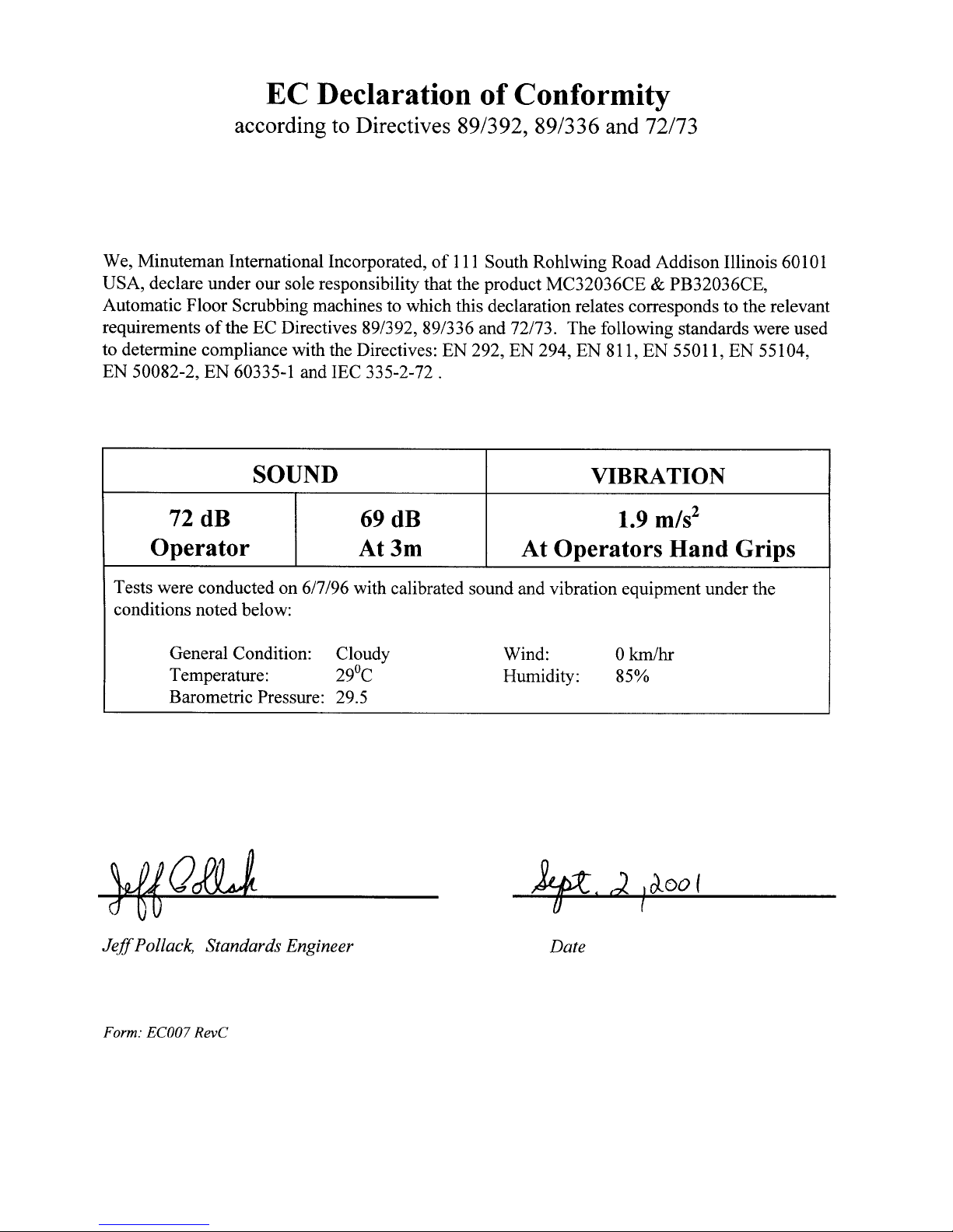

TABLE OF CONTENTS
Page
Safety Instructions 1
Electrical Requirements 2
Control Panel Identification 3
Squeegee Adjustments 4
Operating Instructions 5
Maintenance of Machine 6 & 7
Main Polyethylene Components 8 & 9
Recovery Tank 10
Solution Tank 11
Drive Assemblies 12 &13
Main Frame 14 & 15
Console Assembly 16 & 17
Scrubhead Assembly 18
Squeegee Mechanism Assembly 19
Squeegee Assembly Complete 20
Wiring Diagram Standard Model 21
Wiring Diagram CE Model 22

IMPORTANT SAFETY INSTRUCTIONS
CAUTION
Operators must read and understand this manual before operating or maintaining
this equipment.
• Keep hands and feet clear of moving parts while machine is in operation.
• All switches must be in the “OFF” position when charging batteries.
• Electrical motors and components can cause an explosion when operated near explosive materials
or vapors. Do not operate this machine near flammable materials such as solvents, thinners, fuels,
grain dusts, etc.
• Make sure all switches are turned “OFF” and battery connections are removed before performing
any maintenance procedures.
• Store or park this machine on a level surface only.
• These machines are designed for level floor operation only. DO NOT OPERATE on ramps or
inclines.
• Battery acid can cause burns. When working on or around batteries, wear protective clothing and
safety glasses. Remove metal jewelry. Do not lay tools or metal objects on top of batteries.
• This machine is not suitable for picking up hazardous dust.
• Charging batteries generates explosive gases. DO NOT CHARGE BATTERIES WHEN OPEN
FLAMES OR SPARKS ARE PRESENT. DO NOT SMOKE. Make sure the charger is turned off
before disconnecting it from the batteries. Charge the batteries in a well-ventilated area.
• Maintenance and repairs must be performed by authorized personnel.
SAVE THESE INSTRUCTIONS
1
ELECTRICAL REQUIREMENTS:
This piece of equipment operates on 36 Volt DC.
BATTERY REQUIREMENTS:
6 x 6V 220AH P/N 956720
6 x 6V 275AH P/N 956740
BATTERY SERVICE AND INSTALLATION:
* Warning: Battery acid can cause burns. When working on or around batteries, wear protective
clothing and safety glasses. Remove metal jewelry. Do not lay tools or metal objects on top of batteries.
BATTERY INSTALLATION:
1. Raise tank assembly by raising rear cover and disconnecting vacuum recovery hose, Fig. 1.
2. Tilt recovery tank.
3. Install batteries as shown in figure 2.
CHARGING OF BATTERIES:
Charging of batteries generates explosive gases. DO NOT CHARGE BATTERIES WHEN OPEN
FLAMES OR SPARKS ARE PRESENT. DO NOT SMOKE. Make sure the charger is turned off
before disconnecting it from the batteries. Charge the batteries in a well-ventilated area. Fluid levels
should be checked before and after charging and maintained at the proper levels.
2
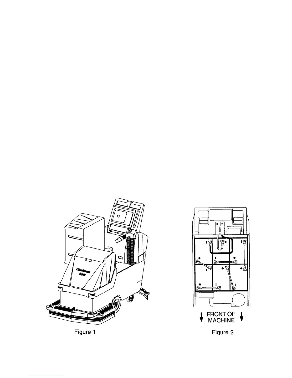
CONTROL PANEL IDENTIFICATION
AUTO SCRUBBER BRUSH DESCRIPTION
TYPE DESCRIPTION DURABILITY* COLOR COMPARISON RECOMMENDED
TO PADS USE
Bassine Natural Fiber Short DarkBrown Red Light duty
Nylon Nylon Medium Black Tan/Red General cleaning
Dyna-Scrub Nylon impregnated Long Light Red General scrubbing,
with 500 Grit Blue vinyl tile, ceramic
Silicone Carbide tile, epoxy floors,
Fine Bristle, urethane finish,
Dense Fill uneven concrete floors
Power-Scrub Nylon impregnated Long Rust Red/Blue Moderate aggressive
with 120 Grit Silicon scrubbing, tile floors
Carbide Fine Bristle, concrete floors
Dense Fill
Poly-Grit Nylon impregnated Long Green Brown/Black Aggressive stripping
with 80 Grit and scrubbing, tile
Silicon Carbide floors, unfinished
Coarse Bristle concrete floors
Strata-Grit Nylon impregnated Long Dark Black Heavy duty
with 46 Grit Blue stripping/scrubbing
Silicon Carbide unfinshed
Coarse Bristle concrete
general cleaning,
acid etching
& scrubbing vinyl
floors, ceramic tile
& concrete floors
* Durability is dependent on floor surface, chemicals used and proper care.
3
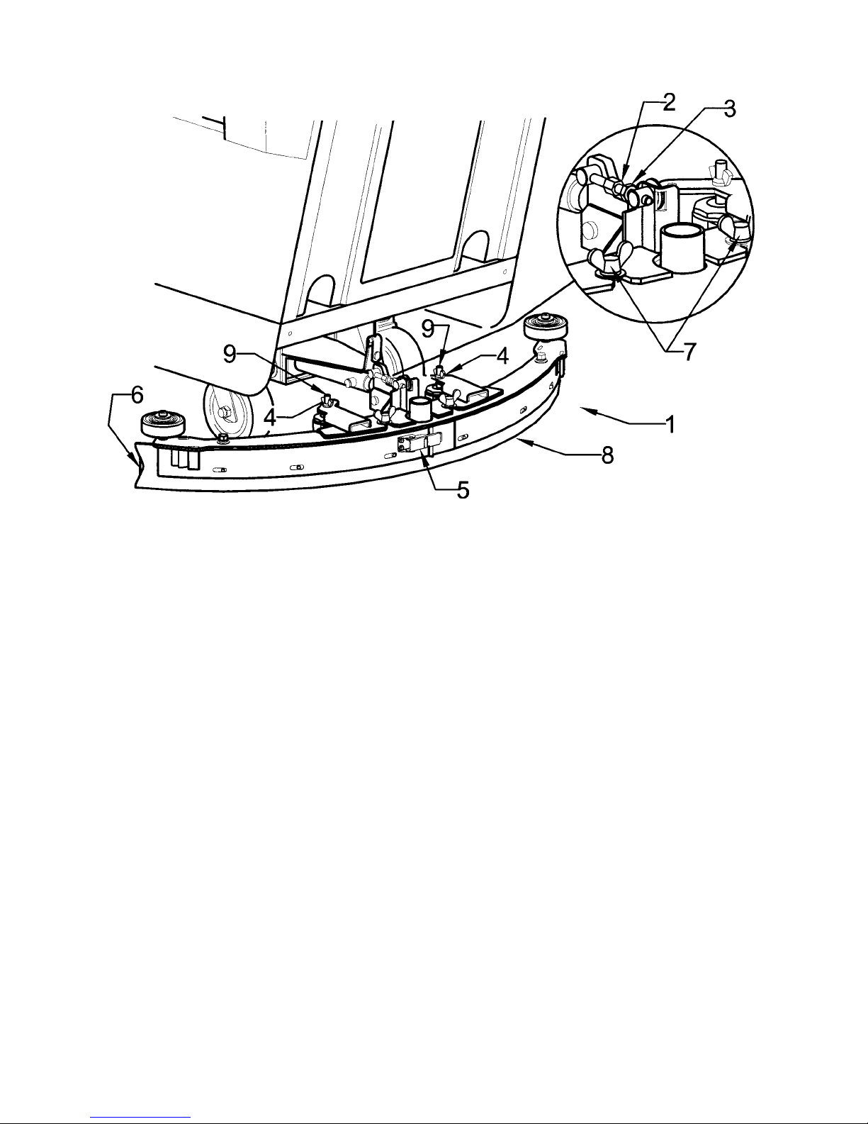
SQUEEGEE ADJUSTMENTS
The squeegee set-up is pre-adjusted at the factory. Adjustments may be required to get optimum performance for
different floors and conditions.
1. Ensure that the scrubber is on a relatively flat surface. Turn on the main power switch and raise the scrub
head assembly off the floor. Set the squeegee/ vacuum switch to the automatic mode.
2. Turn the speed control knob counter-clockwise to the low speed position. Squeeze the forward control lever to lower
the squeegee (item 1) to the floor. Move the machine one or two feet forward to check the rear squeegee blade (item
8) for uniform deflection to the floor.
3. If uneven deflection or lay is evident, minor adjustments may be necessary to avoid streaking and uneven wear on
the blade.
4. To correct this, loosen the wing jam nut (item 4) in order to adjust the caster height. If the squeegee blade is
deflecting too much, the casters need to be lowered to control the down pressure. Lower the caster by turning the
exposed threaded stem (item 9) on the caster clockwise. Make the adjustment a few turns at a time.
5. Repeat step 2.
6. In certain applications where a different blade set-up is required, the reinforcement blade (item 4) may be turned
upside down. The notch, which is normally on the bottom will now be located on the top side. This adjustment
allows the rear squeegee blade a larger deflection than normal.
7. Make sure that there is an even deflection on the entire length of the rear blade. Adjust the castors and retighten the
wing jam nuts to lockthe caster setting in place.
8. Pitch adjustment is necessary if the outer ends on the squeegee blade does not contact the floor and there is too
much deflection in the middle area or if the outer ends are over deflected and there is no contact in the middle.
9. To adjust pitch, lower the squeegee to the floor. Loosen the lock nut (item 3) in the turnbuckle assembly. Turning
the turnbuckle (item 2) clockwise or counterclockwise controls the forward and backward pitch of the squeegee.
Having the rear blades deflected uniformly along its entire length is the desired setup.
10. Repeat Step 2 until the desired setup is achieved.
11. In certain applications where a non-slotted front wiper blade (item 6) is needed, detach the squeegee assembly by
loosening the wing bolts (item7). Unlock the clamp on the front squeegee to release the straps and flip the blade
over to the non-slotted side. Reattach straps and lock the clamp back in place.
12. You can also easily replace the rear blade by unlatching the latch (item 5) and removing the straps by sliding them
off the assembly.
4
OPERATING INSTRUCTIONS
1. Filling: Fill the solution tank with the desired amount of water and add liquid cleaning solution to
the proper dilution ratio. DO NOT USE powdered cleaning chemicals. Powders are unlikely to
dissolve thoroughly, resulting in clogging the in-line solution filter. This can reduce or stop water
flow to the brush.
2. Close lid.
3. Turn on main power switch (Refer to Page 3 #16).
4. Adjust main speed control #15 to full counter-clockwise position.
5. Lower brush assembly (ref. page 3 #12) using switch. Brushes will not come on until forward #18
or reverse #10 lever are pulled. Brushes will remain on for 3 to 5 seconds after levers are released.
Adjustments to brush pressure can be made by depressing switch #12 and reading brush pressure
gauge #19.
6. Squeegee Control/Vacuum. Switch #14 has two positions one is for transport/ double scrubbing,
when the switch is in this position the squeegee will raise and the vacuum will turn off. With the
switch in automatic mode the squeegee will automatically lower in forward movement of the
machine and vacuum will turn on. When the machine is reversed the squeegee will automatically
raise and the vacuum motor will turn off.
7. Solution Control #2. The solution lever is a mechanical cable that opens the solution valve. This
lever must be moved to the full on position then decrease to desired flow to operate properly.
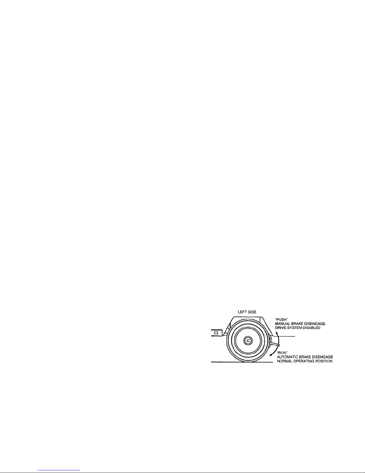
AUTOMATIC PARKING BRAKE OPERATION (CE Only):
Brake lever located behind left wheel.
Run Mode - Normal operation; Brake lever in down position.
• When the power is turned off the brake is automatically engaged.
• When the power is turned on the brake is automatically disengaged and the drive system is enabled.
Push Mode - Machine inoperable; Brake lever in up position.
• Brake is manually disengaged.
• Power is shut off to the drive system.
MAINTENANCE:
Daily
1. Clean float assembly & squeegee blades. Vac filter.
2. Recharge batteries (check battery acid levels before and after charging).
Monthly
1. Check wear on squeegee blades.
2. Grease rear wheels.
3. Grease pivot points on brush motor assembly.
5

MAINTENANCE OF MACHINE
VACUUM MOTOR
Motor brushes can be replaced with Brush Set, Part No. 741008. Brushes should be replaced only
once. More than once brush replacement will cause very high current consumption. This undue current consumption lowers overall machine performance and is not in the best interest of economical
machine use.
CARBON BRUSHES IN DRIVE MOTOR
Inspect these brushes once every 18 months or 720 hours.
The brushes can now be inspected by removing the brush caps near the end of the drive motor.
Examine all four brush lengths; if the back end of a brush is even with the edge of the brush holder or
shorter, the brush must be replaced. Replace with Brush Set, Part No. 744155. When installing new
brushes, also inspect cummutator for pits and/or excessive wear. If it is in poor condition, replace
drive motor with Part No. 744154.
CARBON BRUSHES IN BRUSH DRIVE MOTORS
Inspect these brushes once every six months or 360 hours.
Remove scrub head assembly. Examine brush lengths; if the back end of brush is even with the edge
of the brush holder or shorter, the brush must be replaced. Replace with Part No. 833474. When
installing new brushes, also inspect commutator for pits and/or excessive wear. Replace motor with
Part No. 742714 if commutator is in poor condition.
LUBRICATION
1. Grease casters once every week (two fittings per caster) or 15 hours.
2. Oil all moving parts such as hinges and pressure points once every month or every 60 hours.
SQUEEGEE RUBBERS
When the thick rear squeegee rubber is damaged or worn excessively, it will cause streaking and
poor solution pickup. Extended rubber life and be obtained by reversing it, provided it is not torn or
otherwise damaged. Do not tighten screws so tightly that squeegee rubbers are made to bulge and
show an uneven edge.
TANKS
At the end of a day’s work (or work cycle, both the vacuum and solution tanks should be drained and
flushed with warm water.
Once a week for 15 hours the vacuum tank should be cleaned of settled debris. This can be done by lowering the drain hose and
washing out the debris.
BATTERIES (956720, 956740)
Periodically remove batteries from machine. Clean batteries, battery tray, and battery compartment
with a solution of baking soda and water. Check all battery cables and wiring for signs of damage or
wear. Replace as needed. Check battery fluid level each charge. Check electrolyte with hydrometer
every 15 hours.
6
 Loading...