

Minuteman 260, MC260026CETD, MC260024QPBD, MC260024CEBD, MC260026QPTD Service Manual
260
Floor Scrubber
Traction Driven
Brush Driven
Model:Model:
Model:
Model:Model:
MC260024QPBDMC260024QPBD
MC260024QPBD
MC260024QPBDMC260024QPBD
MC260026QPTDMC260026QPTD
MC260026QPTD
MC260026QPTDMC260026QPTD
MC260024CEBDMC260024CEBD
MC260024CEBD
MC260024CEBDMC260024CEBD
MC260026CETDMC260026CETD
MC260026CETD
MC260026CETDMC260026CETD
OPERAOPERA
OPERA
OPERAOPERA
TIONTION
TION
TIONTION
SERVICESERVICE
SERVICE
SERVICESERVICE
PP
P
PP
ARAR
AR
ARAR
TSTS
TS
TSTS
CARECARE
CARE
CARECARE
Revised 9/05

TT
ABLE OF CONTENTSABLE OF CONTENTS
T
ABLE OF CONTENTS
TT
ABLE OF CONTENTSABLE OF CONTENTS
Safety Instructions .............................................................. 1
Electrical Requirements .................................................... 2
Control Panel Identification ................................................. 3
Squeegee Adjustments ...................................................... 4
Operating Instructions ........................................................5
Main Polyethylene Components .................................. 6 & 7
Recovery Tank and Solution Tank................................ 8 & 9
Drive Assemblies (Brush Driven) ............................. 10 & 11
Mainframe (Brush Driven) ....................................... 12 & 13
Console Assembly (Brush Driven) .......................... 14 & 15
Recovery Tank and Solution Tank............................ 16 & 17
Drive Assemblies (Traction Driven) ......................... 18 & 19
Mainframe (Traction Drive) ...................................... 20 & 21
Console Assembly (Traction Driven) ....................... 22 & 23
Squeegee Mechanism Assembly ..................................... 24
Squeegee Assembly Complete ........................................25
Wiring Diagram (Brush Driven) ........................................ 26
Wiring Diagram (Brush Driven, CE Model) ...................... 27
Wiring Diagram (Traction Driven)..................................... 28
Wiring Diagram (Traction Driven, CE Model) ...................29

IMPORIMPOR
IMPOR
IMPORIMPOR
CAUTIONCAUTION
CAUTION
CAUTIONCAUTION
Operators must read and understand this manual before operating or maintaining
this equipment.
• Keep hands and feet clear of moving parts while machine is in operation.
• All switches must be in the “OFF” position when charging batteries.
• Electrical motors and components can cause an explosion when operated near explosive materials
or vapors. Do not operate this machine near flammable materials such as solvents, thinners, fuels,
grain dusts, etc.
• Make sure all switches are turned “OFF” and battery connections are removed before performing
any maintenance procedures.
• Store or park this machine on a level surface only.
TT
ANTANT
T
ANT
TT
ANTANT
SAFETY SAFETY
SAFETY
SAFETY SAFETY
INSTRUCTIONS INSTRUCTIONS
INSTRUCTIONS
INSTRUCTIONS INSTRUCTIONS
• These machines are designed for level floor operation only. DO NOT OPERATE on ramps or
inclines.
• Battery acid can cause burns. When working on or around batteries, wear protective clothing and
safety glasses. Remove metal jewelry. Do not lay tools or metal objects on top of batteries.
• This machine is not suitable for picking up hazardous dust.
• Charging batteries generates explosive gases. DO NOT CHARGE BATTERIES WHEN OPEN
FLAMES OR SPARKS ARE PRESENT. DO NOT SMOKE. Make sure the charger is turned off
before disconnecting it from the batteries. Charge the batteries in a well-ventilated area.
• Maintenance and repairs must be performed by authorized personnel.
SASA
SA
SASA
VE VE
THESE INSTRUCTIONSTHESE INSTRUCTIONS
VE
THESE INSTRUCTIONS
VE VE
THESE INSTRUCTIONSTHESE INSTRUCTIONS
1
ELECTRICAL REQUIREMENTS:ELECTRICAL REQUIREMENTS:
ELECTRICAL REQUIREMENTS:
ELECTRICAL REQUIREMENTS:ELECTRICAL REQUIREMENTS:
This piece of equipment operates on 24 Volt DC.
BABA
BA
BABA
TTERTTER
TTER
TTERTTER
YY
REQUIREMENTS: REQUIREMENTS:
Y
REQUIREMENTS:
YY
REQUIREMENTS: REQUIREMENTS:
4 x 6V 220AH P/N 956720
4 x 6V 275AH P/N 956740
BABA
TTERTTER
BA
TTER
BABA
TTERTTER
**
* Warning: Battery acid can cause burns. When working on or around batteries, wear protective
**
YY
SER SER
Y
SER
YY
SER SER
VICE VICE
VICE
VICE VICE
AND INSTAND INST
AND INST
AND INSTAND INST
ALLAALLA
ALLA
ALLAALLA
TION:TION:
TION:
TION:TION:
clothing and safety glasses. Remove metal jewelry. Do not lay tools or metal objects on top of
batteries.
BABA
BA
BABA
TTERTTER
TTER
TTERTTER
YY
INST INST
Y
INST
YY
INST INST
ALLAALLA
ALLA
ALLAALLA
TION:TION:
TION:
TION:TION:
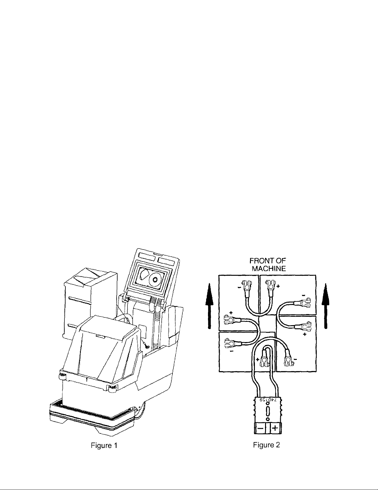
1. Disconnect tank drain hose from rear of machine (6).
2. Raise tank assembly by raising rear cover and tilting tank, Figure 1.
3. Install batteries as shown in Figure 2.
CHARGING OF BACHARGING OF BA
CHARGING OF BA
CHARGING OF BACHARGING OF BA
TTERIES:TTERIES:
TTERIES:
TTERIES:TTERIES:
Charging of batteries generates explosive gases. DO NOT CHARGE BATTERIES WHEN OPEN
FLAMES OR SPARKS ARE PRESENT. DO NOT SMOKE. Make sure the charger is turned off
before disconnecting it from the batteries. Charge the batteries in a well-ventilated area. Fluid levels
should be checked before and after charging and maintained at the proper levels.
2
CONTROLCONTROL
CONTROL
CONTROLCONTROL
P P
ANELANEL
P
ANEL
P P
ANELANEL
IDENTIFICA IDENTIFICA
IDENTIFICA
IDENTIFICA IDENTIFICA
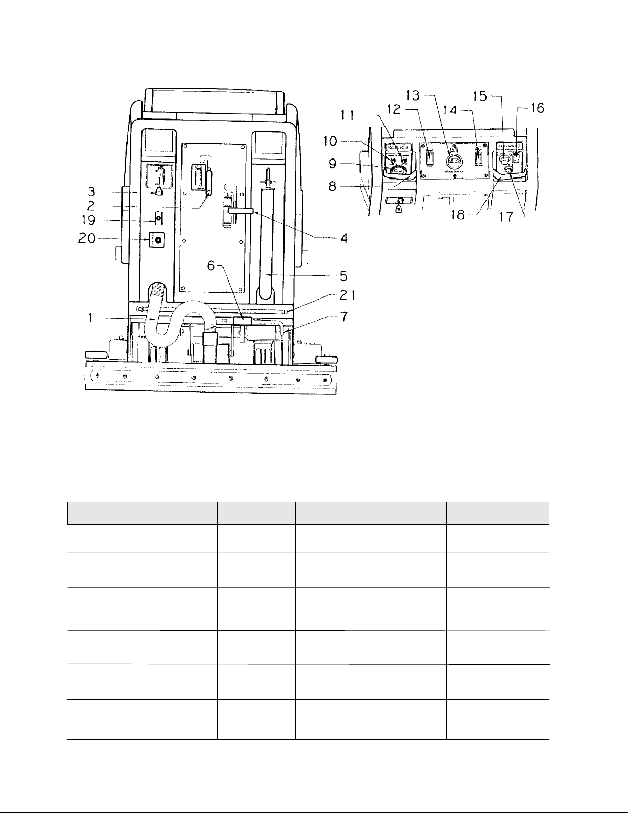
1. Vacuum recovery hose
2. Squeegee lift lever
3. Solution control lever
4. Brush pressure handle
5. Drain hose for recovery tank
6. Foot pedal for lower/raising brush
7. Drain hose for battery tray
8. Reverse control lever
9. Hour meter (optional)
10. Circuit breaker for vacuum motor
11. Circuit breaker for brush motor
12. Brush switch
13. Battery condition gauge
14. Vacuum switch
15. Speed control knob
16. Main power switch
17. Key switch (optional)
18. Forward control lever
19. Pump switch (optional)
20. Quick disconnect aux. out (optional)
21. Dump hose for solution tank
TIONTION
TION
TIONTION
AUTO SCRUBBER BRUSH DESCRIPTIONAUTO SCRUBBER BRUSH DESCRIPTION
AUTO SCRUBBER BRUSH DESCRIPTION
AUTO SCRUBBER BRUSH DESCRIPTIONAUTO SCRUBBER BRUSH DESCRIPTION
TYPE TYPE
TYPE
TYPE TYPE
Bassine Natural Fiber Short Dark Red Light duty
Nylon Nylon Medium Black Tan/Red General cleaning
Dyna-Scrub Nylon impregnated Long Light Red General scrubbing,
Power-Scrub Nylon impregnated Long Rust Red/Blue Moderate aggressive
Poly-Grit Nylon impregnated Long Green Brown/Black Aggressive stripping
Strata-Grit Nylon impregnated Long Dark Black Heavy duty
DESCRIPTION DESCRIPTION
DESCRIPTION
DESCRIPTION DESCRIPTION
with 500 Grit Blue vinyl tile, ceramic
Silicone Carbide tile, epoxy floors,
Fine Bristle, urethane finish,
Dense Fill uneven concrete floors
with 120 Grit Silicon scrubbing, tile floors
Carbide Fine Bristle, concrete floors
Dense Fill
with 80 Grit and scrubbing, tile
Silicon Carbide floors, unfinished
Coarse Bristle concrete floors
with 46 Grit Blue stripping/scrubbing
Silicon Carbide unfinshed
Coarse Bristle concrete
**
Durability is dependent on floor surface, chemicals used and proper care. Durability is dependent on floor surface, chemicals used and proper care.
*
Durability is dependent on floor surface, chemicals used and proper care.
Durability is dependent on floor surface, chemicals used and proper care. Durability is dependent on floor surface, chemicals used and proper care.
**
DURABILITY* DURABILITY*
DURABILITY*
DURABILITY* DURABILITY*
COLOR COLOR
COLOR
COLOR COLOR
Brown general cleaning,
COMP COMP
COMP
COMP COMP
TT
T
TT
ARISONARISON
ARISON
ARISONARISON
O PO P
ADSADS
O P
ADS
O PO P
ADSADS
RECOMMENDED RECOMMENDED
RECOMMENDED
RECOMMENDED RECOMMENDED
USE USE
USE
USE USE
acid etching
& scrubbing vinyl
floors, ceramic tile
& concrete floors
3
SQUEEGEE SQUEEGEE
SQUEEGEE
SQUEEGEE SQUEEGEE
ADJUSTMENTSADJUSTMENTS
ADJUSTMENTS
ADJUSTMENTSADJUSTMENTS
The squeegee set-up is pre-adjusted at the factory. Adjustments may be required to get optimum performance for
different floors and conditions.
Ensure that the scrubber is on a relatively flat surface. Ensure that the scrubber is on a relatively flat surface.
1.
Ensure that the scrubber is on a relatively flat surface.
Ensure that the scrubber is on a relatively flat surface. Ensure that the scrubber is on a relatively flat surface.
head assembly ofhead assembly of
head assembly of
head assembly ofhead assembly of
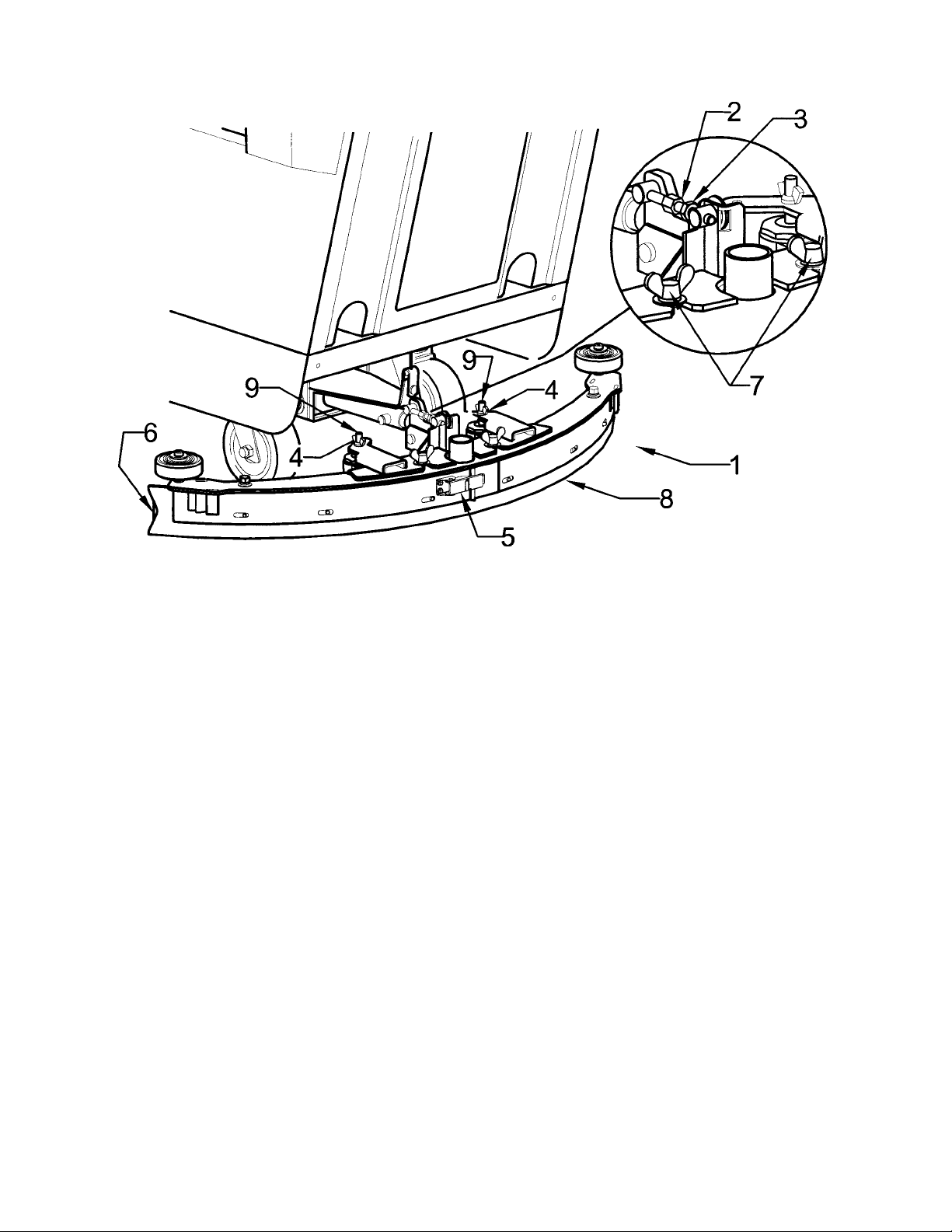
2. Turn the speed control knob counter-clockwise to the low speed position. Squeeze the forward control lever to lower
the squeegee (item 1) to the floor. Move the machine one or two feet forward to check the rear squeegee blade (item
8) for uniform deflection to the floor.
3. If uneven deflection or lay is evident, minor adjustments may be necessary to avoid streaking and uneven wear on
the blade.
4. To correct this, loosen the wing jam nut (item 4) in order to adjust the caster height. If the squeegee blade is
deflecting too much, the casters need to be lowered to control the down pressure. Lower the caster by turning the
exposed threaded stem (item 9) on the caster clockwise. Make the adjustment a few turns at a time.
5. Repeat step 2.
6. If the blades are not deflecting enough, raise the caster by turning the stem counter-clockwise to adjust the caster
hieght to allow more down pressure on the squeegee. Repeat Step 2.
7. Make sure that there is an even deflection on the entire length of the rear blade. Adjust the castors and retighten the
wing jam nuts to lockthe caster setting in place.
8. Pitch adjustment is necessary if the outer ends on the squeegee blade does not contact the floor and there is too
much deflection in the middle area or if the outer ends are over deflected and there is no contact in the middle.
9. To adjust pitch, lower the squeegee to the floor. Loosen the lock nut (item 3) in the turnbuckle assembly. Turning
the turnbuckle (item 2) clockwise or counterclockwise controls the forward and backward pitch of the squeegee.
Having the rear blades deflected uniformly along its entire length is the desired setup.
10. Repeat Step 2 until the desired setup is achieved.
11. In certain applications where a non-slotted front wiper blade (item 6) is needed, detach the squeegee assembly by
loosening the wing bolts (item7). Unlock the clamp on the front squeegee to release the straps and flip the blade
over to the non-slotted side. Reattach straps and lock the clamp back in place.
12. You can also easily replace the rear blade by unlatching the latch (item 5) and removing the straps by sliding them
off the assembly.
f the floorf the floor
f the floor
f the floorf the floor
. Set the squeegee/ vacuum switch to the automatic mode.. Set the squeegee/ vacuum switch to the automatic mode.
. Set the squeegee/ vacuum switch to the automatic mode.
. Set the squeegee/ vacuum switch to the automatic mode.. Set the squeegee/ vacuum switch to the automatic mode.
TT
urn on the main power switch and raise the scruburn on the main power switch and raise the scrub
T
urn on the main power switch and raise the scrub
TT
urn on the main power switch and raise the scruburn on the main power switch and raise the scrub
4

OPERAOPERA
OPERA
OPERAOPERA
1. Filling: Fill the solution tank with the desired amount of water and add liquid cleaning solution to
the proper dilution ratio. DO NOT USE powdered cleaning chemicals. Powders are unlikely to
dissolve thoroughly, resulting in clogging the in-line solution filter. This can reduce or stop water
flow to the brush.
2. Close lid.
3. Turn on main power switch (refer to Page 3, #16). (Traction Drive Only)
4. Adjust main speed control, #15 to full counter-clockwise position. (Traction Drive Only)
5. Lower brush assembly:
• Depress foot pedal (6) slightly and push in on lever (4) to release, to increase brush pressure
pull up and back on lever (4) to lock in position.
• To lift the brush, press the pedal down until lift mechanism engages.
6. Turn on brush switch.
7. Adjust solution control feed lever.
8. Select vacuum operation:
Brush Driven Models – Turn vacuum switch to “On” position Traction Driven Models
a) “Vacuum On” mode – Vacuum will remain on until switched to the “off” position
b) “Vacuum Auto” mode – Vacuum will come on automatically when forward or reverse handles
are squeezed, and remain on approximately 5 seconds after handle release.
TING INSTRUCTIONSTING INSTRUCTIONS
TING INSTRUCTIONS
TING INSTRUCTIONSTING INSTRUCTIONS
9. Lower squeegee assembly.
10. Squeeze forward handle #18 and adjust forward speed. (Traction Drive Only)
After Use:
1. Turn off solution feed.
2. Switch off brush and raise.
3. Raise squeegee assembly.
4. Turn off vacuum motor.
5. Solution and recovery tanks should be emptied after every use.
MAINTENANCE:MAINTENANCE:
MAINTENANCE:
MAINTENANCE:MAINTENANCE:
Daily
1. Clean float assembly & squeegee blades.
2. Recharge batteries (check battery acid levels before and after charging).
Monthly
1. Check wear on squeegee blades.
2. Grease front and rear wheels.
3. Grease pivot points on brush motor assembly.
Every 500 hours check condition of carbon brushes on vacuum motor and brush drive motor.
5
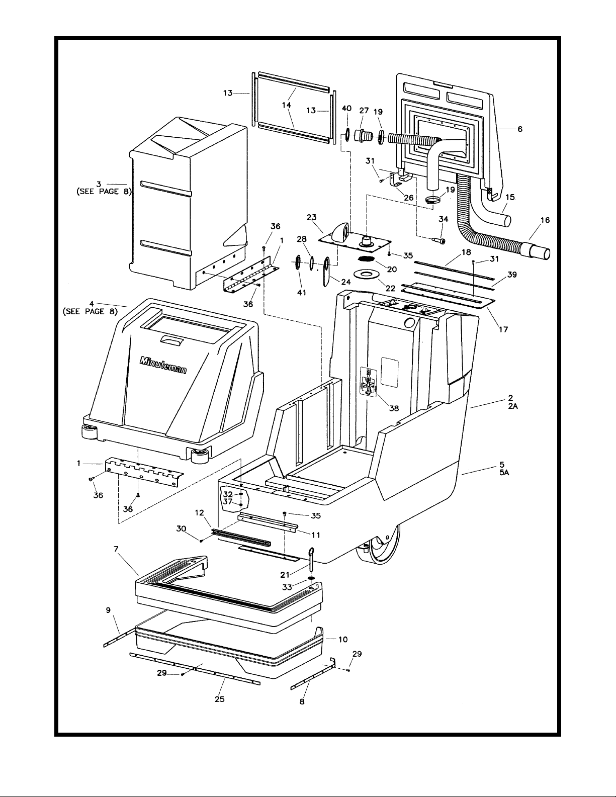
6

PartPart
Part
PartPart
s Lists List
s List
s Lists List
ItemItem
Item
ItemItem
10 260145 1 Splash Skirt
11 260148 1 Solution Dump Bracket 14GA
12 260149 1 U Channel 12”
13 260157 2 Lid Gasket Short 260B
14 260158 2 Lid Gasket 260B
15 260159 1 Hose Vac 1.5 x 78” Wireloc
16 260160 1 Recovery Hose Assy. 260B
17 260169 1 Lid Flap
18 260170 2 Retainer Strip
19 260203 2 Clamp Hose 102120 Murray
20 260212 1 Screen Filter
21 260241 2 Pin Hitch 7/16 x 3
22 260294 1 Gasket 260
23 260299 1 Shut-Off Plate Assy.
24 260301 1 Deflector Flap
25 260336 1 Skirt Retainer - Front
26 260353 2 Lid Pivot Strap
27 450037 1 Adapter MCH
28 450081 1 WSR-1.908 x 2.41 x .03 SS
29 711106 20 SCR-ST-A 10 x .75 PL
30 711124 2 SCR-ST-B 10 x .37 NI
31 711161 10 SCR-Hi/Lo #10 x 3/4 Zinc
32 711505 4 WSR-Flat 1/4
33 711508 2 WSR-Flat .44 x 1.00 x .08
34 712102 2 Bolt - Shoulder 1/2 x 1.5
35 712540 14 SCR-MC 10-24 x .37 SS TH
36 712565 17 SCR-MC 1/4-20 x .62 SS
37 712667 4 Nut-Nyloc 1/4-20 SS
38 715607 1 Decal - Battery Cable Rout
39 760263 2 Foam Tape 1/16 x 1/2
40 828970 1 WSR-Neop 1.87 x 2.4 x .125
41 828971 1 Nut - 1 1/2 Pipe Thread
Part No.Part No.
Part No.
Part No.Part No.
1 260087 2 Hinge 15”
2 260090 1 Rear Base Char Grey
2A 260256 1 Rear Base 260TD Char Grey
3 260091 1 Recovery Tank 260 Light Grey
4 260092 1 Solution Tank 260 Light Grey
5 260093 1 Chassis MMN 260
5A 260360 1 Mainframe MMN 260TD
6 260096B 1 Lid Recovery 260 Burgundy
7 260098 1 Front Skirt 260 Black
8 260142 1 Skirt Retainer L.H.
9 260143 1 Skirt Retainer R.H.
QtyQty
Qty
QtyQty
..
DescriptionDescription
.
Description
..
DescriptionDescription
7
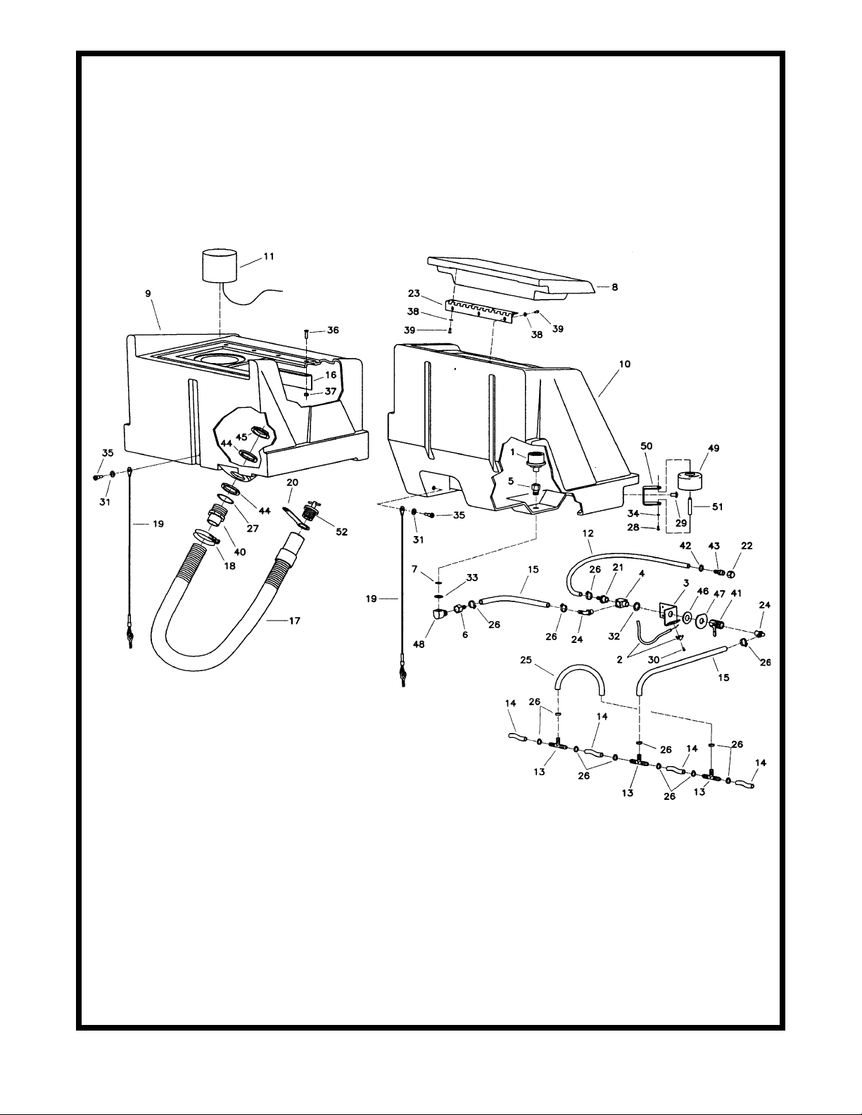
Brush DrivenBrush Driven
Brush Driven
Brush DrivenBrush Driven
8
 Loading...