

Minuteman 260, MC260024QP, MC260026QP, MC260024CE, MC260026CE Service Manual

260
Model:
Floor Scrubber
Traction Driven
Brush Driven
OPERATION
SERVICE PARTS
MC260024QP
MC260026QP
MC260024CE
MC260026CE
CARE
Revised 8/03
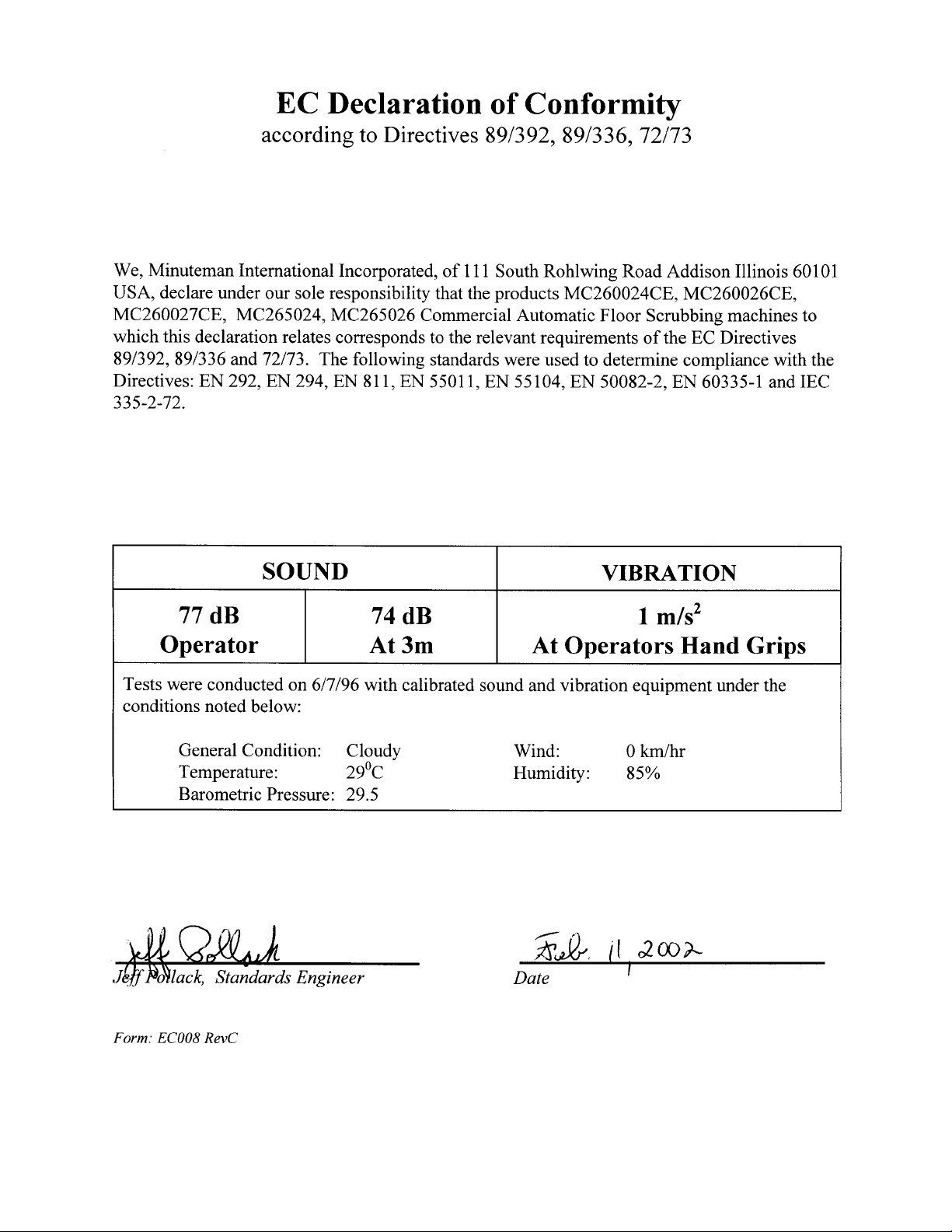

TABLE OF CONTENTS
Page
Safety Instructions 1
Electrical Requirements 2
Control Panel Identification 3
Squeegee Adjustments 4
Operating Instructions 5
Main Polyethylene Components 6 & 7
Recovery Tank and Solution Tank 8 & 9
Drive Assemblies (Brush Driven) 10 & 11
Mainframe (Brush Driven) 12 & 13
Console Assembly (Brush Driven) 14 & 15
Recovery Tank and Solution Tank 16 & 17
Drive Assemblies (Traction Driven) 18 & 19
Mainframe (Traction Drive) 20 & 21
Console Assembly (Traction Driven) 22 & 23
Squeegee Mechanism Assembly 24
Squeegee Assembly Complete 25
Wiring Diagram (Brush Driven) 26
Wiring Diagram (Brush Driven, CE Model) 27
Wiring Diagram (Traction Driven) 28
Wiring Diagram (Traction Driven, CE Model) 29

IMPORTANT SAFETY INSTRUCTIONS
CAUTION
Operators must read and understand this manual before operating or maintaining
this equipment.
• Keep hands and feet clear of moving parts while machine is in operation.
• All switches must be in the “OFF” position when charging batteries.
• Electrical motors and components can cause an explosion when operated near explosive materials
or vapors. Do not operate this machine near flammable materials such as solvents, thinners, fuels,
grain dusts, etc.
• Make sure all switches are turned “OFF” and battery connections are removed before performing
any maintenance procedures.
• Store or park this machine on a level surface only.
• These machines are designed for level floor operation only. DO NOT OPERATE on ramps or
inclines.
• Battery acid can cause burns. When working on or around batteries, wear protective clothing and
safety glasses. Remove metal jewelry. Do not lay tools or metal objects on top of batteries.
• This machine is not suitable for picking up hazardous dust.
• Charging batteries generates explosive gases. DO NOT CHARGE BATTERIES WHEN OPEN
FLAMES OR SPARKS ARE PRESENT. DO NOT SMOKE. Make sure the charger is turned off
before disconnecting it from the batteries. Charge the batteries in a well-ventilated area.
• Maintenance and repairs must be performed by authorized personnel.
SAVE THESE INSTRUCTIONS
1
ELECTRICAL REQUIREMENTS:
This piece of equipment operates on 24 Volt DC.
BATTERY REQUIREMENTS:
4 x 6V 220AH P/N 956720
4 x 6V 275AH P/N 956740
BATTERY SERVICE AND INSTALLATION:
* Warning: Battery acid can cause burns. When working on or around batteries, wear protective
clothing and safety glasses. Remove metal jewelry. Do not lay tools or metal objects on top of
batteries.
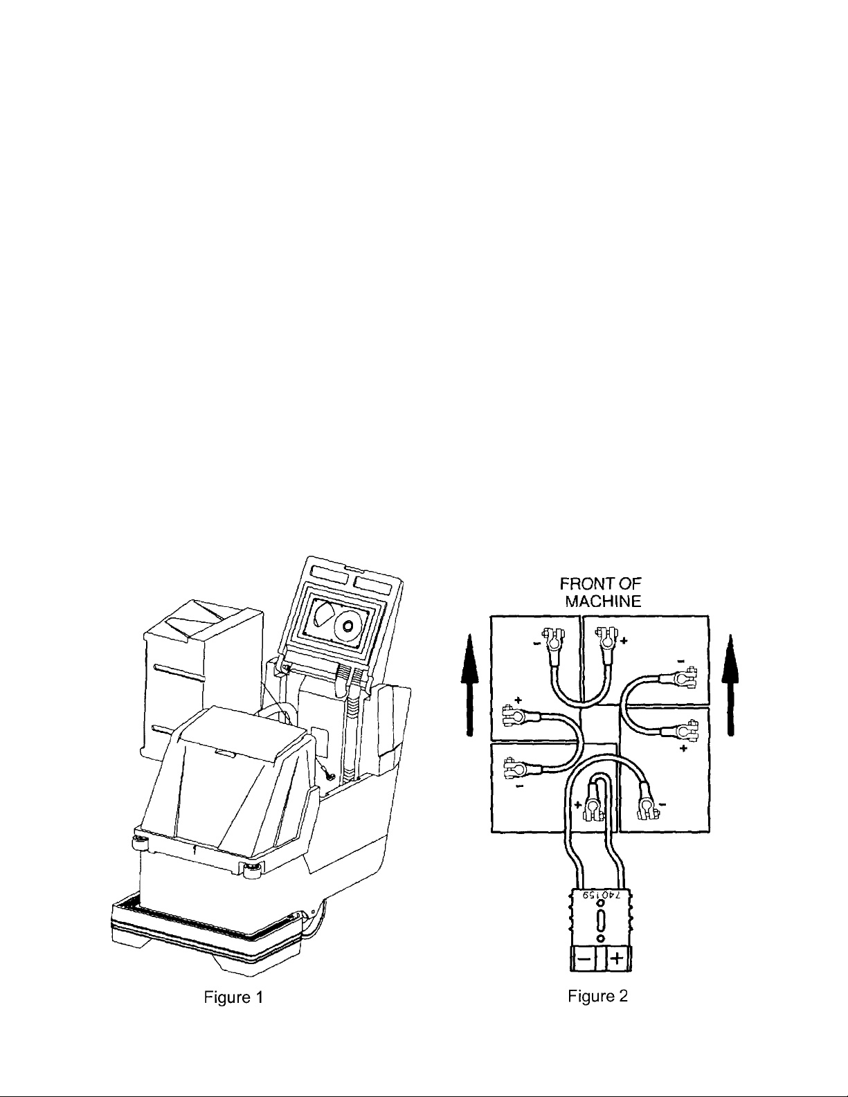
BATTERY INSTALLATION:
1. Disconnect tank drain hose from rear of machine (6).
2. Raise tank assembly by raising rear cover and tilting tank, Figure 1.
3. Install batteries as shown in Figure 2.
CHARGING OF BATTERIES:
Charging of batteries generates explosive gases. DO NOT CHARGE BATTERIES WHEN OPEN
FLAMES OR SPARKS ARE PRESENT. DO NOT SMOKE. Make sure the charger is turned off
before disconnecting it from the batteries. Charge the batteries in a well-ventilated area. Fluid levels
should be checked before and after charging and maintained at the proper levels.
2
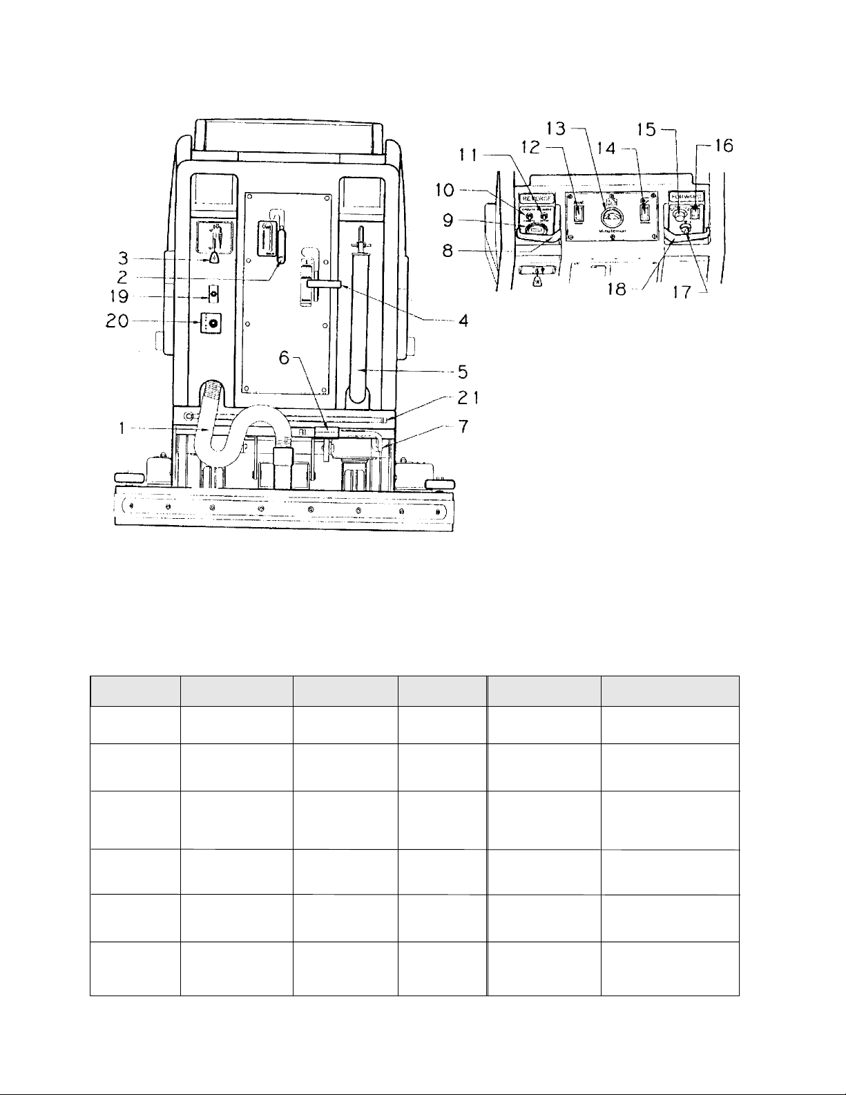
CONTROL PANEL IDENTIFICATION
1. Vacuum recovery hose
2. Squeegee lift lever
3. Solution control lever
4. Brush pressure handle
5. Drain hose for recovery tank
6. Foot pedal for lower/raising brush
7. Drain hose for battery tray
8. Reverse control lever
9. Hour meter (optional)
10. Circuit breaker for vacuum motor
11. Circuit breaker for brush motor
12. Brush switch
13. Battery condition gauge
14. Vacuum switch
15. Speed control knob
16. Main power switch
17. Key switch (optional)
18. Forward control lever
19. Pump switch (optional)
20. Quick disconnect aux. out (optional)
21. Dump hose for solution tank
AUTO SCRUBBER BRUSH DESCRIPTION
TYPE DESCRIPTION DURABILITY* COLOR COMPARISON RECOMMENDED
TO PADS USE
Bassine Natural Fiber Short Dark Red Light duty
Nylon Nylon Medium Black Tan/Red General cleaning
Dyna-Scrub Nylon impregnated Long Light Red General scrubbing,
with 500 Grit Blue vinyl tile, ceramic
Silicone Carbide tile, epoxy floors,
Fine Bristle, urethane finish,
Dense Fill uneven concrete floors
Power-Scrub Nylon impregnated Long Rust Red/Blue Moderate aggressive
with 120 Grit Silicon scrubbing, tile floors
Carbide Fine Bristle, concrete floors
Dense Fill
Poly-Grit Nylon impregnated Long Green Brown/Black Aggressive stripping
with 80 Grit and scrubbing, tile
Silicon Carbide floors, unfinished
Coarse Bristle concrete floors
Strata-Grit Nylon impregnated Long Dark Black Heavy duty
with 46 Grit Blue stripping/scrubbing
Silicon Carbide unfinshed
Coarse Bristle concrete
Brown general cleaning,
acid etching
& scrubbing vinyl
floors, ceramic tile
& concrete floors
* Durability is dependent on floor surface, chemicals used and proper care.
3
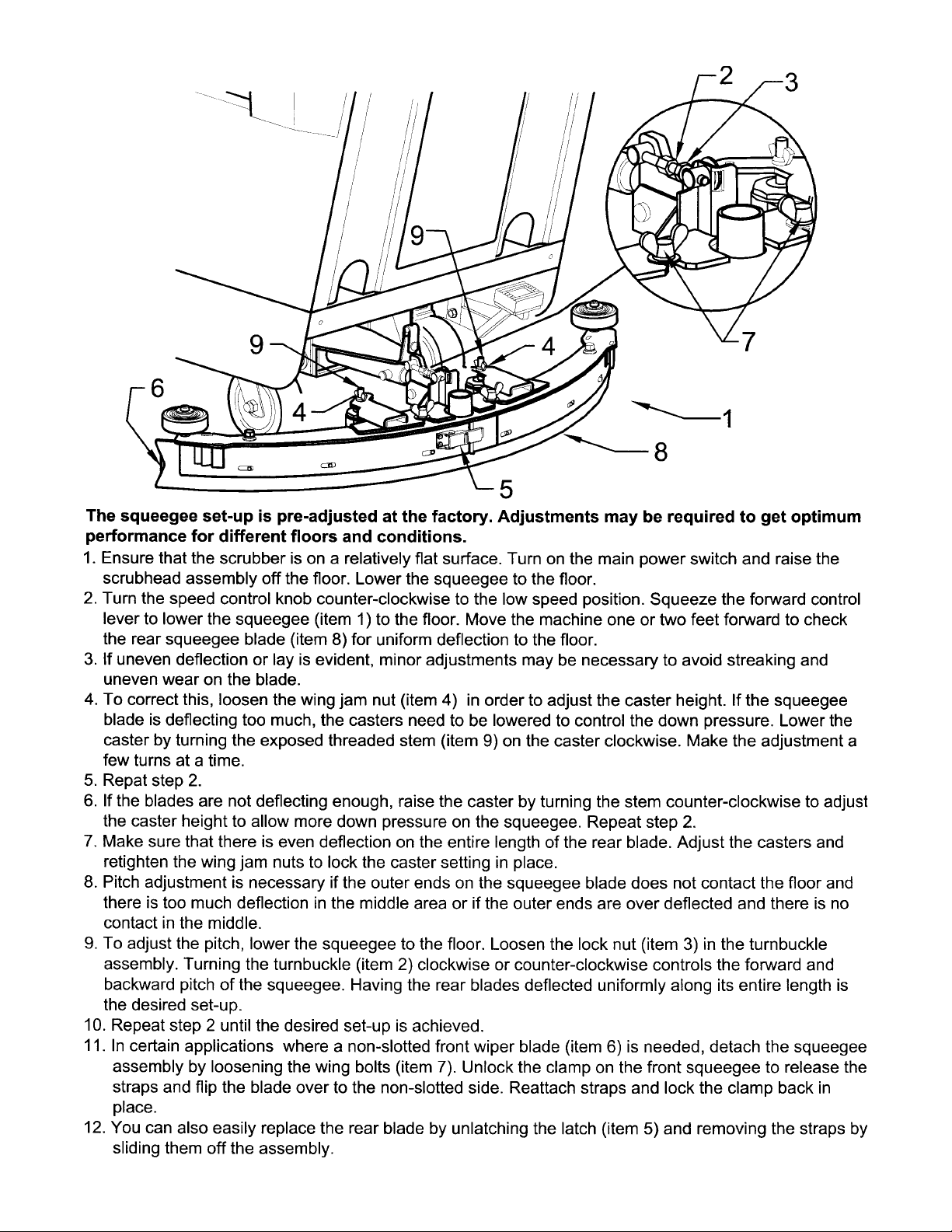
SQUEEGEE ADJUSTMENTS
4

OPERATING INSTRUCTIONS
1. Filling: Fill the solution tank with the desired amount of water and add liquid cleaning solution to
the proper dilution ratio. DO NOT USE powdered cleaning chemicals. Powders are unlikely to
dissolve thoroughly, resulting in clogging the in-line solution filter. This can reduce or stop water
flow to the brush.
2. Close lid.
3. Turn on main power switch (refer to Page 3, #16). (Traction Drive Only)
4. Adjust main speed control, #15 to full counter-clockwise position. (Traction Drive Only)
5. Lower brush assembly:
• Depress foot pedal (7) slightly and push in on lever (5) to release, to increase brush pressure
pull up and back on lever (5) to lock in position.
• To lift the brush, press the pedal down until lift mechanism engages.
6. Turn on brush switch.
7. Adjust solution control feed lever.
8. Select vacuum operation:
Brush Driven Models – Turn vacuum switch to “On” position Traction Driven Models
a) “Vacuum On” mode – Vacuum will remain on until switched to the “off” position
b) “Vacuum Auto” mode – Vacuum will come on automatically when forward or reverse handles
are squeezed, and remain on approximately 5 seconds after handle release.
9. Lower squeegee assembly.
10. Squeeze forward handle #18 and adjust forward speed. (Traction Drive Only)
After Use:
1. Turn off solution feed.
2. Switch off brush and raise.
3. Raise squeegee assembly.
4. Turn off vacuum motor.
5. Solution and recovery tanks should be emptied after every use.
MAINTENANCE:
Daily
1. Clean float assembly & squeegee blades.
2. Recharge batteries (check battery acid levels before and after charging).
Monthly
1. Check wear on squeegee blades.
2. Grease front and rear wheels.
3. Grease pivot points on brush motor assembly.
Every 500 hours check condition of carbon brushes on vacuum motor and brush drive motor.
5
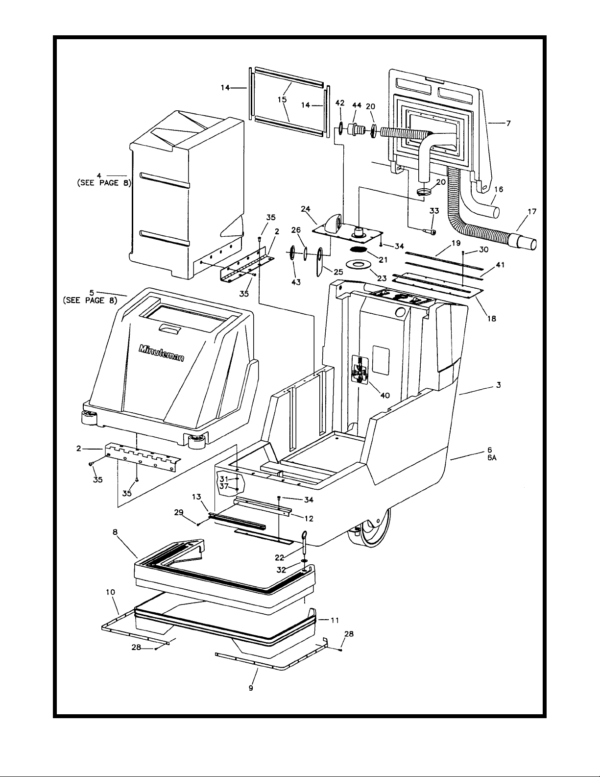
6

Parts List
Item Part No. Qty. Description
1
2 260087 2 Hinge 15”
3 260090 1 Rear Base
4 260091 1 Recovery Tank
5 260092 1 Solution Tank
6 260093 1 Mainframe Weldment - BD
6A 260375 1 Mainframe Weldment - TD
7 260096B 1 Recovery Lid
8 260098 1 Front Skirt
9 260142 1 Skirt Retainer L.H.
10 260143 1 Skirt Retainer R.H.
11 260145 1 Splash Skirt
12 260148 1 Solution Dump Bracket
13 260149 1 U Channel 12”
14 260157 2 Lid Gasket Short
15 260158 2 Lid Gasket Long
16 260159 1 Vac Hose - White
17 260160 1 Recovery Hose Assy.
18 260169 1 Lid Flap
19 260170 2 Retainer Strip
20 260203 2 Hose Clamp, Wire Grip
21 260212 1 Screen Filter
22 260241 2 Hitch Pin 7/16 x 3”
23 260294 1 Gasket
24 260299 1 Shut-Off Plate Assy.
25 260301 1 Deflector Flap
26 450081 1 WSR-1.904 x 2.41 x .03 SS
27
28 711106 20 SCR-ST-A 10 x .75 PL
29 711124 2 SCR-ST-B 10 x .37
30 711161 10 SCR-Hi/Lo 10 x 5/8
31 711505 4 WSR-Flat ¼
32 711508 2 WSR-Flat 7/16
33 712102 2 Bolt - Shoulder ½ x 1.50
34 712540 14 SCR-MC 10-24 x .37 SS TH
35 712565 17 SCR-MC ¼-20 x .62 SS
36
37 712667 4 Nut-Nyloc ¼-20
38
39
40 715607 1 Decal - Battery Routing
41 760263 2 Foam Tape 16.50”
42 828970 1 WSR-Neop 1.87 x 2.4 x .125
43 828971 1 Nut - 1 ½ Pipe Thread
44 450037 1 Adapter MCH
7
 Loading...