

Minuteman MC240024QP Service Manual
240X
Model:
Floor Scrubber
Battery
OPERATION
SERVICE PARTS
MC240024QP, CE
CARE
Revised 8/02

Table of Contents
Safety instructions................................................ 1
Electrical requirements ........................................ 2
Control panel identification................................... 3
Operating instructions .......................................... 4
Squeegee adjustments........................................ 5
Brush installation/removal .................................... 6
Base assembly .................................................... 7 - 8
Tank assembly ..................................................... 9 - 10
Upper assembly ...................................................11
Console assembly ...............................................12
Motor lift assembly ............................................... 13 - 14
Scrudhead assembly ...........................................15 - 16
Casting assembly ................................................ 17
Motor assembly ................................................... 18
Dashboard & back panel assembly ..................... 19
Squeegee lift & Squeegee mechanism .............. 20
Plastic housing assembly .................................... 21
Squeegee assembly............................................ 22
Wiring diagram, standard ..................................... 23 - 24
Wiring diagram, CE ..............................................24 – 25
Warranty ............................................................... Back Cover

IMPORTANT SAFETY INSTRUCTIONS
CAUTION
Operators must read and understand this manual before operating or maintaining this equipment.
• Keep hands and feet clear of moving parts while machine is in operation.
• All switches must be in the “OFF” position when charging batteries.
• Electrical motors and components can cause an explosion when operated near explosive
materials or vapors. Do not operate this machine nearflammable materials such as solvents,
thinners, fuels, grain dusts, etc.
• Make sure all switches are turned “OFF” and battery connections are removed before
performing any maintenance procedures.
• Store or park this machine on a level surface only.
• These machines are designed for level floor operation only. DO NOT OPERATE on ramps
or inclines.
• Battery acid can cause burns. When working on or around batteries, wear protective clothing
and safety glasses. Remove metal jewelry. Do not laytools or metal objects on top of
batteries.
• This machine is not suitable for picking up hazardous dust.
Charging batteries generates explosive gases. DO NOT CHARGE BATTERIES WHEN OPEN
FLAMES OR SPARKS ARE PRESENT. DO NOT SMOKE. Make sure the charger is turned off
before disconnecting it from the batteries. Charge the batteries in a well-ventilated area.
Maintenance and repairs must be performed by authorized personnel.
SAVE THESE INSTRUCTIONS
1
ELECTRICAL REQUIREMENTS:
This piece of equipment operates on 24 Volt DC.
BATTERY REQUIREMENTS:
2 x 12V 210 Amp Hour 20 Hour Rate Deepcycle P/N 956210
BATTERY SERVICE AND INSTALLATION:
Warning: Battery acid can cause burns. When working on or around batteries, wear protective clothing
and safety glasses. Remove metal jewelry. Do not lay tools or metal objects on top of batteries.
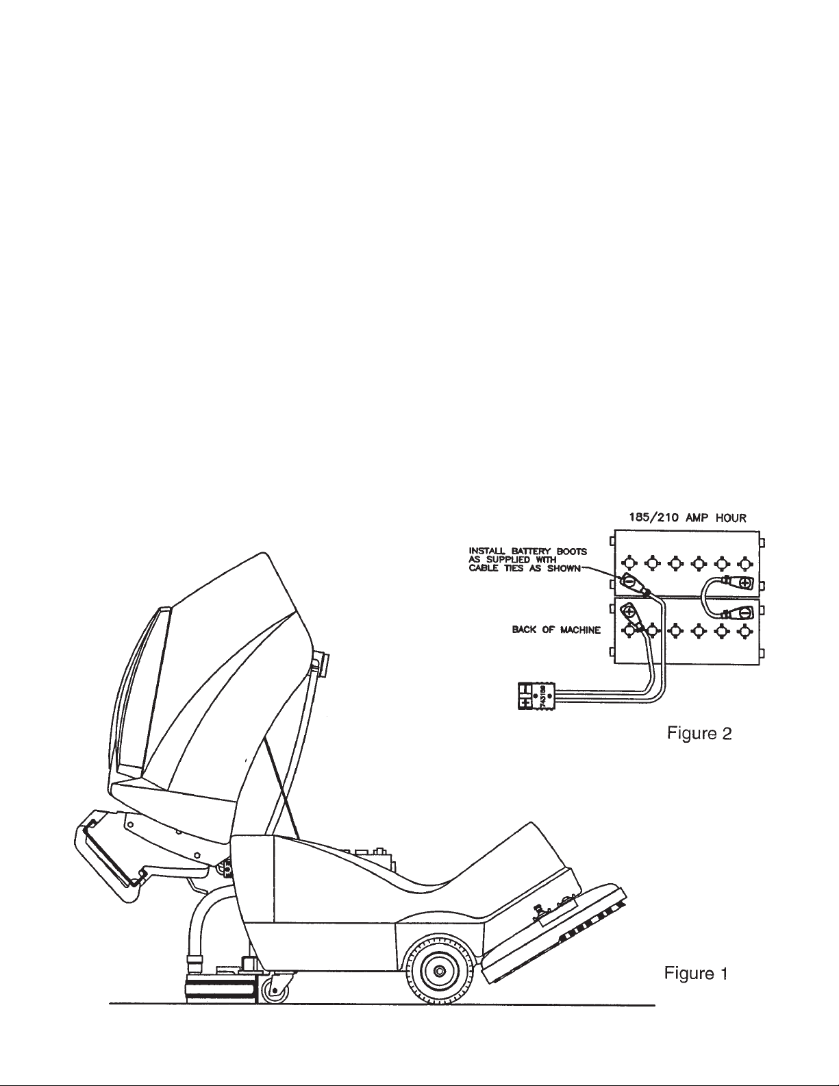
BATTERY INSTALLATION:
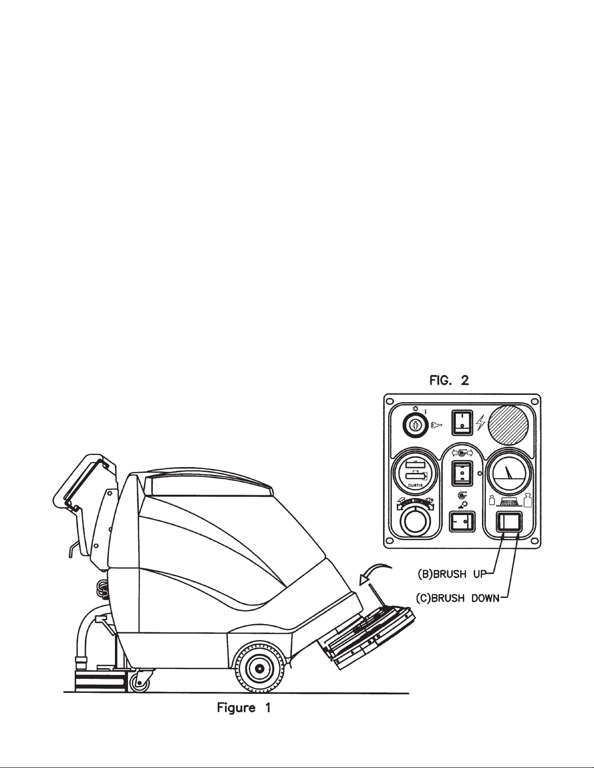
1. Raise tank assembly by gripping the front of tank and lift tank backward as shown in Fig. 1.
2. Install batteries as shown in Figure 2.
CHARGING OF BATTERIES:
Charging of batteries generates explosive gases. DO NOT CHARGE BATTERIES WHEN OPEN
FLAMES OR SPARKS ARE PRESENT. DO NOT SMOKE. Make sure the charger is turned off
before disconnecting it from the batteries. Charge the batteries in a well-ventilated area. Fluid levels
should be checked before and after charging and maintained at the proper levels.
2
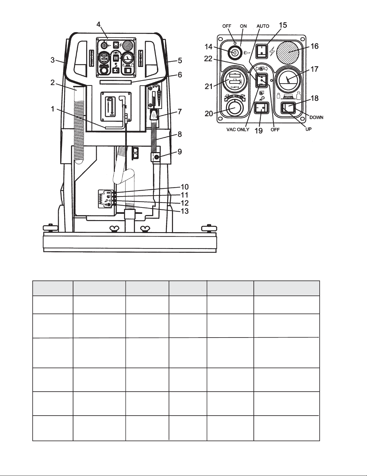
AUTO SCRUBBER BRUSH DESCRIPTION
1. Squeegee lift lever
2. Recovery dump hose
3. Reverse handle
4. Dashboard control panel
5. Forward handle
6. Safety bar switch
7. Solution control lever
8. Solution dump hose
9. Quick disconnect - Aux. out (Deluxe only)
10. Circuit breaker - Brush
11. Circuit breaker - Vac
12. Circuit breaker - System
13. Circuit breaker - Transaxle
14. Keyswitch
15. Main power
16. Emergency button
17. Brush pressure gauge
18. Brush control
19. Pump switch
20. Speed control
21. Battery condition meter
22. Vacuum control switch
TYPE DESCRIPTION DURABILITY* COLOR TO PADS USE
Bassine Natural Fiber Short Dark Brown Red Light duty
Nylon Nylon Medium Black Tan/Red General cleaning
Dyna-Scrub Nylon impregnated Long Light Red General scrubbing,
with 500 Grit vinyl tile, ceramic
Silicon Carbide tile, epoxy floors,
Fine Bristle, urethane finish,
Power-Scrub Nylon impregnated Long Rust Red/Blue Moderate aggressive
Poly-Grit Nylon impregnated Long Green Brown/Black Aggressive stripping
Strata-Grit Nylon impregnated Long Dark Blue Black Heavy duty
Dense Fill
with 120 Grit Silicon scrubbing, tile floors,
Carbide Fine Bristle, concrete floors
Dense Fill
with 80 Grit and scrubbing, tile
Silicon Carbide floors, unfinished
Coarse Bristle concrete floors
with 46 Grit stripping/scrubbing
Silicon Carbide
Coarse Bristle
••
•
Durability is dependent on floor surface, chemicals used and proper care.
••
COMPARISON RECOMMENDED
general cleaning,
acid etching
& scrubbing vinyl
floors, ceramic tile
& concrete floors
uneven concrete floors
unfinished concrete
3

OPERATING INSTRUCTIONS
BEFORE STARTING, FAMILIARIZE YOURSELF WITH THE MACHINE AND ITS CONTROLS
(SEE MACHINE OVERVIEW & CONTROL PANEL DIAGRAMS)
1. Filling: Fill the solution tank with the desired amount of water and add liquid cleaning solution to
the proper dilution ratio. DO NOT USE powdered cleaning chemicals. Powders are unlikely to
dissolve thoroughly, resulting in clogging the in-line solution filter. This can reduce or stop
water flow to the brush.
2. Close lid.
3. Turn on machine by lifting the red emergency disconnect button (17) so it is in the up position.
Turn keyswitch (15) clockwise to “on” position and turn on main power switch (16).
4. Adjust main speed control (21) to full counter-clockwise position.
5. Lower brush assembly.
- To lower the brush, first push the pedal (10) slightly outward on the machine (unlock it), and
then release it slowly or by pressing “brush down” switch (19) on Deluxe models.
- To lift the brush, press the pedal (10) down until lift mechanism engages or by pressing
”brush up” switch (19) on Deluxe models.
- Brush will come on automatically when brush in on the floor and “forward” (5) or “reverse” (3)
handles are squeezed and remain on approximately 5 seconds after release.
6. Adjust solution control feed lever.
7. Select vacuum operations:
- “Vacuum On” mode (23) - Vacuum will remain on until switched to the “off” position
- “Vacuum Auto” mode (23) - Vacuum will come on automatically when “forward” or
“reverse” handle is squeezed, and scrubhead is on the floor. The brush and vacuum
will remain on approximately 5 minutes.
8. Lower squeegee assembly by lowering handle (1).
9. Squeeze “forward” handle (5) and adjust forward speed (21) as desired.
After Use:
1. Turn off solution feed.
2. Raise squeegee assembly.
3. Turn off vacuum motor.
Solution and recovery tanks should be emptied after every use.
MAINTENANCE:
Daily 1. Clean float assembly & squeegee blades. Vac filter
2. Recharge batteries (check battery acid levels before and after charging).
Monthly 1. Check wear on squeegee blades.
2. Grease front wheels.
3. Grease pivot points on brush motor assembly.
Every 500 hours check condition of carbon brushes on vacuum motor and brush drive motor.
4
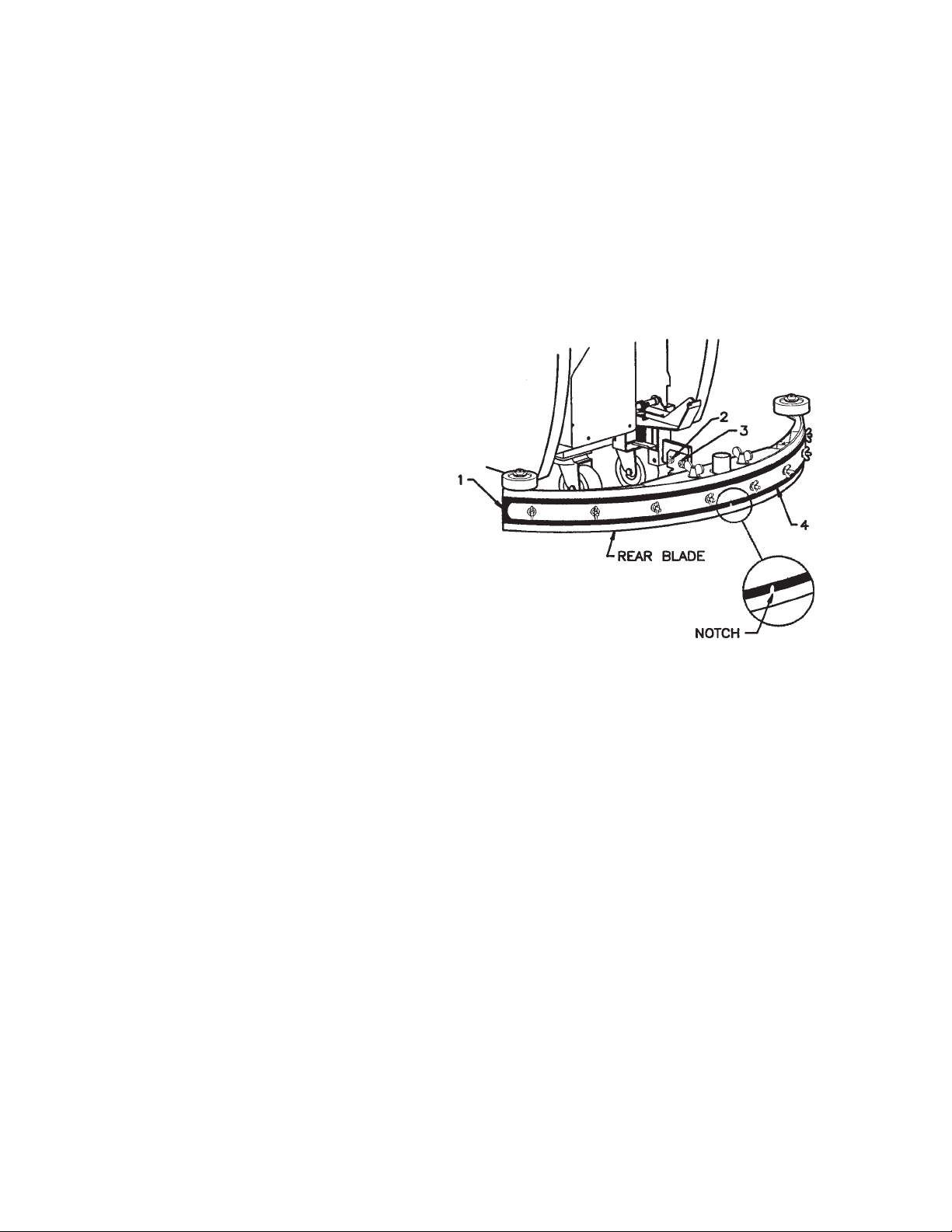
SQUEEGEE ADJUSTMENTS
Squeegee Adjustment
The squeegee set-up is pre-adjusted at the factory. Adjustments may be required to get optimum
performance for different floors and conditions.
Pitch Control Adjustment
1. Ensure that the scrubber is on a
relatively flat surface. Pull the red
emergency button away from the
dashboard to activate power. Turn on the
main power switch and turn the key
switch clockwise to the on position.
Raise the scrubhead off the floor. Turn
the vacuum switch to the “vacuum only”
position.
2. Turn the speed control knob counterclockwise to the low speed position.
Lower the squeegee (item 1) to the floor
and squeeze the forward control handle,
move the machine one or two feet
forward to check the rear squeegee
blade for uniform deflection to the floor.
3. If uneven deflection or lay is evident, minor adjustments may be necessary to avoid streaking and
uneven wear on the blade.
4. To correct this, pitch adjustment is necessary. Loosen the pivot screw (item 2) and the pitch
screw (item 3). Move the machine forward and allow the squeegee to level itself or adjust the
angular position accordingly to achieve a uniform blade deflection. Re-tighten screws.
5. In certain applications where a different blade set-up is required, the reinforcement blade (item
4) may be turned upside down. The notch, which is normally on the bottom will now be located on
the topside. This allows the rear squeegee blade a larger deflection than normal.
5
BRUSH INSTALLATION - REMOVAL
INSTALLATION
1. Raise the scrubhead to the “UP” position by pressing the switch “BRUSH UP” (B) switch as
shown on Fig. 2 until the scrubhead stops retracting upwards.
2. Hold brush under the scrubhead casting while lining up the center of brush with the hex drive
hub and pressing the brush up until the brush engages on the hub.
REMOVAL
1. Raise the scrubhead to the “UP” position by pressing the switch “BRUSH UP” (B) switch as
shown on Fig. 2 until the scrubhead stops retracting upwards.
2. Flip the handle up (Fig. 1) located at the middle of the plastic shroud. Push the handle towards
the machine and the bracket underneath the casting will release both brushes at once. Replace
handle in parked position.
6
 Loading...