

Page 1

200X
Model: MC20003QP
Brush Drive
Floor Scrubber
Electric
OPERATION
SERVICE PARTS
MC20004CE
CARE
Revised 6/02
Page 2

TABLE OF CONTENTS
Page
Safety Instructions 1
Electrical Requirements 2
Control Panel Identification 3
Operating Instructions 4
Squeegee Adjustments 5
Brush Installation/Removal 6
Base Assembly 7 & 8
Tank Assembly 9 & 10
Upper Assembly 11
Console Assembly 12
Motor Lift Assembly 13
Scrubhead Assembly 14
Back Panel Assembly 15
Squeegee Lift & Mechanism Assembly 16
Squeegee Assembly Complete 17
Wiring Diagram, 115V 18
Wiring Diagram, 230V CE 19
Page 3

Page 4

FOR COMMERCIAL USE ONLY
IMPORTANT SAFETY INSTRUCTIONS
When using an electrical appliance, basic precautions should always be followed, including the
following:
READ ALL INSTRUCTIONS BEFORE USING
WARNING - To reduce the risk of fire, electric shock, or injury:
• Do not leave appliance when plugged in. Unplug from outlet when not
in use and before servicing, cleaning or maintaining.
WARNING
To reduce the risk of electric shock - Do not expose to rain. Store indoors.
• Do not allow to be used as a toy. Close attention is necessary when used
by or near children.
• This machine shall be used only by instructed and authorized persons.
• Use only as described in this manual. Use only manufacturer’s recommended
attachments.
• Inspect cord regularly. Do not use with damaged cord or plug. If appliance
is not working as it should, has been dropped, damaged, left outdoors, or
dropped into water, return it to a service center. Use only cord specified
by manufacturer.
• Do not pull or carry by cord, use cord as a handle, close a door on cord, or
pull cord around sharp edges or corners. Do not run appliance over cord.
Keep cord away from heated surfaces.
• Do not unplug by pulling on cord. To unplug, grasp the plug, not the cord.
• Do not handle plug or appliance with wet hands.
• Do not put any object into openings. Do not use with any opening blocked;
keep free of dust, lint, hair, and anything that may reduce air flow.
• Keep hair, loose clothing, fingers, and all parts of body away from openings
and moving parts.
• Do not pick up anything that is burning or smoking, such as cigarettes,
matches, or hot ashes.
• Do not use without dustbag and/or filters in place.
• Turn off all controls before unplugging.
• Use extra care when cleaning on stairs.
• Do not use to pick up flammable or combustible liquids such as gasoline or
use in areas where they may be present.
• Connect to a properly grounded outlet only. See grounding instructions.
• This machine is not suitable for picking up hazardous dust.
• Close tank and lid before use.
SAVE THESE INSTRUCTIONS
1
Page 5

INSPECTION
Carefully unpack and inspect your machine for shipping damage. Each unit is tested and
thoroughly inspected before shipment, and any damage is the responsibility of the delivery
carrier who should be notified immediately.
WARNING
• Read Instruction Manual before operating this piece of equipment.
• To reduce the risk of fire use only commercially available floor cleaners and
waxes intended for machine application.
• To reduce the risk of electrical shock, do not expose to rain. Store indoors.
• Do not cross over supply cord, hazard exists when rotating brush passes over cord.
• Electrical motors and components can cause an explosion when operated near volatile
materials and vapors. Do not use this machine near flammable materials such as
solvents, thinners, fuels, grain dust, etc.
ELECTRICAL
(Model MC20003QP) This floor machine is designed to operate on a standard 15 amp.
120 volt, 60 hz, AC circuit. Voltages below 105 volt AC or above 125 volts AC could cause
serious damage to the motor.
(Model MC20004CE) This machine is designed to operate on a standard 16 amp. type L
fused 230 volt, 50 hz, AC circuit. Voltages below 200 volt AC or above 250 volts AC could
cause serious damage to the motor I.E. C. Class 1.
GROUNDING INSTRUCTIONS
• This floor finishing machine should be grounded while in use to protect the operator from
electric shock. The machine is equipped with a three-prong grounding type attachment
plug to fit the proper grounding type receptacle. The green (or green and yellow)
conductor in the cord is the grounding wire. Never connect this wire to other than the
grounding blade.
• If the machine is provided with an attachment plug as shown in Sketch A it is intended
for use on a 120-volt (nominal) circuit. If a properly grounded receptacle as shown in
Sketch A it is intended for use on a 120-volt (nominal) circuit. If a properly grounded
receptacle as shown in Sketch A is not available, an adapter as shown inSketch C is
available and should be installed as shown in Sketch B if the outlet box that houses the
receptacle is grounded. Be sure to fasten the grounding tab with the faceplate screw.
ADAPTER (Not applicable in Canada)
METAL SCREW
COVER OF GROUNDED MEANS
OUTLET BOX
GROUNDING PIN (C)
(A) (B)
2
GROUNDING
Page 6

1. Squeegee lift lever
2. Recovery dump hose
3. Dashboard control panel
4. Solution control lever
5. Solution dump hose
6. Quick disconnect
Aux. out (optional)
7. Food pedal
8. Receptacle
9. Circuit breaker
10. Main power
11. Brush switch
12. Vacuum switch
13. Pump switch (optional)
AUTO SCRUBBER BRUSH DESCRIPTION
TYPE DESCRIPTION DURABILITY* COLOR TO PADS USE
Bassine Natural Fiber Short Dark Brown Red Light duty
Nylon Nylon Medium Black Tan/Red General cleaning
Dyna-Scrub Nylon impregnated Long Light Blue Red General scrubbing,
with 500 Grit vinyl tile, ceramic
Silicon Carbide tile, epoxy floors,
Fine Bristle, urethane finish,
Power-Scrub Nylon impregnated Long Rust Red/Blue Moderate aggressive
Poly-Grit Nylon impregnated Long Green Brown/Black Aggressive stripping
Strata-Grit Nylon impregnated Long Dark Blue Black Heavy duty
Dense Fill
with 120 Grit Silicon scrubbing, tile floors,
Carbide Fine Bristle, concrete floors
Dense Fill
with 80 Grit and scrubbing, tile
Silicon Carbide floors, unfinished
Coarse Bristle concrete floors
with 46 Grit stripping/scrubbing
Silicon Carbide
Coarse Bristle
••
•
Durability is dependent on floor surface, chemicals used and proper care.
••
COMPARISON RECOMMENDED
general cleaning,
acid etching
& scrubbing vinyl
floors, ceramic tile
& concrete floors
uneven concrete floors
unfinished concrete
3
Page 7

OPERATING INSTRUCTIONS
BEFORE STATING, FAMILIARIZE YOURSELF WITHTHE MACHINE AND ITS CONTROLS
(SEE “MACHINE OVERVIEW” & CONTROL PANEL DIAGRAMS)
1. Filling: Fill the solution tank with the desired amount of water and add liquid
cleaning solution to the proper dilution ratio. DO NOT USE powdered cleaning
chemicals. Powders are unlikely to dissolve thoroughly, resulting in clogging the
in-line solution filter. This can reduce or stop water flow to the brush.
2. Close lid.
3. Turn on machine by pressing the main power switch (10).
4. Lower brush assembly.
- To lower the brush, first push the pedal (7) slightly outward on the machine (unlock it),
and then release it slowly.
- To lift the brush, press the pedal (7) down until lift mechanism engages.
5. Turn on brush (11).
6. Adjust solution control feed lever (4).
7. Turn on vacuum switch (12).
8. Lower squeegee assembly by lowering handle (1).
After Use:
1. Turn off solution feed (4).
2. Switch off brush (11) and raise (7).
3. Raise squeegee assembly (1).
4. Turn off vacuum motor (12).
Solution and recovery tanks should be emptied after every use.
MAINTENANCE:
Daily 1. Clean float assembly & squeegee blades. Vac filter.
Monthly 1. Check wear on squeegee blades.
2. Grease front wheels.
3. Grease pivot points on brush motor assembly.
Every 500 hours check condition of carbon brushes on vacuum motor and brush drive motor.
4
Page 8

SQUEEGEE ADJUSTMENTS
Squeegee Adjustment
The squeegee set-up is pre-adjusted
at the factory. Adjustments may be required
to get optimum performance for different
floors and conditions.
Pitch Control Adjustment
1. Ensure that the scrubber is on
a relatively flat surface. Pull the
red emergency button away from
the dashboard to activate power.
Turn on the main power switch
and turn the key switch. Raise
the scrubhead off the floor.
Turn the vacuum switch.
2. Lower the squeegee (item 1)
to the floor and move the
machine one or two feet
forward to check the rear
squeegee blade for uniform
deflection to the floor.
3. If uneven deflection or lay is evident, minor adjustments may be necessary to avoid
streaking and uneven wear on the blade.
4. To correct this, pitch adjustment is necessary. Loosen the pivot screw (item 2) and the pitch
screw (item 3). Move the machine forward and allow the squeegee to level itself or adjust
the angular position accordingly to achieve a uniform blade deflection. Re-tighten screws.
5. In certain applications where a different blade set-up is required, the reinforcement blade
(item 4) may be turned upside down. The notch, which is normally on the bottom will now
be located on the topside. This allows the rear squeegee blade a larger deflection than
normal.
5
Page 9

BRUSH INSTALLATION - REMOVAL
INSTALLATION
1. Raise the scrubhead to the “UP” position by depressing the pedal (A) downward as
shown on Fig. 1.
2. Center brush (D) under the scrubhead shroud while lining up the center
hex drive hub and pressing the brush up until the brush engages on the drive hub.
REMOVAL
1. Raise the scrubhead to the “UP” position by depressing the pedal (A) downward as
shown on Fig. 1.
2. Remove the brush (D) by stepping on the “BRUSH RELEASE PIN”
on the top of the scrubhead shroud as shown on Fig. 1 below.
Figure 1
6
Page 10
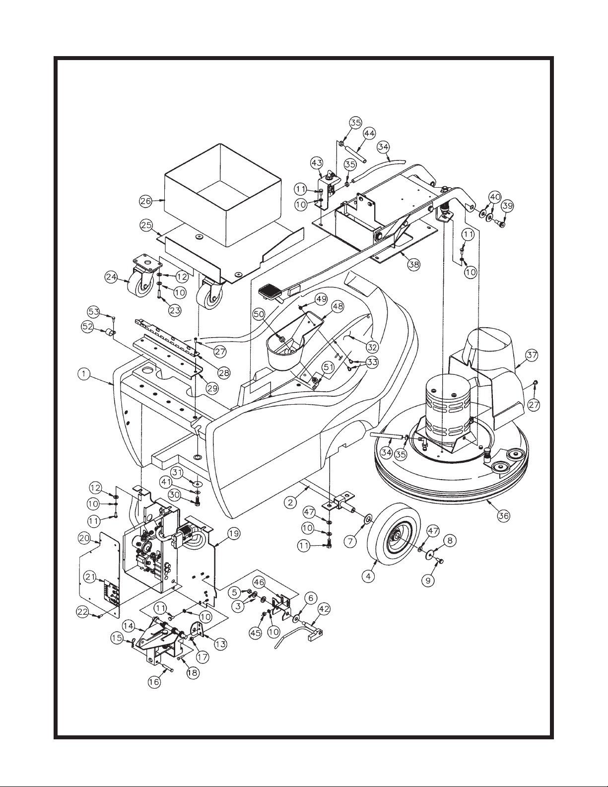
BASE ASSEMBLY
7
Page 11

BASE ASSEMBLY
Parts List
Item Part No. Qty. Description
1 200102 1 Base
2 200250 1 Axle Weldment
3 712301 2 WSR-Flat .38 x .88 x .06
4 762332 2 Wheel, 8 x 2 w/Bearing
5 711375 1 Nut-Nyloc 3/8-16
6 711578 2 WSR-Flat ½ Brass
7 712318 2 WSR-Flat ¾ x 1.12 x .12
8 712759 2 WSR-Flat 5/16 x 1.37 x .06 SS
9 712042 2 Bolt-WSR HH 5/16-18 x .62
10 711544 22 WSR-Helical ¼
11 711203 19 BLT-HH ¼-20 x .62
12 711505 15 WSR-Flat ¼
13 200158 1 Pin Bracket
14 200153 1 Squeegee Mechanism Assy.
15 711808 1 Cotter Pin
16 210415 1 Clevis Pin 5/16
17 260183 3 Nut ¼ NPT Nyloc
18 712564 1 Bolt-HH ¼-20 x 1 SS
19 200265 1 Back Panel Assy., BD
20 200314 1 Electrical Box Cover
21 711125 4 SCR-ST-B #10 x ½
22 710180 10 SCR-MC ¼-20 x ¾
23 200345 2 Caster, 3 ½”
24 200125 1 Battery Tray Weldment
25 210048 1 Battery Liner
26 712565 5 SCR-MC ¼-20 x .62 SS
27 200145 1 Hinge
28 200146 1 Hinge Plate
29 711228 4 Bolt-HH 5/16-18 x ¾
30 711507 4 WSR-Flat .37 x 1.12 x .06
31 200233 1 Bottom Cover
32 712822 3 SCR-THMS 10-24 x ½
33 200235 1 Hose Nylobraid 17.50
34 450076 2 Crimp Clamp 185R SS
35 200315 1 Scrubhead Assy. 115V
36 200328 1 Scrubhead Assy. 240V
36A 200186 1 Motor Cover
37 200280 1 Motor Lift Assy.
38 712099PLT 2 Shoulder Bolt ½ x .50
39 711510 4 WSR-Flat .50 x 1.38 x .10
40 711545 4 WSR-Helical 5/16
41 200130 1 Pawl Weldment
42 200260 1 Solution Valve Assy. - BD
43 200234 1 Solution Hose 51.00
44 711316 3 Nut-Hex ¼-20
45 200129 1 Pawl Mounting Bracket
46 711575 2 WSR-Flat .312 x .75 x .06
8
Page 12

TANK ASSEMBLY
9
Page 13

TANK ASSEMBLY
Parts List
Item Part No. Qty. Description
1 200101 1 Solution/Recovery Tank
2 200147 3 Bracket, Vac Motor
3 200173 1 Float, Housing
4 210122 1 Drain Hose Wirelock
5 200232 1 Cable, Tank
6 200251 1 Stand Pipe Assembly
7 200258 1 Muffler Assembly
8 200270 1 Hose, ¾ Solution Drain
9 200023 1 Garden Hose Cap
10 210409 1 Fitting, Brass 3/8 MPT
11 210410 1 Fitting, Brass 3/8 FPT
12 210414 1 “O” Ring 2-113
13 250039 3 Clamp, Plastic 5/16 3305
14 260203 1 Hose Clamp 102120 Murray
15 290017 1 Gasket, Molded, Vac Motor
16 3321335 1 Clamp-Hose 3” NOM
17 383321 1 Elbow ¾ MPT ¾ Barb PP
18 200022 1 ¾” MGHT x Hose Barb
19 829129 2 Clamp, Crimp ¾ Barb
20 430050 1 Filter Screen 4 x 4
21 260155 1 Foam Float
22 430090 1 Float Valve Weldment
23 460019 2 Gasket
24 710207 1 SCR-MC 6-32 x .87 ST PL
25 200234 Ref. Solution Hose
26 130118 1 Solution Strainer
27 712540 3 SCR-MC #10-24 x .375 SS
28 712574 1 CR Bolt SS ¼-20 x 3”
29 712667 2 Nut-Hex ¼-20 SS Nyloc
30 200231 1 Gasket, Shutoff
31 712568 1 SCR-MC ¼-20 x 2.25 SS
32 832996 1 Terminal Block 2-Pole VDE
33 833316 1 Drain Plug
34 740232 1 Vac Motor 115V
34A 741030 1 Vac Motor 240V
35 760245 2 Hose Clamp 62P24
36 760343 1 Tube Hose 24/32B
37 762384 2 Bushing .277 x .375 x .37 SS
38 830062 1 Fitting Brass 90 3/8 MPT
39 710180 3 SCR-MC ¼-20 x .75
40 711544 6 Lockwasher - Helical ¼
41 711505 6 Washer ¼
42 715285 1 Decal, 200X
43 200024 1 Black Vinyl Washer
44 712759 4 WSR-Flat .31 x 1.37 x .06 SS
45 310008 1 O-Ring
46 712565 3 SCR-MC 1/4-20 x .625 SS
47 805613 1 Hose Cuff, Grey Vinyl
10
Page 14

UPPER ASSEMBLY
Parts List
Item Part No. Qty. Description
1 200160 1 Tank Assembly
2 200178 2 Gasket, Lid
3 200136 1 Gasket, Solution Lid
4 200103 1 Tank Lid
5 712120 2 Shoulder Bolt ½ x 2
6 710178 6 SCR-MC ¼-20 x ½
7 711503 2 WSR-Flat #10
8 711125 5 SCR-ST-B #10 x ½
9 760286 1 Wire Formed Hook
10 200176 1 Dump Hose Bracket
11 200170 1 Console Assy. - Brush Drive
12 715284 1 Decal, Solution Control
13 383367 1 Spring Clip
14 430053 1 Solution Control Cable
15 711228 6 Bolt-HH 5/16-18 x ¾
16 711545 6 WSR-Helical 5/16
17 711575 6 WSR-Flat 5/16
18 200032 1 Console Back Cover Weldment
19 450054 1 Vacuum Recovery Hose
11
Page 15

CONSOLE ASSEMBLY
Parts List for 200330
Item Part No. Qty. Description
1 200104 1 Console
2 200134 1 Console Bracket Right
3 200135 1 Console Bracket Left
4 200151 1 Hinge Bracket Weldment
5 200322SP 1 Dashboard ASM BD
6 712320 4 WSR-Nylon .22 x .45 x .04
7 712540 8 SCR-MC #10-24 x .37 SS
8 711575 6 WSR-Flat .31 x .75 x.06
9 711545 6 WSR-Helical 5/16
10 711228 6 Bolt-HH 5/16-18 x .75
11 711505 2 WSR-Flat ¼
12 200240 1 Squeegee Lift Assy.
13 711544 6 WSR-Helical ¼
14 711203 6 Bolt-HH ¼-20 x .62
15 740812 3 Switch (optional 4th)
16 740811 3 Switch Boot (optional 4th)
17 833827 1 O-Ring 1.25 ID x .187
18 250038 1 Retainer Bag Clip
19 830292 1 Cord Assy. 75 ft. 115V
19A 743287 1 Cord Assy. 25 Meters 240V
20 430103 1 Snap Body
21 760142 1 Clamp Ring
22 450012 1 Strain Relief
23 711161 1 SCR Hi-Lo 10 x .75
12
Page 16

MOTOR LIFT ASSEMBLY
Parts List
Item Part No. Qty. Description
1 200120 1 Base Plate Weldment
2 260036 2 Pin
3 712310 4 WSR-Flat .52 x .88 x .06
4 711527 6 WSR-Flat 5/8 x 1.12 x .12
5 762340 2 Oilite Bushing ½
6 260041 4 Oilite Flanged Bushing ½
7 200115 1 Lift Arm Weldment
8 711713 2 E-Ring ½
9 710207 2 SCR-MC 6-32 x .87
10 740128 1 Microswitch
11 711430 1 Tinnerman Clip
12 833638 2 Brass Stud
13 711368 2 Wing Nut
14 740132 2 Insulator Glastic
15 711546 2 WSR-Helical 3/8
16 711241 2 Bolt-HH 3/8-16 x ¾
17 711376 1 Nut-Nyloc ½-13
18 260137 1 Compression Spring
19 200110 1 Spring Bracket
20 200149 1 Adjustment Rod
21 200116 1 Pedal Arm Weldment
22 762294MCH 1 Pedal
23 711202 2 Bolt-HH ¼-20 x ½
24 711544 2 WSR-Helical ¾
25 450040 2 Elbow 3/8 Barb x 3/8 MPT
26 809413MCH 1 Solution Valve Machined
27 829463 1 WSR-Flat SS
28 828975 1 WSR-Neoprene .75 x 1.5 x .09
29 200259 1 Valve Bracket
13
Page 17

SCRUBHEAD ASSEMBLY
Parts List
Item Part No. Qty. Description
1 200109 1 Motor Platform Weldment - BD
2 200187 1 Brush Shroud Weldment
3 200194 1 Pin, Brush Release
4 200294 2 Shroud Strap
5 210066 1 Retainer Bolt
6 200293 1 Shroud Skirt
7 260183 1 Nut ¼ NPT Nylon
8 320268 1 Key, ¼ x 5/16 x 1.00
9 430035 1 Drive Hub
10 500033 1 Locking Screw
11 710986 4 SCR-SC 3/8-16 x 1.00
12 711202 3 SCR-MC ¼-20 x ½
13 711544 3 WSR-Helical ¼
14 711615 1 Roll Pin 1/8 x ¾
15 712318 1 WSR-Flat ¾
16 740428 1 Gear Motor 115V
16A 740432 1 Gear Motor 240V
17 833102 1 Spring
18 833325 1 Hose Barb 90° Nylon
19 711578 2 WSR-Flat ½ Brass
20 712310 8 WSR-Flat .52 x .87 x .06
21 430085 2 Bumper Wheel
22 712759 2 WSR-Flat .31 x 1.37 x .06 SS
23 710975 2 SCR-SC 5/16-18 x .87
24 712560 8 SCR-MC ¼-20 x .50 Nyloc
25 200029 1 Pitch Adj. Bar Weldment
26 711334 1 Nut-Hex ½-13
27 710754 1 Bolt-HH ½-13 x 2 ¾
28 711505 1 WSR-Flat ¼
29 711373 1 Nut-Nyloc ¼-20
30 743425 1 Ground Wire
14
Page 18

BACK PANEL
Parts List
Item Part No. Qty. Description
1 742307 2 Switch, McGill, VDE
2 200229 1 Bracket, Kill Switch
3 710307 4 SCR-MC 6-32 x 1
4 200326 1 Cover Switch Box
5 711125 10 SCR-ST #10 x .5
6 711316 2 Nut-Hex ¼-20
7 711544 2 WSR-Helical ¼
8 711430 2 Nut-Tinnerman 6-32
9 200332 1 Wire Guard Cover
10 200311 1 Back Panel Weldment
11 742748 1 Boot, Circuit Breaker
12 740220 1 Circuit Breaker, 20A
13 830540 1 Flg. Male Receptacle 115V
13A 832682 1 230V Receptacle
14 200317 1 230V Receptacle Bracket
15 742256 1 RFI Filter 230V Only
16 712818 2 SCR-MC 10-24 x .5
17 741300 1 Terminal Block
18 740202 1 Receptacle Bridge 230 Only
19 712813 5 SCR-MC 10-24 x .75
20 712908 2 Nut-Flange Wizz 10-24
21 712635 2 Nut-Hex 10-24 SS
22 711543 2 WSR-Helical #10
15
Page 19

BACK PANELDASHBOARD
Parts List for 200265
1 200124 1 Backpanel Weldment
2 742749 2 Circuit Breaker Plug
3 711368 2 Wing Nut, ¼-20
Item Part No. Qty. Description
4 740132 2 Insulator (Glastic)
5 742748 2 Boot, Circuit Breaker
6 740247 1 Circuit Breaker 30
7 742000 2 Diode Assembly
8 740549 1 Circuit Breaker 50
9 711210 2 SCR-HH ¼-20 x 1 ¼
11 743260 1 Wire Harness, 200X BD
10 740159 1 CB175 Red Housing Only
12 788147 2 Solenoid 24VDC
13 833638 2 Brass Stud
14 711425 6 Whiz-Nut ¼-20
16
Parts List for 200299
1 200179 1 Dashboard Plate
2 715283 1 Decal 200 Dashboard
3 740216 1 Battery Gauge
Item Part No. Qty. Description
4 740711 3 Switch Dreefs
5 742202 1 Disconnect Switch 125A
6 740811 3 Switch Boot
Page 20

Item Part No. Qty. Description
16 260273 1 Front Blade Strap
17 260322 1 Squeegee Blade 260 Quarry
18 320191 1 Squeegee Mounting Bracket
19 711578 2 WSR-Flat ½ Brass
Parts List for 200219
1 711668 2 Clevis Pin 3/8 x 1
2 711507 7 WSR-Flat .37 x 1.12 x .06
3 711808 2 Cotter Pin - Hair #13
Item Part No. Qty. Description
4 210153 2 Roller Wheel
20 260287 2 Wing Bolt ½-13 x 1.00
21 320156 1 Mounting Bracket - Right
22 200169 1 Pitch Control Weldment
23 320157 1 Mounting Bracket - Left
24 712301 1 WSR-Flat .37 x .87 x .07
25 711379 1 Nut- Flanged Wizz 5/16-18
26 711374 1 Nut-Nyloc 5/16-18
27 712562 4 Bolt-HH ¼-20 x .75 SS
5 762281 2 Bushing .37 x .500 x .25
6 200222 1 Squeegee Casting, 200
7 260203 1 Rear Squeegee Blade
8 260264 1 Reinforcement Blade
9 260272 1 Rear Blade Strap
11 712668 8 Wing Nut ¼-20 SS
10 711504 12 WSR-Flat .25 x .56 SS
12 712571 2 Bolt-SS Carr ¼-20 x 1.50
13 712572 2 Bolt-SS Carr ¼-20 x 2.00
28 712758 4 WSR-Helical ¼ SS
29 712081 2 Bolt-Shoulder 3/8 x .75
14 712573 2 Bolt-SS Carr ¼-20 x 2.50
15712574 2Bolt-SS Carr ¼-20 x 3.00
17
Page 21

WIRING DIAGRAM, 115V
18
Page 22

WIRING DIAGRAM, 240V CE
19
Page 23

LIMITED WARRANTY
Minuteman International, Inc. warrants to the original purchaser/user that this product is free from defects in workmanship and
materials under normal use and service for a period of three years from date of purchase. In addition, Minuteman International,
Inc. will, at its option, honor labor warranty claims for the first 12 months from date of sale, provided such claims are submitted
through and approved by factory authorized repair stations. Minuteman International, Inc. will, at its option, repair or replace
without charge, except for transportation costs, parts that fail under normal use and service when operated and maintained in
accordance with the applicable operation and instruction manuals.
This warranty does not apply to normal wear, or to items whose life is dependent on their use and care, such as belts, cords,
switches, hoses, rubber parts, electrical motor components or adjustments. Parts not manufactured by Minuteman International,
Inc. such as engines, batteries, battery chargers, hydraulic pumps, and tires are covered by and subject to the warranties and/
or guarantees of their manufacturers. Please contact Minuteman International, Inc. for procedures in warranty claims against
these manufacturers.
Special warning to purchaser — Use of replacement filters and/or prefilters not manufactured by Minuteman International,
Inc. or its designated licensees, will void all warranties expressed or implied.
A potential health hazard exists without exact original equipment replacement.
All warranteed items become the sole property of Minuteman International, Inc. or its original manufacturer, whichever the case
may be.
Minuteman International, Inc. disclaims any implied warranty, including the warranty of merchantability and the warranty of
fitness for a particular purpose. Minuteman International, Inc. assumes no responsibility for any special, incidental or consequential
damages.
This limited warranty is applicable only in the U.S.A. and Canada, and is extended only to the original user/purchaser of this
product. Customers outside the U.S.A. and Canada should contact their local distributor for export warranty policies. Minuteman
International, Inc. is not responsible for costs or repairs performed by persons other than those specifically authorized by
Minuteman International, Inc. This warranty does not apply to damage from transportation, alterations by unauthorized persons,
misuse or abuse of the equipment, use of non-compatible chemicals, or damage to property, or loss of income due to malfunctions
of the product.
If a difficulty develops with this machine, you should contact the dealer from whom it was purchased.
This warranty gives you specific legal rights, and you may have other rights which vary from state to state. Some states do not
allow the exclusion or limitation of special, incidental or consequential damages, or limitations on how long an implied warranty
lasts, so the above exclusions and limitations may not apply to you.
World Headquarters Minuteman Canada, Inc.
Minuteman International, Inc. 2210 Drew Road
111 South Rohlwing Road Mississauga, Ontario
Addison, Illinois 60101 L5S 1B1
(630) 627-6900 (905) 673-3222 986765
FAX (630) 627-1130 FAX (905) 673-5161 Printed in U.S.A.
 Loading...