

Page 1

Electronic Service
Manuals
This electronic document is provided as a service to our customers.
We do not create the contents of the information contained in this document. Should you have detailed questions pertaining to the information
contained in this document, you may contact Michco, or the manufacturer which provided the original information in this electronic deliverable. Michco’s only part in this electronic deliverable was the electronic
assembly process. By providing this manual on line we are not guaranteeing parts availability.
You may contact Michco through the following methods:
Phone (517) 484-9312 or (800) 331-3339
2011 N. High St. -- Lansing, Michigan -- 48906
Fax: (517) 484-9836
Email: CustServe@Michco.com
Web site: www.Michco.Com
Parts Web site: www.FloorMachineParts.Com
Order Parts on Line at:
www.FloorMachineParts.Com
Directly to Parts & Service:
By Email: Shop@Michco.com
By Fax: (517) 702-2041
By Voice: Use numbers above.
Serving the Cleaning Industry Since 1922
Notice: All copyrighted material remains property of original owners, all trademarks are property of respective owners.
Manuals are subject to Manufacturer’s reproduction limitations. Originals or reproductions were provided by manufacturers
through a request. We make no warranty as to the correctness of information provided in this document and you assume
all risk. By placing these manuals on line we are not declaring our corporation to be an manufacturer authorized dealer or
provider, please check our web site for authorized manufacturers we represent.
Page 2
200X
Model: MC20001QP, CE
Traction Drive
Deluxe
Floor Scrubber
Battery
OPERATION
SERVICE PARTS
MC20002QP, CE
CARE
Page 3
Page 4

TABLE OF CONTENTS
Page
Safety Instructions 1
Electrical Requirements 2
Control Panel Identification 3
Operating Instructions 4
Squeegee Adjustments 5
Brush Installation/Removal 6
Base Assembly - Traction Drive 7, 8
Base Assembly - Deluxe 9, 10
T ank Assembly 11, 12
Upper Assembly 13
Console Assembly 14
Motor Lift Assembly - Deluxe 15, 16
Motor Lift Assembly - T raction Drive 17
Scrubhead Assembly 18
Dashboard & Back Panel Assembly 19
Squeegee Lift & Mechanism Assembly 20
Squeegee Assembly Complete 21
Wiring Diagram 22, 23
Wiring Diagram - CE 24, 25
Page 5

IMPORT ANT SAFETY INSTRUCTIONS
CAUTION
Operators must read and understand this manual before operating or maintaining this equipment.
• Keep hands and feet clear of moving parts while machine is in operation.
• All switches must be in the “OFF” position when charging batteries.
• Electrical motors and components can cause an explosion when operated near explosive materials
or vapors. Do not operate this machine near flammable materials such as solvents, thinners, fuels,
grain dusts, etc.
• Make sure all switches are turned “OFF” and battery connections are removed before performing
any maintenance procedures.
• S tore or park this machine on a level surface only .
• These machines are designed for level floor operation only. DO NOT OPERATE on ramps or
inclines.
• Battery acid can cause burns. When working on or around batteries, wear protective clothing and
safety glasses. Remove metal jewelry . Do not lay tools or met al objects on top of batteries.
• This machine is not suitable for picking up hazardous dust.
Charging batteries generates explosive gases. DO NOT CHARGE BATTERIES WHEN OPEN
FLAMES OR SPARKS ARE PRESENT. DO NOT SMOKE. Make sure the charger is turned off
before disconnecting it from the batteries. Charge the batteries in a well-ventilated area.
Maintenance and repairs must be performed by authorized personnel.
SA VE THESE INSTRUCTIONS
1
Page 6

ELECTRICAL REQUIREMENTS:
This piece of equipment operates on 24 V olt DC.
BATTERY REQUIREMENTS:
2 x 12V 185 Amp Hour 20 Hour Rate Deepcycle P/N 956709
2 x 12V 210 Amp Hour 20 Hour Rate Deepcycle P/N 956210
BATTERY SERVICE AND INSTALLATION:
Warning: Battery acid can cause burns. When working on or around batteries, wear protective clothing
and safety glasses. Remove metal jewelry . Do not lay tools or metal objects on top of batteries.
BATTERY INSTALLATION:
1. Raise tank assembly by gripping the front of the tank and lift the tank backward as shown in Fig. 1.
2. Install batteries as shown in Figure 2.
CHARGING OF BATTERIES:
Charging of batteries generates explosive gases. DO NOT CHARGE BA TTERIES WHEN OPEN
FLAMES OR SPARKS ARE PRESENT. DO NOT SMOKE. Make sure the charger is turned off
before disconnecting it from the batteries. Charge the batteries in a well-ventilated area. Fluid levels
should be checked before and after charging and maintained at the proper levels.
2
Page 7
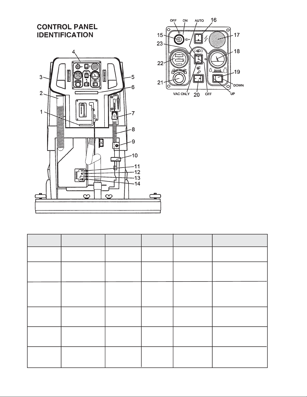
1. Squeegee lift lever
2. Recovery dump hose
3. Reverse handle
4. Dashboard control panel
5. Forward handle
6. Safety bar switch
7. Solution control lever
8. Solution dump hose
9. Quick disconnect - Aux. out (Deluxe only)
10. Foot pedal (TD only)
11. Circuit breaker - Brush
12. Circuit breaker - Vac
13. Circuit breaker - System
14. Circuit breaker - Transaxle
15. Keyswitch
16. Main power
17. Emergency button
18. Brush pressure gauge
19. Brush control
20. Pump switch
21. Speed control
22. Battery condition meter
AUTO SCRUBBER BRUSH DESCRIPTION
TYPE DESCRIPTION DURABILITY* COLOR TO PADS U SE
Bassine Natural Fiber Short Dark Brown Red Light duty
Nylon Nylon Medium Black Tan/Red General cleaning
Dyna-Scrub Nylon impregnated Long Light Red General scrubbing,
with 500 Grit vinyl tile, ceramic
Silicon Carbide tile, epoxy floors,
Fine Bristle, urethane finish,
Power-Scrub Nylon impregnated Long Rust Red/Blue Moderate aggressive
Poly-Grit Nylon impregnated Long Green Brown/Black Aggressive stripping
Strata-Grit Nylon impregnated Long Dark Blue Black Heavy duty
Dense Fill
with 120 Grit Silicon scrubbing, tile floors,
Carbide Fine Bristle, concrete floors
Dense Fill
with 80 Grit and scrubbing, tile
Silicon Carbide floors, unfinished
Coarse Bristle concrete floors
with 46 Grit stripping/scrubbing
Silicon Carbide
Coarse Bristle
••
•
Durability is dependent on floor surface, chemicals used and proper care.
••
COMPARISON RECOMMENDED
general cleaning,
acid etching
& scrubbing vinyl
floors, ceramic tile
& concrete floors
uneven concrete floors
unfinished concrete
3
Page 8

OPERATING INSTRUCTIONS
BEFORE STATING, FAMILIARIZE YOURSELF WITHTHE MACHINE AND ITS CONTROLS
(SEE “MACHINE OVERVIEW” & CONTROL PANEL DIAGRAMS)
1. Filling: Fill the solution tank with the desired amount of water and add liquid cleaning solution to
the proper dilution ratio. DO NOT USE powdered cleaning chemicals. Powders are unlikely to
dissolve thoroughly , resulting in clogging the in-line solution filter. This can reduce or stop water
flow to the brush.
2. Close lid.
3. Turn on machine by lifting the red emergency disconnect button (17) so it is in the up position.
Turn keyswitch (15) clockwise to “on” position and turn on main power switch (16).
4. Adjust main speed control (21) to full counter-clockwise position.
5. Lower brush assembly.
- T o lower the brush, first push the pedal (10) slightly outward on the machine (unlock it), and
then release it slowly or by pressing “brush down” switch (19) on Deluxe models.
- T o lift the brush, press the pedal (10) down until lift mechanism engages or by pressing ”brush
up” switch (19) on Deluxe models.
- Brush will come on automatically when brush in on the floor and “forward” (5) or “reverse” (3)
handles are squeezed and remain on approximately 5 seconds after release.
6. Adjust solution control feed lever.
7. Select vacuum operations:
- “V acuum On” mode (23), V acuum will remain on until switched to the “off” position
- “V acuum Auto” mode (23), V acuum will come on automatically when “forward” or “reverse”
handle is squeezed, and scrubhead is on the floor . The brush and vacuum will remain on
approximately 5 minutes.
8. Lower squeegee assembly by lowering handle (1).
9. Squeeze “forward” handle (5) and adjust forward speed (21) as desired.
After Use:
1. Turn off solution feed.
2. Raise squeegee assembly .
3. Turn off vacuum motor .
Solution and recovery tanks should be emptied after every use.
MAINTENANCE:
Daily 1. Clean float assembly & squeegee blades. Vac filter
2. Recharge batteries (check battery acid levels before and after charging).
Monthly 1. Check wear on squeegee blades.
2. Grease front wheels.
3. Grease pivot points on brush motor assembly .
Every 500 hours check condition of carbon brushes on vacuum motor and brush drive motor.
4
Page 9

SQUEEGEE ADJUSTMENTS
The squeegee set up is pre adjusted at the factory. Adjustments may be required to get optimum
performance for different floors and conditions.
1 Ensure that the scrubber is on a relatively flat surface. T urn on the main power switch and turn the key
switch clockwise to the on position. Raise the scrubhead off the floor. Turn the vacuum switch to the
“vacuum only” position.
2 Turn the speed control knob counter clockwise to the low speed position. Lower the squeegee (item 1)
to the floorand squeeze the forward control handle, moving the machine one or two feet forward to
check the rear squeegee blade (item 8) for uniform deflection to the floor.
3 If uneven deflection or lay is evident, minor adjustments may be necessary to avoid streaking and
uneven wear on the blade.
4 To correct this, loosen the wing jam nut (item 4) in order to adjust the castor height. If the squeegee
blade is deflecting too much, the castors need to be lowered to control the down pressure. Lower the
castor by turning the exposed threaded stem (item 9) on the castor clockwise. Make the adjustment a
few turns at a time. Repeat Step 2.
5 If the blades are not deflecting enough, raise the castor by turning the stem counter clockwise to adjust
the castor height to allow more down pressure on the squeegee. Repeat Step 2.
6 Make sure that there is an even deflection on the entire length of the rear blade. Adjust the castors and
retighten the wing jam nuts to lock the castor setting in place.
7 Pitch adjustment is necessary if the outer ends on the squeegee blade does not contact the floor and
there is too much deflection in the middle area or if the outer ends are over deflected and there is no
contact in the middle.
8 To adjust the pitch, lower the squeegee to the floor. Loosen the lock nut (item 3) in the turnbuckle
assembly. Turning the turnbuckle (item 2) clockwise or counter clockwise controls the forward and
backward pitch of the squeegee. Having the rear blades deflected uniformly along the entire length is
the desired set up.
9 Repeat Step 2 until the desired set up is achieved.
10 In certain applications where a non-slotted front wiper blade (item 6) is needed, detach the squeegee
assembly by loosening the wing bolts (item 7). Unlock the clamp on the front squeegee to release the
straps and flip the blade over to the non-slotted side. Reattach straps and lock the clamp back in place.
11 You can also easily replace the rear blade by unlatching the latch (item 5) and removing the straps by
sliding them off the assembly.
5
Page 10
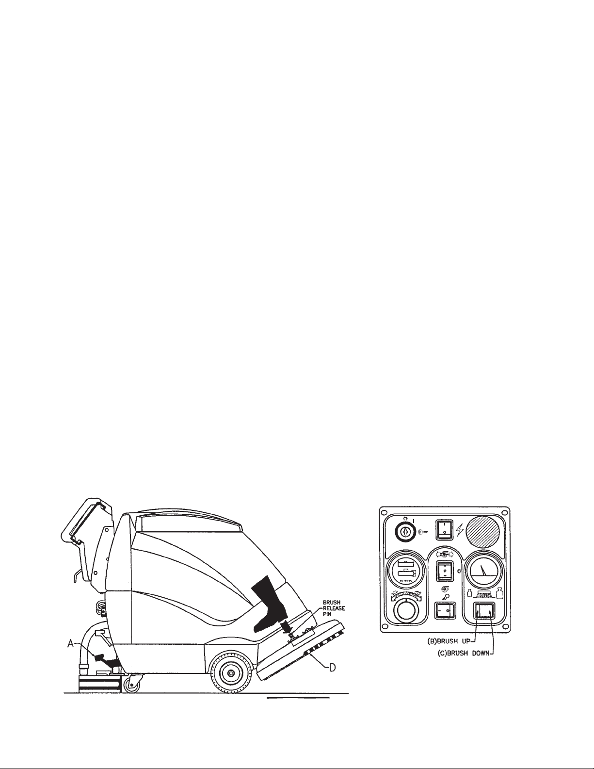
BRUSH INSTALLATION - REMOVAL
INSTALLATION
Traction Drive
1. Raise the scrubhead to the “UP” position by depressing the pedal (A) downward as shown on
Fig. 1.
Deluxe Model
1. Raise the scrubhead to the “UP” position by pressing the switch “BRUSH UP” (B) switch as
shown on Fig. 2 until the scrubhead stops retracting upwards.
2. Center brush (D) under the scrubhead shroud while lining up the center hex drive hub and pressing
the brush up until the brush engages on the drive hub.
REMOVAL
Traction Drive
1. Raise the scrubhead to the “UP” position by depressing the pedal (A) downward as shown on
Fig. 1.
Deluxe Model
1. Raise the scrubhead to the “UP” position by pressing the switch “BRUSH UP” (B) switch as
shown on Fig. 2 until the scrubhead stops retracting upwards.
2. Remove the brush (D) by stepping on the “BRUSH RELEASE PIN” on the top of the scrubhead
shroud as shown on Fig. 1 below .
Figure 1 Figure 2
6
Page 11

BASE ASSEMBLY - TRACTION DRIVE
7
Page 12

TRACTION DRIVE Parts List
8
Page 13

BASE ASSEMBLY - DELUXE
9
Page 14

DELUXE Parts List
10
Page 15

T ANK ASSEMBLY
11
Page 16

T ANK ASSEMBLY Part List
12
Page 17

UPPER ASSEMBLY
Parts List
13
Page 18

CONSOLE ASSEMBL Y
Parts List
14
Page 19

MOTOR LIFT - DELUXE
15
Page 20

Parts List
Item Part No. Qty. Description
1 200249 1 Base Plate Weldment - Deluxe
2 260036 2 Pin
3 712310 4 WSR-Flat .52 x .88 x .06
4 711527 6 WSR-Flat 5/8 x 1.12 x .12
5 762340 2 Oilite Bushing 1/2
6 260041 4 Oilite Flanged Bushing 1/2
7 200242 1 Lift Arm Weldment - Deluxe
8 711713 2 E-Ring 1/2
9 710312 2 SCR-MC 6-32 X 1.75 ZINC
10 740128 2 Microswitch
11 711430 1 Tinnerman Clip
12 833638 2 Brass Stud
13 711368 2 Wing Nut
14 740132 2 Insulator Glastic
15 743032 1 Terminal Block
16 712822 2 SCR-THMS 10-24 x 1/2
17 711807 1 Cotter Hair Pin
18 711672 1 Clevis Pin 1/2
19 711376 1 Nut-Nyloc 1/2-13
20 828264 2 Cup Washer
21 260137 1 Compression Spring
22 200110 1 Spring Bracket
23 711334 1 Nut-Hex 1/2-13
24 200149 1 Adjustment Rod
25 712126 1 Shoulder Bolt 5/16 x 1.75
26 711515 6 WSR-Flat .406 x .81 x .063
27 711373 1 Nut-Nyloc 1/4-20
200290 Motor Lift Assembly
200285 Pump/Actuator Assembly
28 200174 1 Pump Mounting Bracket
29 712638 4 Nut-Nyloc 10-24 SS
30 200248 1 Pivot Tube
31 831965 1 Clevis Pin 3/8 x 1.63
32 711808 1 Cotter Pin
33 743503 1 Actuator
34 833299 1 Pump
35 711505 4 WSR-Flat 1/4
36 712532 4 SCR-MC 10-24 x 1 SS
37 833325 2 Elbow 3/8 Barb x 1/4 NPT
38 450076 2 Crimp Clamp 185R
39 200282 1 Hose Pump Inlet
40 200281 1 Hose Pump Outlet
41 710329 2 SCR-MC 8-32 x .5 C.E. Only
42 742391 1 RFI Filter, Corcom C.E. Only
43 200335 1 RFI Bracket C.E. Only
44 711372 2 Nut-Nyloc 8-32 C.E. Only
200139 Valve Assembly - Deluxe
45 342430 2 Fitting 3/8 Barb x 3/8 MPT
46 743505 1 Water Solenoid 24V
47 829463 1 WSR-Flat SS
48 828975 1 WSR-Neoprene .75 x 1.5 x .09
49 830062 1 3/8 Street 90
50 383332 1 3/8 Closed Nipple
51 809413MCH 1 Solution Valve Machined
52 200259 1 Valve Bracket
53 210408 1 Fitting Brass Tee 3/8 NPT
54 450040 1 Elbow 3/8 Barb x 3/8 MPT
q Brass
16
Page 21

Parts List
MOTOR LIFT TRACTION DRIVE
17
Page 22

SCRUBHEAD ASSEMBL Y
Parts List
18
Page 23

Parts List
ITEM PART NO. REQ’D DESCRIPTION
1 200124 1 BACK PANEL WELDMENT
2 711210 2 BLT-HH 1/4-20 X1.25 STL ZINC
3 711368 2 NUT-WING NYLOC 114-20 PL
4 711425 8 NUT-FLANGEDWIZZI/4-20
5 712320 1 WSR.22X.45X.O4NYL
6 712536 2 SCR-MC 10-24 X .62 SS
7 712823 1 SCR-THUMB 10-24 Xl ZINC
8 740132 2 INSULATOR (GLASTIC)
9 740159 1 CIRCUIT BRKR-175 RED HOUSING
10 740238 2 CIRCUIT BRKR-18AMP PUSH BUTTON
11 740247 1 CIRCUIT BRKR-3OAMP PUSH BUTTON
12 740549 1 CIRCUIT BRKR-5OAMP PUSH BUTTON
13 742091 1 TIMER-DELAY ON BREAK 24VDC
14 742000 3 DIODE ASY 24/26/32/38/AC
15 742403 1 SHUNT, CALIBRATED
16 742748 4 CIRCUIT BRKR-BOOT
17 743250 1 ELECTRICAL ASSY 200XD
18 788147 3 SOLENOID-24VDC
19 833638 2 BRASS STUD
DASHBOARD BACK P ANEL
Parts List
19
Page 24

SQUEEGEE LIFT SQUEEGEE MECHANISM
Parts List Parts List
20
Page 25

Parts List
21
Page 26

WIRING DIAGRAMS
22
Page 27

200X TRACTION DRIVE AND DELUXE
23
Page 28

200X TRACTION DRIVE AND DELUXE
24
Page 29

CE 200X TRACTION DRIVE AND DELUXE
25
Page 30

CE 200X TRACTION DRIVE AND DELUXE
26
Page 31

LIMITED WARRANTY
Minuteman International, Inc. warrants to the original purchaser/user that this product is free from defects in workmanship and
materials under normal use and service for a period of three years from date of purchase. In addition, Minuteman International,
Inc. will, at its option, honor labor warranty claims for the first 12 months from date of sale, provided such claims are submitted
through and approved by factory authorized repair stations. Minuteman International, Inc. will, at its option, repair or replace
without charge, except for transportation costs, parts that fail under normal use and service when operated and maintained in
accordance with the applicable operation and instruction manuals.
This warranty does not apply to normal wear, or to items whose life is dependent on their use and care, such as belts, cords,
switches, hoses, rubber parts, electrical motor components or adjustments. Parts not manufactured by Minuteman International,
Inc. such as engines, batteries, battery chargers, hydraulic pumps, and tires are covered by and subject to the warranties and/
or guarantees of their manufacturers. Please contact Minuteman International, Inc. for procedures in warranty claims against
these manufacturers.
Special warning to purchaser — Use of replacement filters and/or prefilters not manufactured by Minuteman International,
Inc. or its designated licensees, will void all warranties expressed or implied.
A potential health hazard exists without exact original equipment replacement.
All warranteed items become the sole property of Minuteman International, Inc. or its original manufacturer, whichever the case
may be.
Minuteman International, Inc. disclaims any implied warranty, including the warranty of merchantability and the warranty of
fitness for a particular purpose. Minuteman International, Inc. assumes no responsibility for any special, incidental or
consequential damages.
This limited warranty is applicable only in the U.S.A. and Canada, and is extended only to the original user/purchaser of this
product. Customers outside the U.S.A. and Canada should contact their local distributor for export warranty policies. Minuteman
International, Inc. is not responsible for costs or repairs performed by persons other than those specifically authorized by
Minuteman International, Inc. This warranty does not apply to damage from transportation, alterations by unauthorized persons,
misuse or abuse of the equipment, use of non-compatible chemicals, or damage to property, or loss of income due to
malfunctions of the product.
If a difficulty develops with this machine, you should contact the dealer from whom it was purchased.
This warranty gives you specific legal rights, and you may have other rights which vary from state to state. Some states do not
allow the exclusion or limitation of special, incidental or consequential damages, or limitations on how long an implied
warranty lasts, so the above exclusions and limitations may not apply to you.
Minuteman International, Inc.
111 South Rohlwing Road
Addison, Illinois 60101
Phone 630-627-6900
Fax 630-627-1 130
www.minutemanintl.com
986764
Rev . A 01/07
Printed in U.S.A.
 Loading...