

Page 1
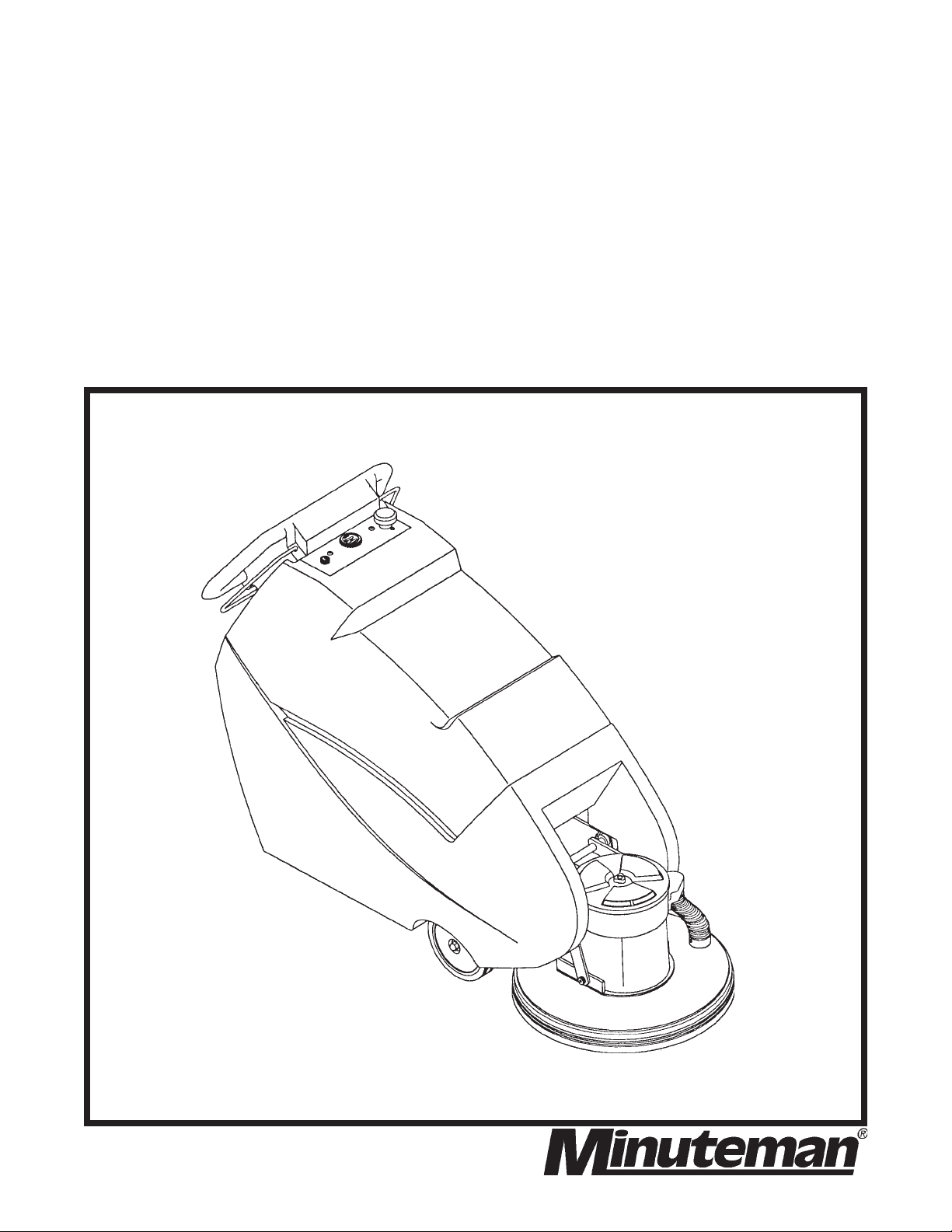
Battery
Model:
Burnisher
OPERATION
M27000-00
M27000-00 CE
SERVICE PARTS
CARE
Revised 7/02
Page 2

Page 3

CONTENTS
ILLUSTRATION, SPARE PARTS, OPERATION & SERVICE
PRECAUTIONS ............................................................................................................... 1
OPERATION & INSPECTION ........................................................................................... 2
PAD INSTALLATION & ADJUSTMENTS ....................................................................... 3-8
BATTERIES ..................................................................................................................... 9
MACHINE OVERVIEW, CONTROL PANEL DIAGRAM .................................................. 10
MAIN FRAME ASSEMBLY........................................................................................ 11-12
DRIVE UNIT ASSEMBLY .......................................................................................... 13-14
HANDLE ASSEMBLY ............................................................................................... 15-16
ELECTRICAL ASSEMBLY ........................................................................................ 17-20
WARRANTY POLICY ....................................................................................... Back Cover
Page 4

IMPORTANT SAFETY INSTRUCTIONS
CAUTION:
Operators must read and understand this manual before operating or maintaining
this machine.
Keep hands and feet clear of moving parts while machine is in operation.
Disconnect the power to the machine by pressing the red Emergency Disconnect Button when
charging batteries or during installation or removal of pads.
During operation, loose objects on the floor can become dangerous projectiles if struck by the high
speed pad. Special attention should be paid in removing or avoiding loose floor tile, electrical
cables, telephone connection boxes.
Electrical motors and components can cause an explosion when operated near explosive materials
or vapors. Do not operate this machine near flammable materials such as solvents, thinners, fuels,
grain dust, etc.
Keep machine moving to reduce the risk of damaging floor finish and floor.
Make sure the red Emergency Disconnect Button is pressed and the battery connector is unplugged
from the machine before performing any maintenance procedures.
Store or park this machine on a level surface only.
These machines are designed for level floor operation only. Do not operate on ramps or inclines.
Battery acid can cause burns. When working on or around batteries, wear protective clothing and
safety glasses. Remove metal jewelry. Do not lay tools or metal objects on top of batteries.
Charging batteries generates explosive gases. DO NOT CHARGE BATTERIES WHEN OPEN
FLAMES OR SPARKS ARE PRESENT. DO NOT SMOKE. Make sure the charger is turned off
before disconnecting it from the machine. Charge the batteries in a well-ventilated area with the
battery cover removed completely.
Maintenance and repairs must be performed by authorized personnel.
SAVE THESE INSTRUCTIONS
1
Page 5

OPERATING INSTRUCTIONS
INSPECTION:
Carefully unpack and inspect your burnisher for shipping damage. Each unit is tested and thoroughly
inspected before shipment; any damage is the responsibility of the delivery carrier who should be
notified immediately.
ELECTRICAL:
This machine is battery operated and designed to operate on 36 volts DC (3) 12 volt batteries.
BATTERIES:
Burnishers are shipped with batteries.
3 required - Part No. 956210 12V 210 AH 20 Hr. Rate
We do not recommend mixing AMP hour capacities. Any alternate battery sets can be used if
they equal physical size and capacity. See page 9 for service and installation.
OPERATION:
Before starting, familiarize yourself with the machine and its controls (see “Machine Overview” and
“Control Panel” diagrams). To turn the machine ON, do the following:
1. Make sure the cover is on the machine so the safety interlock switch is in the closed
position.
2. Make sure that no battery charger is plugged into the recharge port (there is also a safety
interlock switch in this location).
3. Lift the red emergency disconnect button so it is in the up position.
4. Turn the keyswitch clockwise.
2
Page 6

Once the initial functions listed above have been performed, press the “I” button on the control panel
to turn the machine on. This will illuminate the “ON” light found on the control panel and activate the
battery condition meter.
Before operating the machine, check the condition of the batteries. The battery condition meter can
be read by looking at which light is illuminated on the meter. The green light on the right end of the
meter indicates that the batteries are fully charged. As the batteries discharge, the light moves to the
left. When the light under “1/2” is illuminated, the batteries are 1/2 charged. Once the meter shows
approximately 1/4 charge, there is not enough power left in the batteries to start the burnishing motor
and the batteries need to be recharged.
The machine can be used in either an “Automatic” mode or a “Manual” mode. In the “Automatic”
mode, the burnishing head is automatically raised or lowered to compensate for irregularities in the
floor. This produces an even finish. In the “Manual” mode, the height of the burnishing head is set by
the operator. The head stays at this height until it is adjusted again by the operator. In either mode,
the motion of the machine is controlled by the handles that are located on either side of the console.
By squeezing the right handle against the console, the machine will move forward. By squeezing the
left handle against the console, the machine will move backwards. The speed of the machine is
controlled by the knob located on the control panel. The speed (in both directions) is increased by
turning the knob clockwise.
The vertical array of five lights in the middle of the control panel under “Pad Pressure” gives an
indication of pad pressure. The top light under the word “MIN” is illuminated when the pad is minimally
touching the floor. The light directly above the word “MAX” is illuminated to give indication of the
maximum amount of pad pressure. The remaining three lights designate varying levels of pad
pressure between “MIN” and “MAX”. It is normal in “AUTOMATIC” mode for the lights to periodically
“bounce” up and down on the display. This “bouncing” is a result of the machine encountering high
and low areas in the floor. As a high spot is encountered, the lights will move down the array. If a low
spot is encountered, the lights will move up the array. It is also normal for the motor to sound like it is
slowing down over a high spot. If the motor did not slow down, there is a possibility that the floor
finish could be damaged.
There are (2) circuit breakers at the bottom left rear corner of the machine. The top one (70A) is for
the burnishing motor. The bottom one (18A) is for the traction drive. If the machine is not operating
properly, check to see if the circuit breakers have popped. If so, depress the top of them to reset.
3
Page 7

AUTOMATIC MODE:
To operate the burnishing motor in the “Automatic” mode, select one of the buttons located on the
right side of the control panel under the word “Automatic”. The top button is for “light pad pressure”.
The middle button is for “medium pad pressure”, and the bottom button is for “heavy pad pressure”.
Caution should be used when operating the machine in the “heavy pad pressure” setting. If the
machine is moved too slowly, there is a possibility that the floor finish will be damaged due to
excessive pad pressure.
Once an automatic setting has been chosen, a light adjacent to that button will illuminate. A light
under the word “Automatic” will also illuminate. The burnishing head will move to the “Start” position,
which is approximately 2 inches above the floor. When the head is in this position, the burnishing
motor will turn on when either of the direction handles is grasped and the machine begins to move.
The pad will lower to engage the floor. The level of pad pressure is automatically maintained at the
selected pressure setting. If the light under “Automatic” is flashing, the burnishing head is being
adjusted to ensure the correct pad pressure is being maintained. When the light stops flashing, the
head is no longer being adjusted up or down. If, while the machine is being used, a high spot or a low
spot in the floor is encountered, the light will begin flashing and the height of the burnishing head will
be adjusted to maintain the correct pad pressure. If the light does not stop flashing and the burnishing
head is constantly being raised and lowered, the controller is having difficulty calibrating the machine
to the floor conditions. Simply turn the speed down to a slower rate until the light stops flashing.
When burnishing is complete, raise the head using the “UP” arrow under “MANUAL” on the control
panel until it is in the full up position. The head will move slowly until it passes the “Start” position. At
that point it will raise more rapidly.
MANUAL MODE:
To operate the burnishing motor in the Manual mode, press one of the arrow buttons
on the control panel under the word “MANUAL” to control pad pressure. When the “UP” arrow is
pressed, the burnishing head is raised. When the “DOWN” arrow is pressed, the head is lowered.
When the Manual mode is selected, the light under the word “MANUAL” will illuminate. The pad will
not spin unless the burnishing head is below the “Start” position. Pad pressure is indicated by the
pad pressure indicator lights described above.
It is not advisable to operate the machine with the “MAX” light illuminated for an extended period of
time as 1) damage to the floor finish could occur, and 2) the burnishing motor may stop spinning due
to a circuit breaker trip.
4
Page 8

(Note: In the event the burnishing motor does stop spinning the operator should check the circuit
breaker at the lower left rear corner of the machine to restart the motor)
When burnishing is complete, raise the head using the “UP” arrow until it is in the full up position. The
head will move slowly until it passes the “Start” position. At that point it will raise more rapidly.
SENSITIVITY ADJUSTMENTS:
During use of the 2700 burnisher in the “Automatic” mode, the on-board controller constantly monitors
the pad pressure on the floor. The first time the burnishing head is lowered, the light on the control
panel under the word “Automatic” will blink. This alerts the operator that the machine is attempting to
calibrate itself to the current floor condition. When the machine determines that the pad pressure
level is adjusted properly, the light will quit blinking. This initial time frame when the light is blinking is
called “First Time to Calibrate”.
When/If the current floor condition changes the light on the control panel under the word “Automatic”
will again begin to blink to alert the operator that the machine is once again attempting to calibrate
itself to the current floor condition.
There is a time delay which occurs between the machine sensing the change in the floor condition
and actually making a change to its calibration settings. This time frame is called “Time to Recalibrate”.
The light on the control panel under the word “Automatic” will not begin to blink during this time delay.
If the “Time To Recalibrate” setting has been exceeded and the floor has not resumed its original
condition then the machine will automatically begin to recalibrate itself.
When the current floor condition changes the light on the control panel under the word “Automatic”
begins to blink to alert the operator that the machine is once again attempting to calibrate itself to the
current floor condition. The machine will again automatically raise and lower the head until the proper
calibration is found. When the new position is found, the light on the control panel under the word
“Automatic” will quit blinking and the head will quit moving. The time frame when the light is again
blinking and the burnishing head is moving is called “Second Time to Calibrate”.
As the machine is used over varying floor conditions, it will continually go through the “Time to
Recalibrate” and “Second Time to Calibrate” cycle. Again, these are the operations that the machine
performed:
1) “First Time to Calibrate” - The initial time frame when the machine is raising and
lowering the burnishing head to find the correct position for proper pad pressure.
2) “Time to Recalibrate” - The time frame between when the machine senses a change
in floor conditions and when it reacts to that change.
3) “Second Time to Calibrate” - All time frames after the initial one when the burnishing
head is being raised or lowered to compensate for changing floor conditions.
5
Page 9

The sensitivity of these three features can be changed to meet the needs of the floor that is being
burnished. They can be made more sensitive, making the machine raise and lower the head more
often to ensure that proper pad pressure is being maintained even over small changes in floor
conditions. These features can also be made less sensitive, making the machine react less to
changes in floor conditions. Making the machine less sensitive can be helpful if the location that is
being burnished has particularly wavy floors and the machine can not keep up with the changing floor
conditions. Care should be taken when changing the sensitivity. When the machine is too sensitive
or not sensitive enough, there is a possibility that the floor finish can be damaged.
To change the sensitivity of the machine, the programming mode must be entered. To do this, press
and hold the “OFF” button. Then press and hold the “UP” and “DOWN” buttons simultaneously. Then
release the “OFF” button. Then release the “UP” and “DOWN” buttons. The machine is now in the
programming mode. Notice that the “ON” light is now dimly blinking.
To change the “First Time to Calibrate” setting, after entering the programming mode, press and
hold the “ON” button. Then press and hold the “DOWN” button. Release the “ON” button, then release
the “DOWN” button. A combination of lights will illuminate in the pad pressure array. By pressing the
“UP” or “DOWN” buttons, the lights will move accordingly. The closer the array is to the word “MIN”,
the quicker the machine will calibrate itself. The closer the array is to the word “MAX”, the longer it will
take for the machine to calibrate itself. During this time, the machine is finding an average floor
height, therefore if the machine calibrates itself too quickly, it might not have a true representation of
the floor. If the machine calibrates itself to slowly, it may never lock-in to an average. Once the correct
sensitivity adjustment has been made, press the “OFF” button to exit the programming mode and
save the setting.
To change the “Time to Recalibrate” setting, after entering the programming mode, press and hold
the “ON” button. Then simultaneously press and hold the “Heavy Pad Pressure” and “Light Pad
Pressure” buttons. Release the “ON” button and then simultaneously release the other two buttons.
A combination of lights will illuminate in the pad pressure array. By pressing the “UP” or “DOWN”
buttons, the lights will move accordingly. The closer the lights are to the word “MIN” the quicker the
machine will start to recalibrate itself after it encounters a high or low spot in the floor. The closer the
lights are to the word “MAX”, the longer it will take for the machine to start to recalibrate itself after it
encounters a high or low spot in the floor. Once the correct adjustment has been made, press the
“OFF” button to exit the programming mode and save the setting.
6
Page 10

To change the “Second Time to Calibrate” setting, after entering the programming mode, press and
hold the “ON” button. Then press and hold the “Heavy Pad Pressure” button. Release the “ON”
button, then release the “Heavy Pad Pressure” button. A combination of lights will illuminate in the
pad pressure array. By pressing “UP” or “DOWN”, the lights will move accordingly. The closer the
array is to the word “MIN”, the quicker the machine will recalibrate itself after the initial calibration
level has been found. The closer the array is to the word “MAX”, the longer it will take for the machine
to recalibrate itself. This functions just like the “first time to calibrate” described above. Once correct
adjustment has been made, press “Off” button to exit the programming mode and save the setting.
To reset the machine back to its factory sensitivity settings, after entering the programming mode,
press and hold the “Heavy Pad Pressure”, “Medium Pad Pressure”, and “Light Pad Pressure” buttons.
Then release the “ON” button and then simultaneously release the other three buttons. Most of the
lights on the control panel will blink at random. To reset to the factory settings, press the “UP” button
and then press the “OFF” button to exit the programming mode.
Power to the control board must be disconnected to disable the programming mode. This can be
most easily done by pressing the red emergency stop button. All values will be stored in the memory.
CAUTION: Machine will not be used on surfaces with a gradient exceeding 2%.
The machine shall be used only instructed and authorized persons. When cleaning, servicing or
maintaining the machine, replacing parts or converting to another function the power source shall be
switched off. Operated machines shall be disconnected by removing the power plug and batteryoperated machines shall be disconnected by removing the key of the power switch or any other
effective means.
Before use, all covers and doors shall be put in the position specified in the instructions for use.
For machines with traction drive and a mass exceeding 100 kg:
· In order to prevent unauthorized use of the machine the power source shall be switched off or
locked, for example, by removing the key of the power switch.
· Machines left unattended shall be secured against unintentional movement.
· During operation attention shall be paid to other persons, especially children.
7
Page 11

AFTER USE:
Turn machine off by pressing the “O” button on the control panel. Machine can be cleaned with a mild
detergent and a damp cloth. Batteries should be charged after each use or when the battery condition
meter shows a low charge. To recharge the batteries, plug the 36V charger into the recharge port
located at the bottom right rear corner of the machine. The recharge port has an interlock switch so
the machine can not be turned on when the batteries are being recharged. Once the meter on the
battery charger reads 0 amps, the batteries are recharged. This should take approximately 6 hours
if the batteries are completely discharged.
PAD INSTALLATION:
Using the “UP” arrow under “MANUAL”, raise the burnishing head to the full up position. Press the
“O” button on the control panel to turn the machine off. Remove the center cup locking device by
gripping on outer edges and turning clockwise. NOTE: center cup cannot be pulled out, it must be
unscrewed. After removing used pad, place new pad on pad driver assembly using outer flange to
center pad. Push center locking cup through pad and into pad driver assembly. The ratchet teeth on
the center cup will engage into the pad driver assembly and should be pushed in as far as possible.
If further tightening is needed, rotate the center locking cup counterclockwise.
8
Page 12

BATTERY SERVICE AND INSTALLATION:
WARNING
Battery acid can cause burns. When working on or around batteries, wear protective clothing and
safety glasses. Remove metal jewelry. Do not lay tools or metal objects on top of batteries.
CHARGING OF BATTERIES:
Charging batteries generates explosive gasses. DO NOT
CHARGE BATTERIES WHEN OPEN FLAMES OR SPARKS ARE
PRESENT. DO NOT SMOKE. Make sure the charger is turned
off before disconnecting it from the batteries. Charge the batteries
in a well-ventilated area. Fluid levels should be checked before
and after charging and maintained at the proper levels. If the
burnisher is not used for extended periods of time, batteries should
be kept fully charged with a boost charge once a week.
CARBON BRUSH REPLACEMENT:
Design life of carbon brushes is between 1800-2000 hours. Replace brushes if worn to 3/8" or less,
broken, or chipped. All carbon brushes should be replaced when motor is serviced. 4 required, P/
N 572003. Red indicator on control panel will glow when carbon brush service is required.
Battery Cable Wiring
CARBON BRUSH SERVICE:
1. Disconnect batteries from machine.
2. Remove cover, filter, and collection tray from dust control assembly.
3. Remove two screws that hold dust control housing and motor cover to motor.
4. Push motor cover up and out of the way of the top of the motor.
5. Blow out top of motor with air line.
6. Loosen screw and remove carbon brush lead.
7. Slide brush spring off the back of carbon brush and remove brush.
8. Reverse order for installation.
9
Page 13

101112
Page 14

Page 15

Parts Listing
ITEM NO. PART NO. QTY. DESCRIPTION
1 670035 1 Frame Weldment
2 711373 2 1/4-20 Nyloc Nut
3 710178 3 SCR-MC 1/4-20 x .50
4 740147 1 Charge Connector
5 740128 1 Switch
6 711430 1 Tinnerman Plate
7 710207 2 6-32 x .87 Screw
8 711210 2 1/4-20 x 1.25 HH Bolt
9 742202 1 Disconnect Switch
10 710180 4 SCR-MC 1/4-20 x .75
11 742310 1 Hour Meter
12 670032 1 Release Rod Weldment
13 833102 1 Spring, Compression
14 710197 6 SCR-MC 5/16-18 x .75 PHI
15 670036 1 Handle Guide Weldment
16 260041 1 Bushing
17 712822 2 Screw-THMS 10-24 x .500
18 711543 2 WSR-Helical #10
19 670010 1 Handle
20 670060 1 Wire Handle - Left
21 670098 1 Handle Brace
22 829052 4 Nylon Flanged Bushing
23 807385 1 Knob
24 711381 1 Nut-Hex 1/2-13
25 670033 1 Wire Handle - Right
26 711721 8 Retaining Ring
27 670017 2 Handle Rail
28 741005 1 Key Switch
29 260272 2 Nut-Nylon 1/4 NPT
30 670013 1 Battery Box
31 320271 1 90° Nozzle Body
32 450076 1 Crimp Clamp SS 185R
33 260224 1 Hose, Clear 18”
34 320273 1 Hose, Shut-Off Clamp
35 670119 1 Pivot Weldment
36 712310 2 WSR-Flat .52 x .87 x .06 STPL
37 711524 2 WSR-Wave .52 x .87 x .01
38 712122 2 SLD BLT 1/2 x 5/8
39 710961 4 SCR-SC 1/4-20 x .37 ST NI
40 260595 1 Dust Skirt
41 711512 6 WSR-Flat .75 x 1.37 x .08
42 760401 1 Center Cup
43 711516 1 WSR-Flat .31 x 1.25 x .05
44 710856 1 SCR-SC 5/16 - 24 x .62
45 711545 1 WSR-Helical 5/16
ITEM NO. PART NO. QTY. DESCRIPTION
46 713003 3 BLT-HH 1/4-20 x 1 #5
47 670075 1 Multi-Flex Pad Driver
48 762397 4 Leveler Bolt
49 670101 4 Spacer
50 809857 4 Conical Spring
51 711564 3 WSR-External Lock 1/4
52 670047 1 Motor Plate Weldment
53 260559 1 Pad Shroud Assembly
54 742461 1 Motor 36V 2.5 HP
55 150209 1 Foam Tape
56 572003 4 Carbon Brush Replacement
57 670014 1 Motor Cover
58 711202 1 Bolt-HH 1/4-20 x .50
59 711505 1 WSR-Flat 1/4
60 670094 1 Dust Hose
61 762402 1 Hose Cuff
62 711351 2 Nut-Acorn 10-32
63 762131PTD 1 Hose Fitting
62 762411 1 Gasket-Dust Collection Tray
65 762396B 1 Filter Housing
66 710556 2 SCR-MC 10-32 x .75
67 762416PLT 1 Threaded Spacer
68 762404 1 Filter Gasket
69 762132 1 Dust Collection Tray
70 762403 1 Filter Pad
71 390061 1 O-Ring
72 715252 1 Decal-PAMS
73 762415 1 Filter Housing Cover
74 711524 1 WSR-Wave .52 x .87 x. 01
75 833214 1 Knob, 1/4-20
76 711594 1 WSR-Flat .56 x .88 x .03
77 762409PLT 1 Threaded Pin Retainer
78 480049 1 Gasket
79 711144 2 SCR-ST-F 10-24 x .50
80 762410 1 Bushing .196 x .312 x .265
81 711903 1 Rivet, Pop .19 x .25
82 711241 4 BLT-HH 3/8-16 x .75
83 711546 4 WSR-Helical 3/8
84 840049 2 Stamped STL Pillow Block
85 881059 2 Bearing .75 ID W/L Collar
86 711554 4 Internal Lock Washer
87 710182 1 SCR MC 1/4-20 x 1.00
88 670117 2 Flanged Bushing
89 230030 1 Band Clamp
90 260598 6 Anti-Skid, Burnisher Skirt
Page 16

13
Page 17

Parts Listing
ITEM NO. PART NO. QTY. DESCRIPTION
1 670035 1 Frame Weldment
2 670039 1 Linkage Arm Weldment
3 711615 1 Rollpin .12 x .75
4 711509 6 WSR-Flat .52 x 1.06 x .09
5 670051 1 Parking Brake Weldment
6 260041 2 Bushing
7 833374 1 Cotter Pin
8 711668 1 Clevis Pin 3/8 x 1
9 320210 1 Brake Cable Assembly
10 711241 4 Bolt-HH 3/8-16 x .75
11 711546 4 WSR-Helical 3/8
12 320140 1 Yoke Weldment
13 742459 1 Actuator
14 742460 1 Transaxle
15 670031 2 Transaxle Mount
16 380-532-20 2 Cotter Key
17 827110 1 Caster
18 712109 2 Clevis Pin ½ x 1.75
19 210141 2 Wheel 8”
20 361233 2 Key 3/16 Sq. x 1.50
21 711228 4 BLT-HH 5/16-18 X .75
22 711545 4 WSR-Helical 5/16
23 711575 4 WSR-Flat .31 x .75 x .06
24 740128 1 Switch
25 711430 2 Tinnerman Plate
26 711203 8 BLT-HH ¼-20 x .62
27 711373 2 ¼-20 Nyloc Nut
28 740147 1 Charge Connector
29 361135 1 Charge Plug Bracket
30 710207 4 SCR-MC 6-32 x .87 STPL
31 711210 2 BLT-HH ¼-20 x 1.25
32 833329 1 Switch
33 711368 2 Wing Nut ¼-20
34 833638 2 Brass Stud
35 740132 2 Insulator-Glastic
36 711544 8 WSR-Helical ¼
37 711202 2 BLT-HH ¼-20 x .50
38 712318 8 WSR-Flat .75 x 1.12 x .12
39 670070 2 Acorn Nut ½-20
40 670011 1 Lower Body
41 670009 1 Cover
42 715251 2 Decal
43 715385 1 Decal, Minuteman
44 670055 1 Actuator Pin Sleeve
45 670054 1 Actuator Pin
46 711713 1 Retaining Ring-E Ext. .50
47 670069 2 Actuator Pin Spacer
48 712099PLT 2 BLT-Shoulder ½ x ½
49 760594 2 Extension Spring
50 670092 1 Heyco Bushing 1½”
51 711524 2 WSR-Wave .52 x .87 x .01
52 809148 2 E-Ring .75
14
Page 18

15
Page 19

Parts Listing
ITEM NO. PART NO. QTY. DESCRIPTION
1 670035 1 Frame Weldment
2 715249 1 Decal-Instructions
3 670033 1 Wire Handle - Right
4 670060 1 Wire Handle - Left
5 670010 1 Handle Console
6 742476 1 Fuse 10A
7 742498 1 Control Board Assembly
8 809874 1 Knob
9 742471 1 Potentiometer Assembly
10 712822 4 SCR-THMS 10-24 x .500
11 710207 8 SCR 6-32 x .87
12 670044 1 Switch Bracket
13 711430 4 Tinnerman Clip
14 833329 2 Micro Switch
15 670062 2 Cam Assembly
16 711004 2 Set Screw 1/4-20 x .25
17 320198 1 Brake Bracket Weldment
18 740128 1 Snap Switch
19 760592 1 Knob
20 760594 1 Extension Spring
21 320210 1 Cable, Brake Assembly
22 711668 1 Clevis Pin 3/8 x 1.0
23 833374 1 Cotter Pin 7/64 x 1.0
24 712081 1 Shoulder Bolt 5/16
25 320205 1 Parking Brake Lever
26 833102 1 Compression Spring
27 670068 1 Electrical Panel
28 740243 2 Solenoid 36V 200A
29 710178 12 SCR-MC ¼-20 x .50
30 711372 2 Nut-Nyloc 8-32
31 740803 1 Speed Control 36V
32 805637 1 Insulator
33 740132 2 Insulator- Glastic
34 833638 2 Brass Stud
35 711368 2 Wing Nut ¼-20
36 742403 2 Calibrated Shunt
37 200340 2 Spacer
38 712536 2 SCR-MC 10-24 x .62
39 740131 1 Circuit Breaker 70A
40 740238 1 Circuit Breaker 18A
41 715246 1 Decal, 36V
42 670012 1 Bottom Shroud
43 711109 8 SCR-ST-B 12 x .50 STPL
44 760263 1 Foam Tape
45 260180 1 “U” Channel
46 715250 1 Decal, Circuit Breakers
47 670056 1 Access Panel
48 715255 1 Decal, Parking Brake
49 712569 1 SCR-MC ¼-20 x 1.50
50 742472 1 Switch
51 670089 1 Switch Bracket
52 670088 1 Switch Lever
53 670093 1 Compression Spring
16
Page 20

171819
Page 21

Page 22

Page 23

20
Page 24

LIMITED WARRANTY
Minuteman International, Inc. warrants to the original purchaser/user that this product is free from defects in workmanship and
materials under normal use and service for a period of three years from date of purchase. In addition, Minuteman International,
Inc. will, at its option, honor labor warranty claims for the first 12 months from date of sale, provided such claims are submitted
through and approved by factory authorized repair stations. Minuteman International, Inc. will, at its option, repair or replace
without charge, except for transportation costs, parts that fail under normal use and service when operated and maintained in
accordance with the applicable operation and instruction manuals.
This warranty does not apply to normal wear, or to items whose life is dependent on their use and care, such as belts, cords,
switches, hoses, rubber parts, electrical motor components or adjustments. Parts not manufactured by Minuteman International,
Inc. such as engines, batteries, battery chargers, hydraulic pumps, and tires are covered by and subject to the warranties and/
or guarantees of their manufacturers. Please contact Minuteman International, Inc. for procedures in warranty claims against
these manufacturers.
Special warning to purchaser — Use of replacement filters and/or prefilters not manufactured by Minuteman International, Inc.
or its designated licensees, will void all warranties expressed or implied.
A potential health hazard exists without exact original equipment replacement.
All warranteed items become the sole property of Minuteman International, Inc. or its original manufacturer, whichever the case
may be.
Minuteman International, Inc. disclaims any implied warranty, including the warranty of merchantability and the warranty of
fitness for a particular purpose. Minuteman International, Inc. assumes no responsibility for any special, incidental or consequential
damages.
This limited warranty is applicable only in the U.S.A. and Canada, and is extended only to the original user/purchaser of this
product. Customers outside the U.S.A. and Canada should contact their local distributor for export warranty policies. Minuteman
International, Inc. is not responsible for costs or repairs performed by persons other than those specifically authorized by Minuteman
International, Inc. This warranty does not apply to damage from transportation, alterations by unauthorized persons, misuse or
abuse of the equipment, use of non-compatible chemicals, or damage to property, or loss of income due to malfunctions of the
product.
If a difficulty develops with this machine, you should contact the dealer from whom it was purchased.
This warranty gives you specific legal rights, and you may have other rights which vary from state to state. Some states do not
allow the exclusion or limitation of special, incidental or consequential damages, or limitations on how long an implied warranty
lasts, so the above exclusions and limitations may not apply to you.
World Headquarters Minuteman Canada, Inc.
Minuteman International, Inc. 2210 Drew Road
111 South Rohlwing Road Mississauga, Ontario
Addison, Illinois 60101 L5S 1B1
(630) 627-6900 (905) 673-3222
FAX (630) 627-1130 FAX (905) 673-5161
986742
Printed in U.S.A.
 Loading...